1954 F-100 (D)
#31
 06-25-2012, 08:51 PM


New User
Join Date: May 2007
Location: Stafford, VA
Posts: 15
Likes: 0
Received 0 Likes
on
0 Posts
 Looking good !
#32
06-26-2012, 07:55 PM
Wheels on Ground
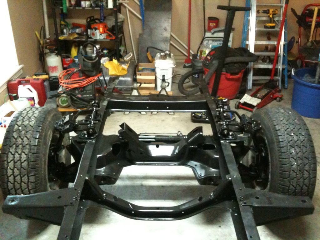
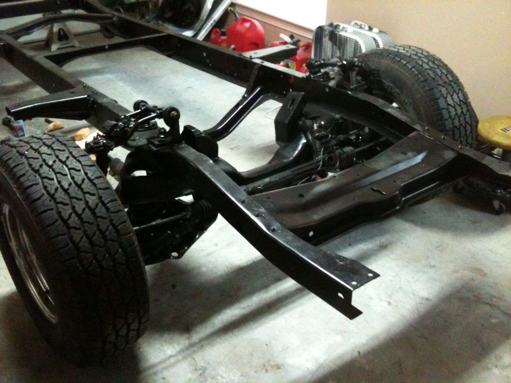
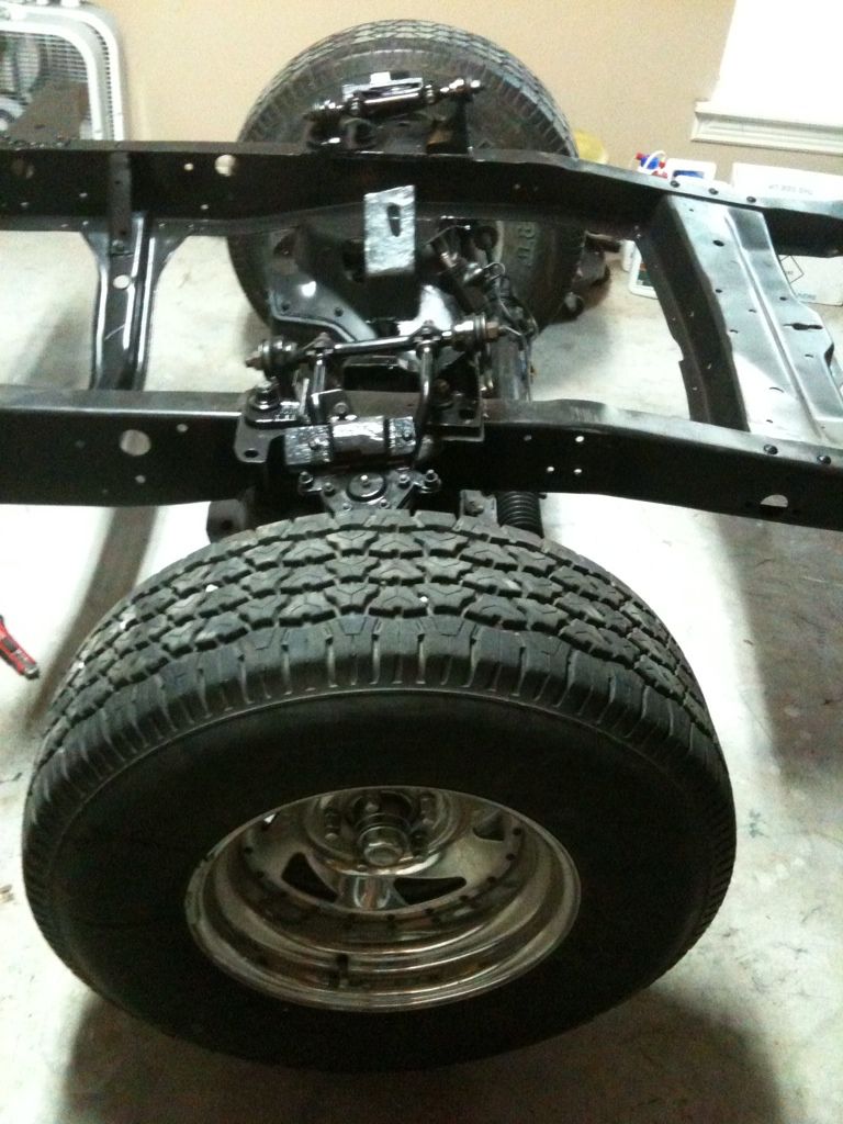
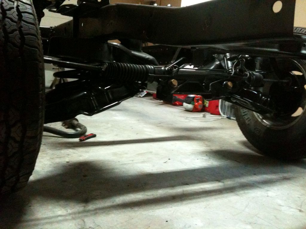
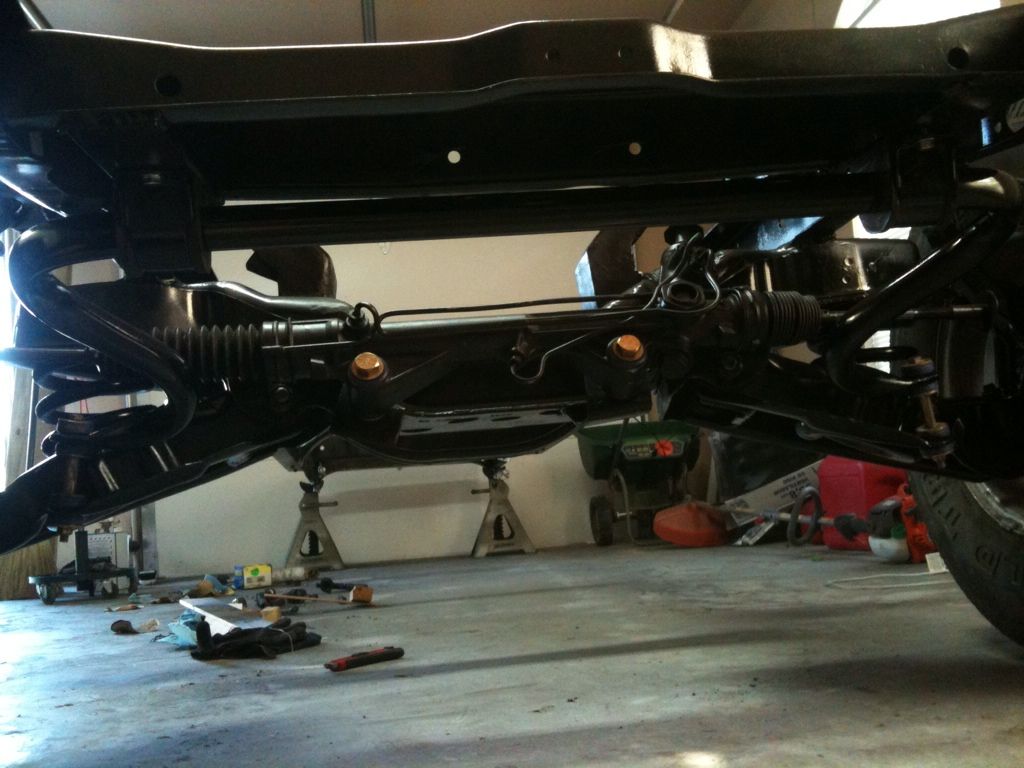
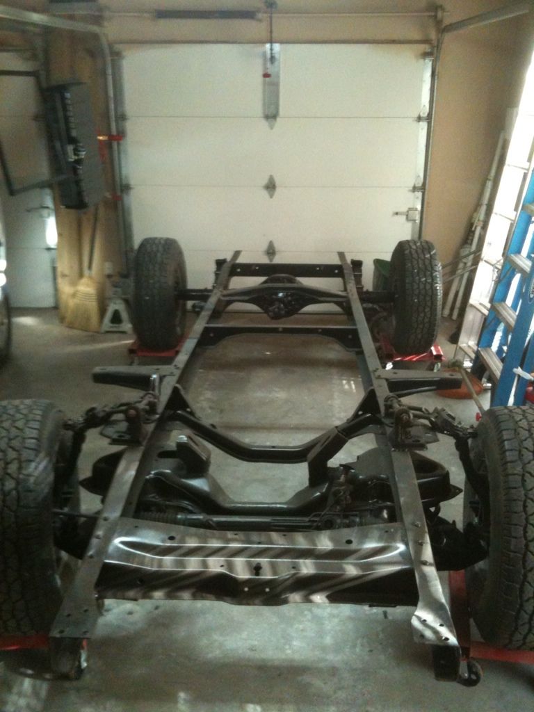
This evening I installed the passenger side spindle, rotor and decided to put both side wheels on so I can put them on the ground. I will get the calipers later. These are not the final wheels but what I have in 5X4.5. I want stock looking wheels. I also installed but not tightened the rack and pinion. Tomorrow I think I will put the sway bar on or at least get started.
#33
06-26-2012, 07:59 PM
New User
Join Date: May 2007
Location: Stafford, VA
Posts: 15
Likes: 0
Received 0 Likes
on
0 Posts
#34
06-26-2012, 08:35 PM
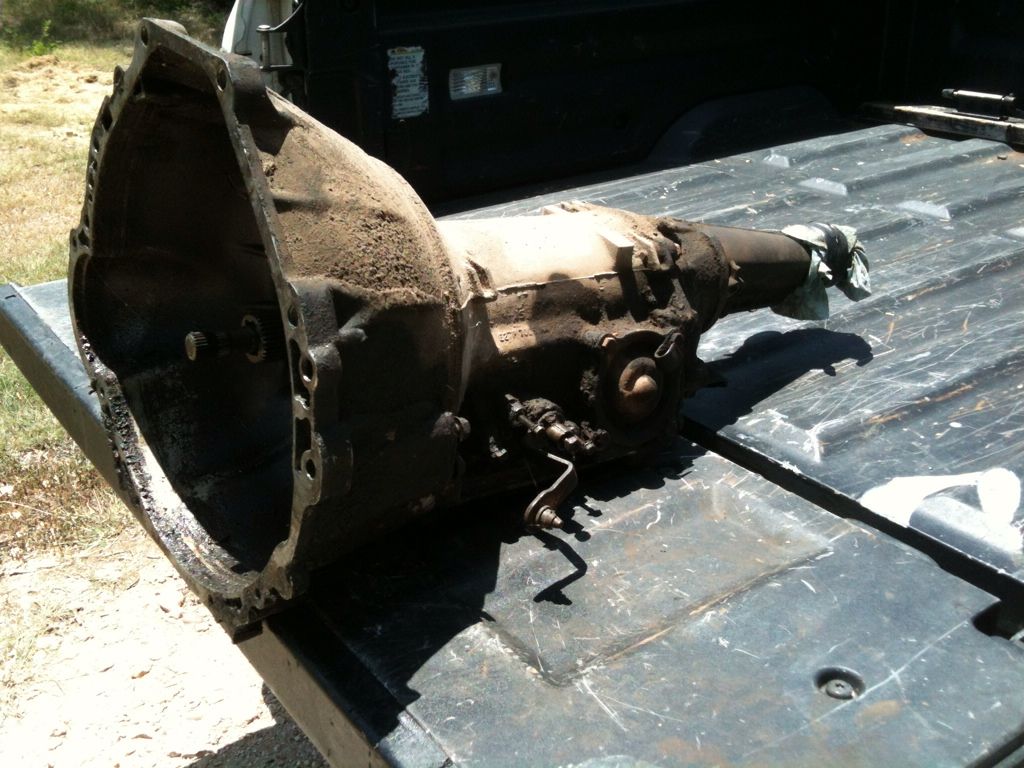
I have a 351W and C4. As soon as I finish rebuilding the rear end and have all 4 on the ground I plan to rebuild the trans then the engine. There are pictures of it in my motor mockup post early in the thread. Its real dirty so I will put some degreaser and my power washer to work. Can't wait; every day I feel like I am closer to cranking her over.
#35
06-26-2012, 08:40 PM
New User
Join Date: May 2007
Location: Stafford, VA
Posts: 15
Likes: 0
Received 0 Likes
on
0 Posts
I have a 302 out of a 1968 Mercury with a C4 that I will also be rebuilding and installing. My issues right now are as soon as I box the frame and install the Mustang II front end, I then have to figure out the measurements for the engine and Trans mounting points. Having never done that, I am a little apprehensive about where and how to start it. Any suggestions you would be willing to pass on as to where to start?
#36
06-27-2012, 08:39 AM
Randall,
The main concern is interference. I knew that the first step was putting everything (I mean everying, e.g. cab, rack and pinion, steering column, trans, radiator, rear end) in place to see exact placement. It is best to have your engine fully assembled. Honestly, I had to redo my motor mounts three times for heights issues. I also had a problem with the engine sitting unparallel to the frame in one mockup. In my situation having my mockup in my shop (without electricity) and my welder in my house garage I had to mockup, teardown and transport (100 yrds.) three times. What a pain. Others have probably done this part easier but like you this was my first with placement of the engine. In your case since lots of people are doing the Mii IFS you should have no promblem finding pictures of people with your setup.
However, still do the mockup.
Stephen
#37
06-27-2012, 09:00 AM
New User
Join Date: May 2007
Location: Stafford, VA
Posts: 15
Likes: 0
Received 0 Likes
on
0 Posts
Thanks, My impressions are, after reviewing many photos of others and their projects is that the Engine mounts should be straight forward in so much as I am resetting the axel centerline to make the wheels centered with the wheel well opening which is about a one in shift of position. It seems to me that with the Mustang II IFS the engine mounts are centered in that framework and my only question then is how high and determining the height and angle is the challenge.
After that is determined, the Trans mount/cross member should be a no-brainer with it mounted to the engine, just weld it in place to the side rails. I realize that not wanting to do it twice (Or more) has caused me to be a bit cautious and has slowed my progress and I need to bite the bullet and go for it!
After that is determined, the Trans mount/cross member should be a no-brainer with it mounted to the engine, just weld it in place to the side rails. I realize that not wanting to do it twice (Or more) has caused me to be a bit cautious and has slowed my progress and I need to bite the bullet and go for it!
#38
06-27-2012, 09:49 AM
Yea, I have seen others and they are over the crossmember. For mine, it was not. I had to design a plank aft of the crossmember and support with triangle piers/supports. Also my crossmember is not symetrical so one motor mount was flat on the bottom and the other was 45 degrees on the bottom. This was a challenge. Also my A arm travel moves aft with load so I needed to be a bit forward. I intalled the fenders to double, triple check the placement of the wheel centerline at ride height. Engine height was a major concern because I did not want to mess with the trans cover in the cab. Also the rack and pinion in one mockup was touching the oil pan. Once those two clearances where visual it was at correct height with very little in-between-ness (fit like a glove). For the angle, I just made sure that the carb is level to the frame which puts the engine/trans at a small slope down.
#39
06-27-2012, 10:10 AM
Also I post every picture on my photobucket site under the same name 54TexasF100. I only uploaded major milestones here.
Pictures by 54TexasF100 - Photobucket
Pictures by 54TexasF100 - Photobucket
#40
06-28-2012, 07:54 PM
#41
07-09-2012, 07:40 AM
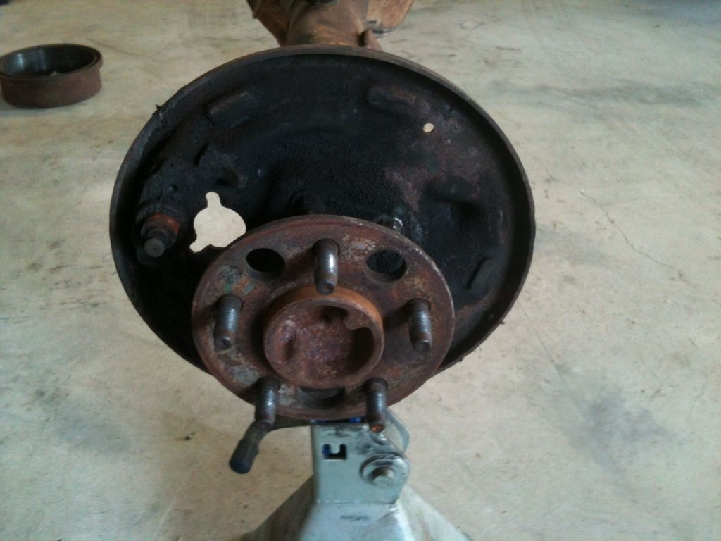
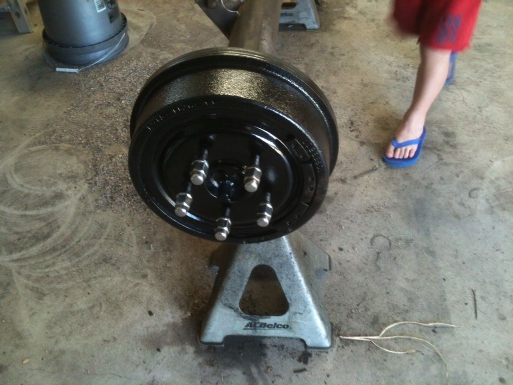
Workin the Rear
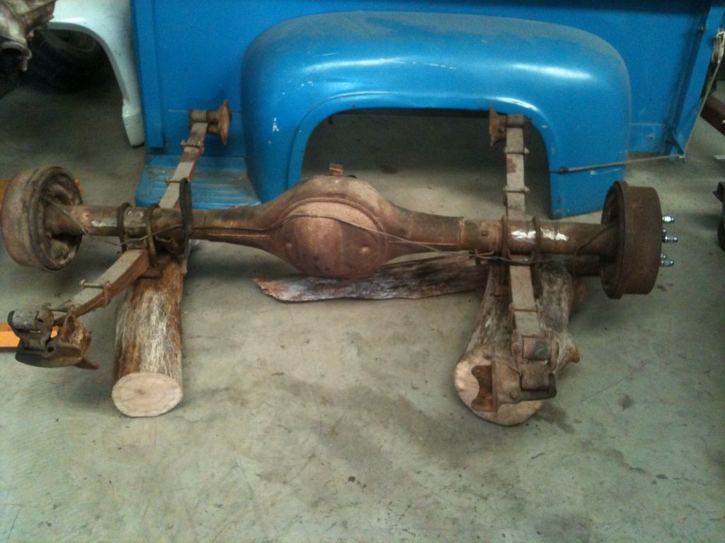
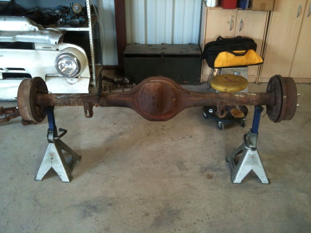
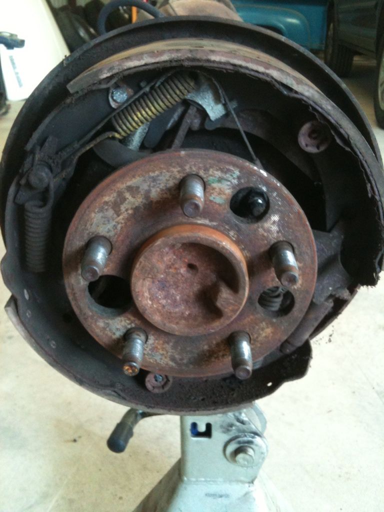
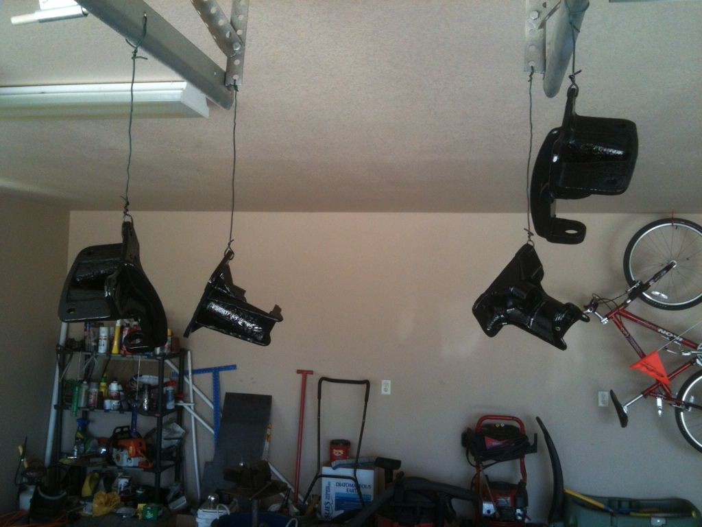
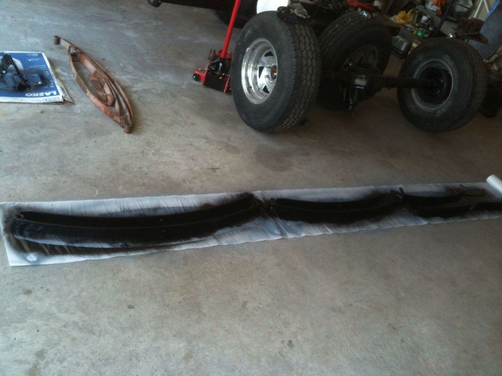
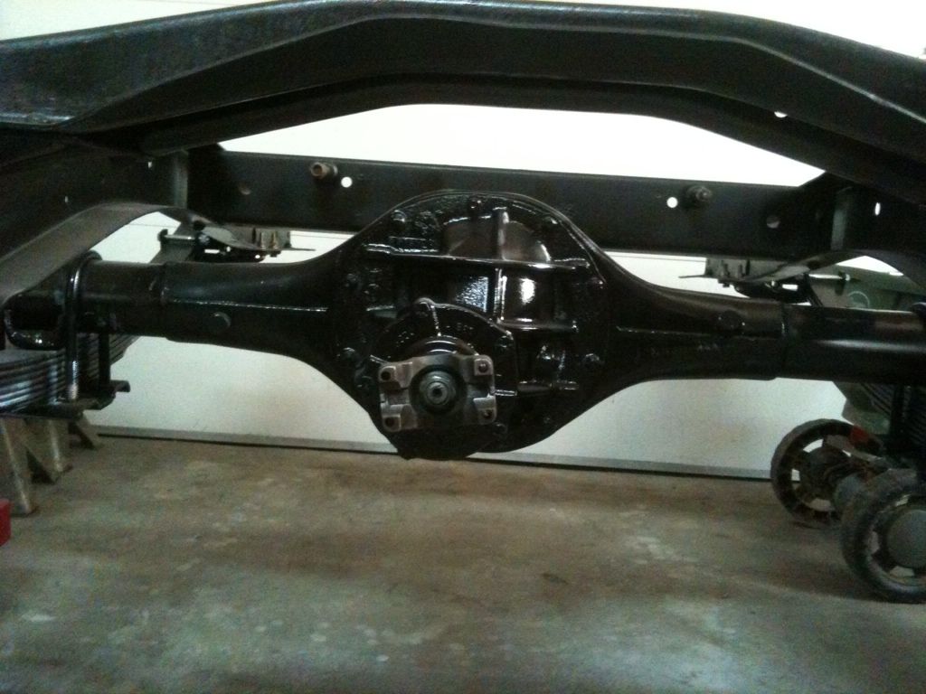
Last week and this weekend I started working over the 9 inch from the donor. The only issue I saw with this was a leak in the pinion seal. I took the yoke off cleaned and inspected the pinion bearing and added a new pinion seal. The drum brakes look great. The only thing I am replacing here is the wheel cylinder. The pads look almost new. I took both 31 spline axles out to inspect the axle bearings and gain access tot he backing palce for cleaning and painting. The axle bearings look great. This rear end was behind a 255 V8 and C4 trans. I do not think this rear end was ever worked hard according to my inpsection. I cleaned up both sides and started wire brushing the axle housing. This week I will finish up cleaning the 3rd member and paint the axle housing.
My boy wanted a few photo ops.
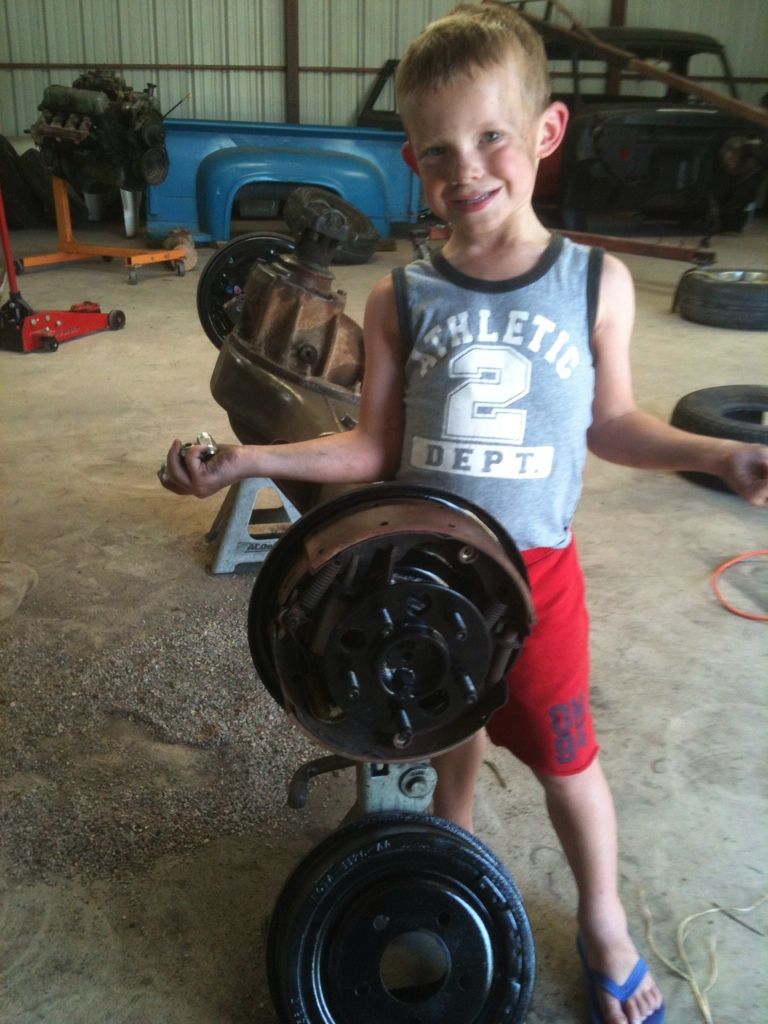
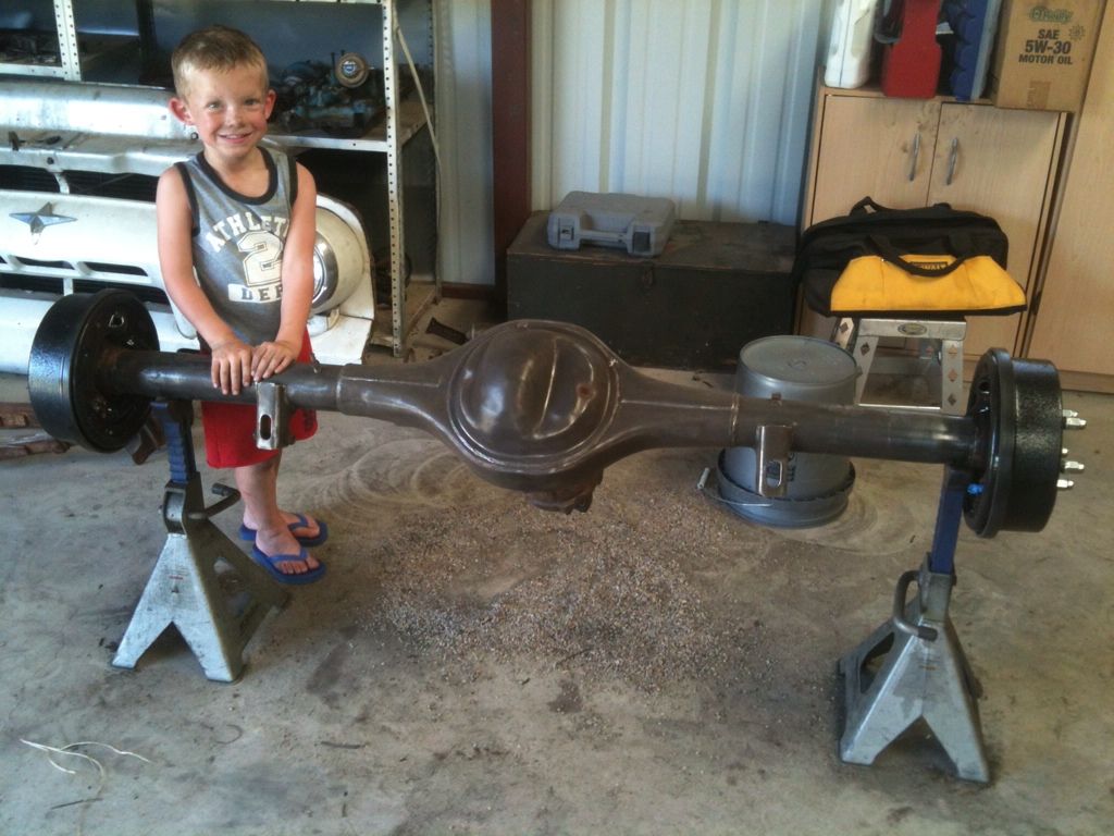
My boy wanted a few photo ops.
#42
07-09-2012, 02:19 PM
Elder User
Join Date: Jan 2008
Location: Gibsonia, PA
Posts: 803
Likes: 0
Received 0 Likes
on
0 Posts


#43
07-28-2012, 08:12 PM
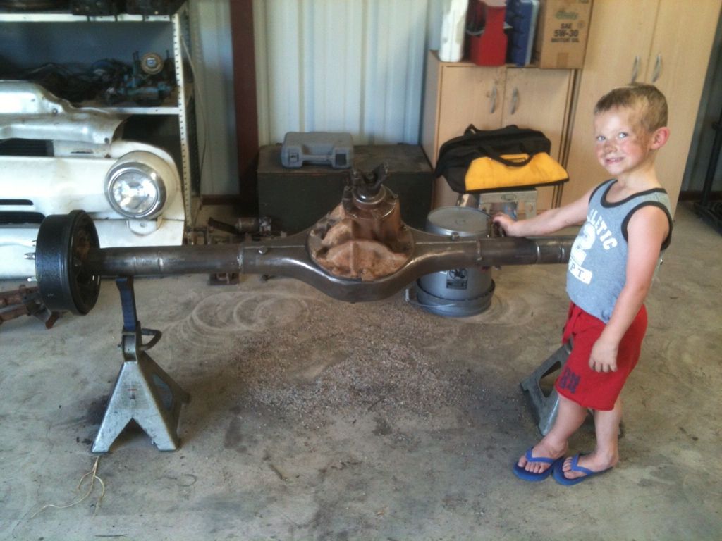
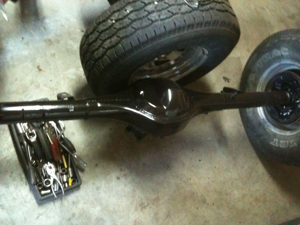
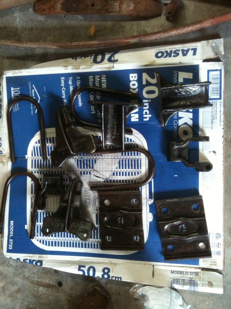
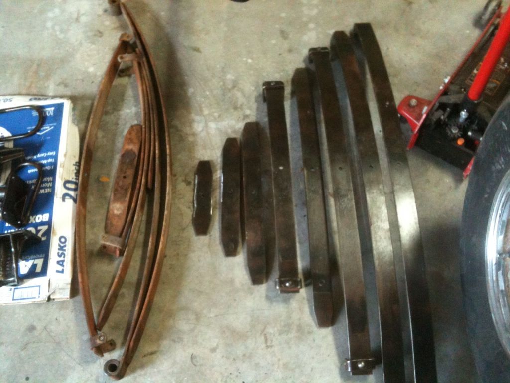
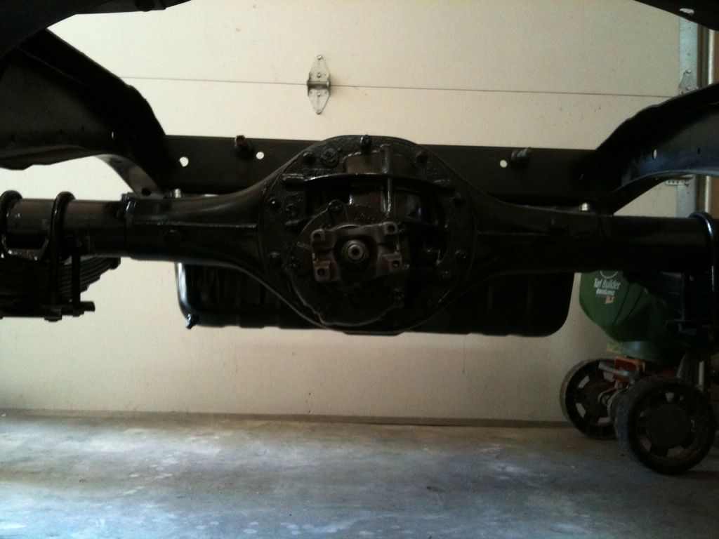
Rear End cont.
Friends,
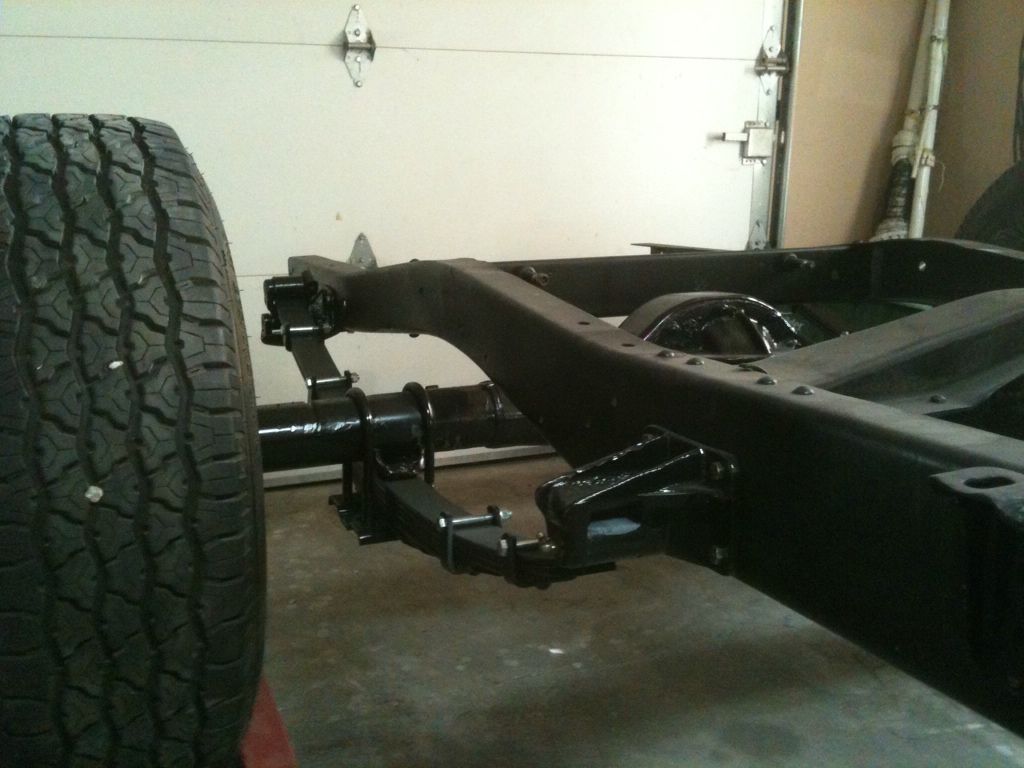
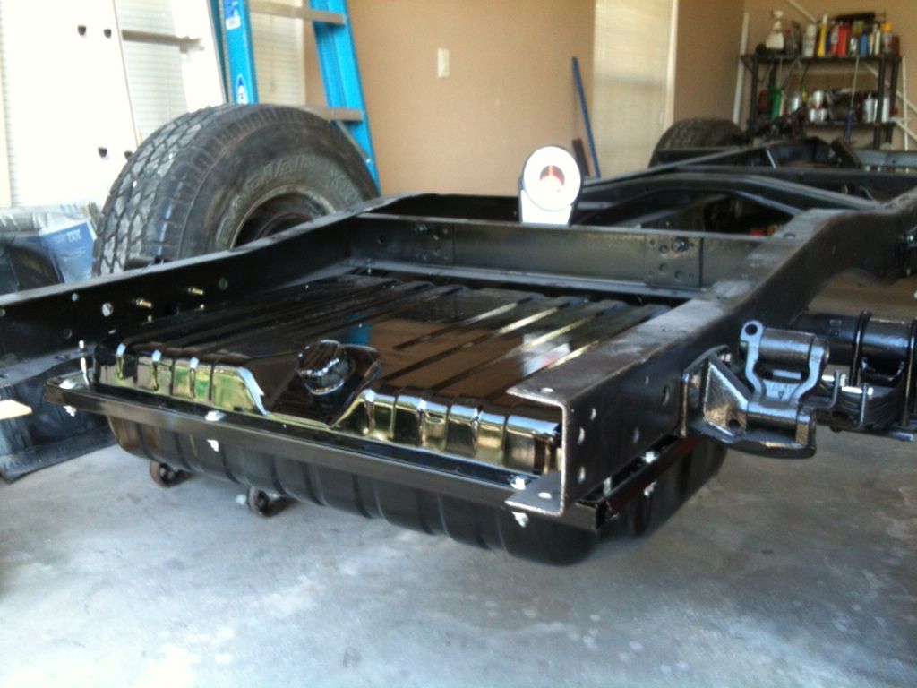
Below are pictures of some recent work. I installed the housing above the leafs for now. I want a lower than stock stance but realize that 2 1/4'' clearance with no load is not good. I did not weld anything knowing this may change. On some parts I used rust converter before primer and paint for the first time. It seems to work good. There is 4.5 degrees nose up as it sits. Tomorrow I will mount the gas tank (painted today). After that I will be rebuilding the C4.
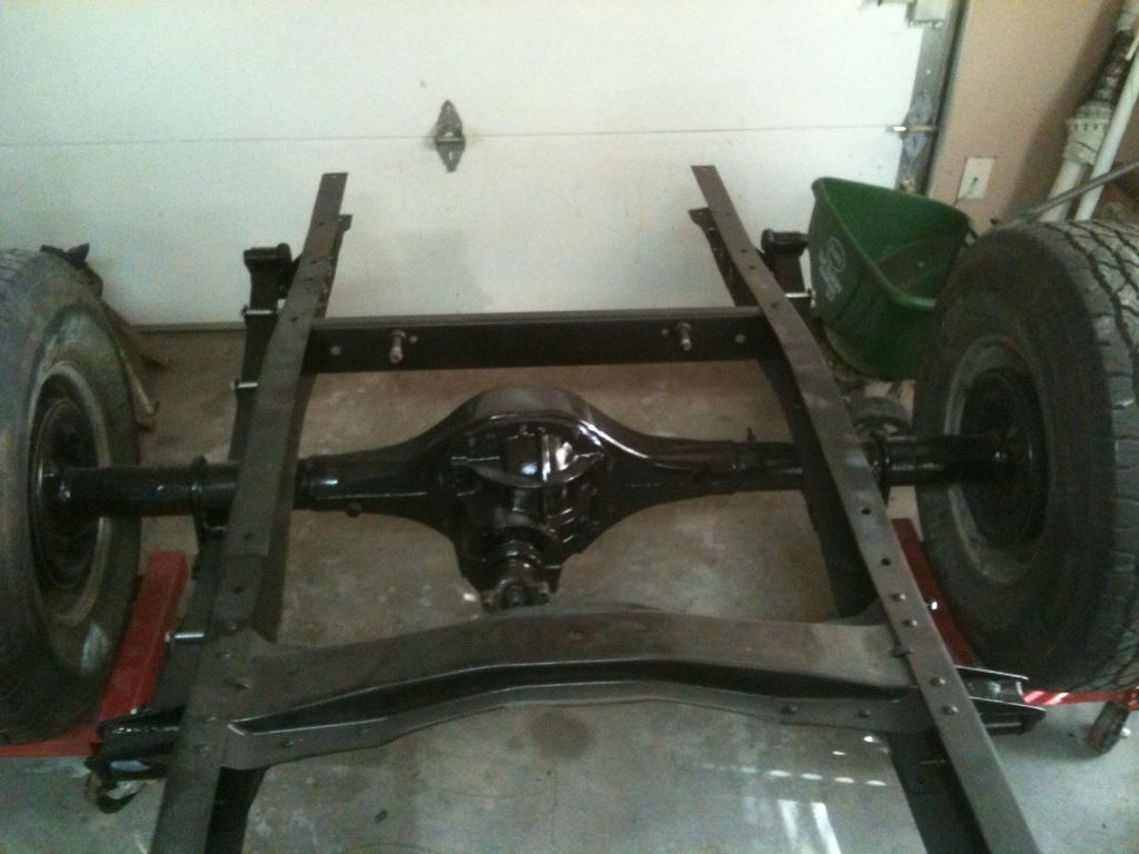
Below are pictures of some recent work. I installed the housing above the leafs for now. I want a lower than stock stance but realize that 2 1/4'' clearance with no load is not good. I did not weld anything knowing this may change. On some parts I used rust converter before primer and paint for the first time. It seems to work good. There is 4.5 degrees nose up as it sits. Tomorrow I will mount the gas tank (painted today). After that I will be rebuilding the C4.
#44
07-29-2012, 10:27 AM
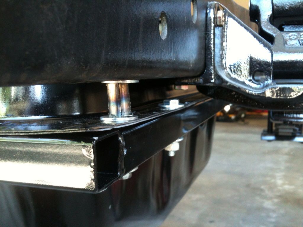
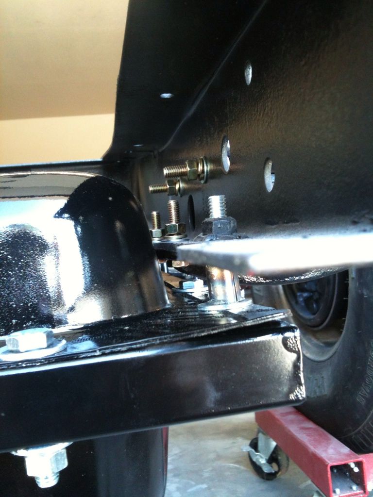
Gas Tank Install
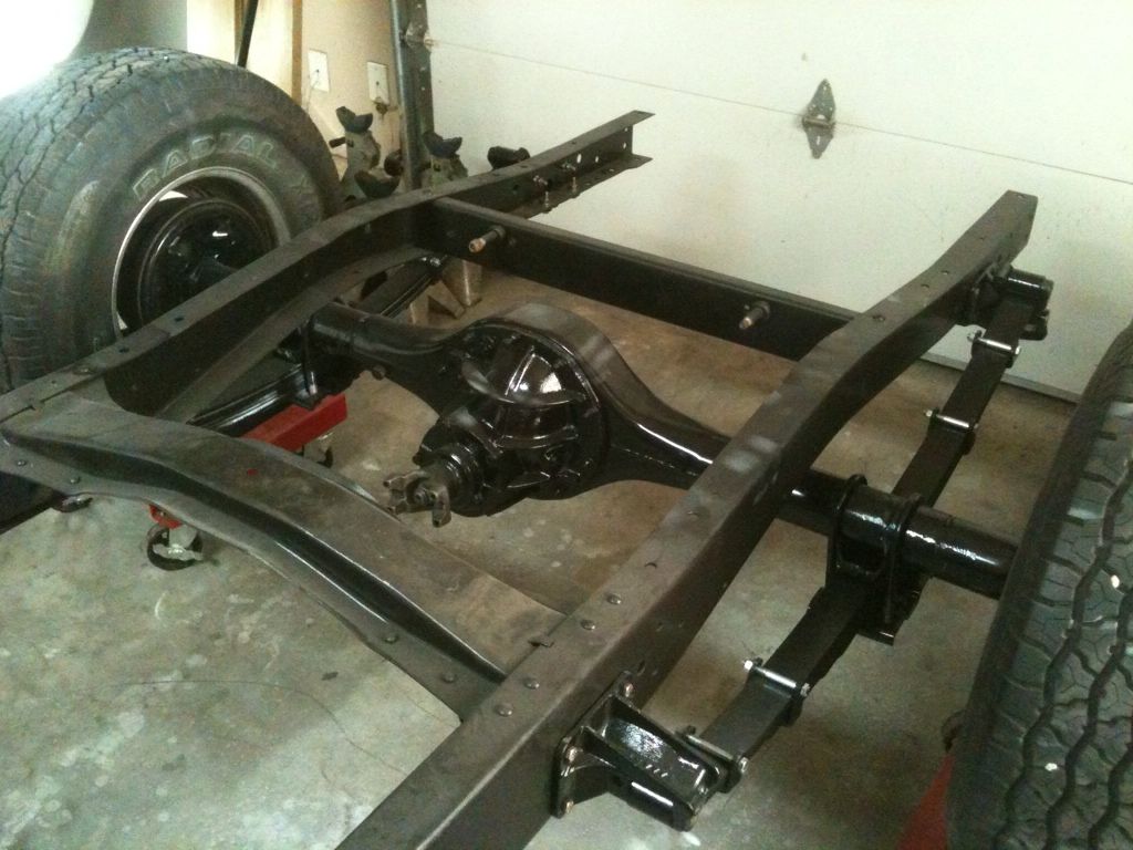
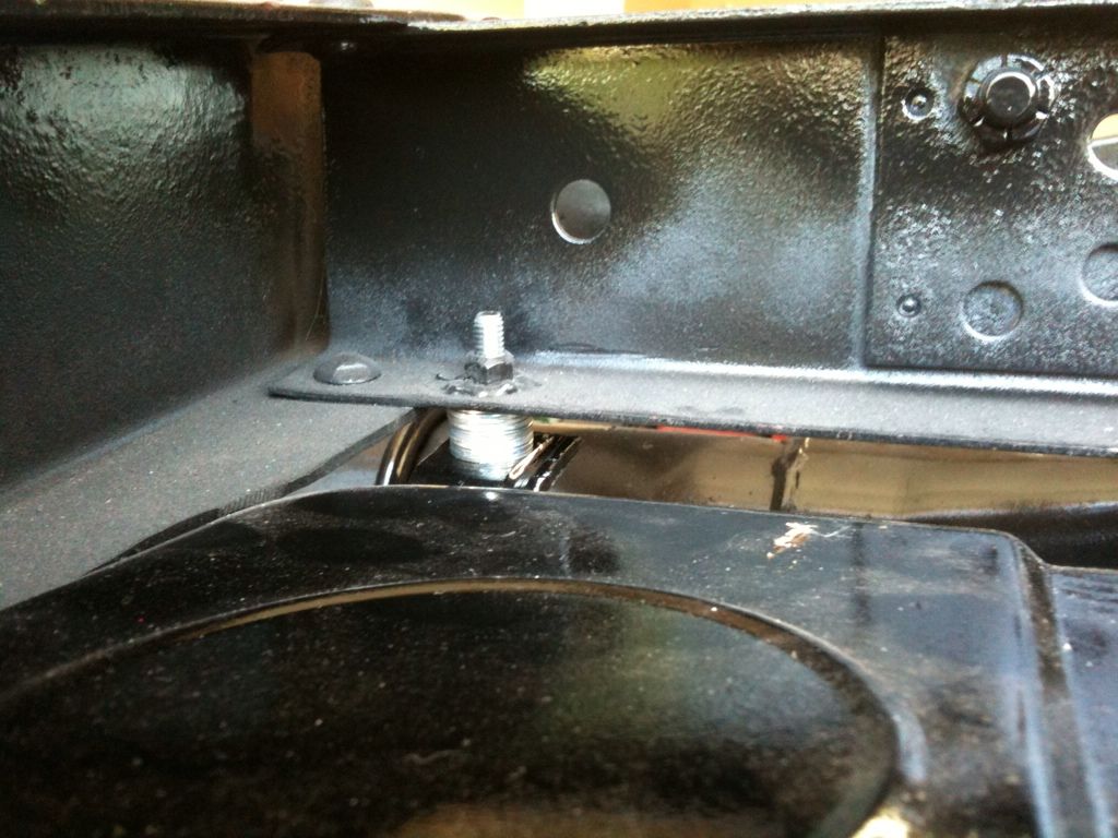
This a.m. I installed the gas tank (1970 Mustang 22 gal.). To clear the leaf hanger I needed to add space between the bottom of the frame and the top of the tank. Pretty easy and solid install. However, looking at the last photo the tank is as low as the rear housing so this may be another reason for me to put the housing back under the leafs.
#45
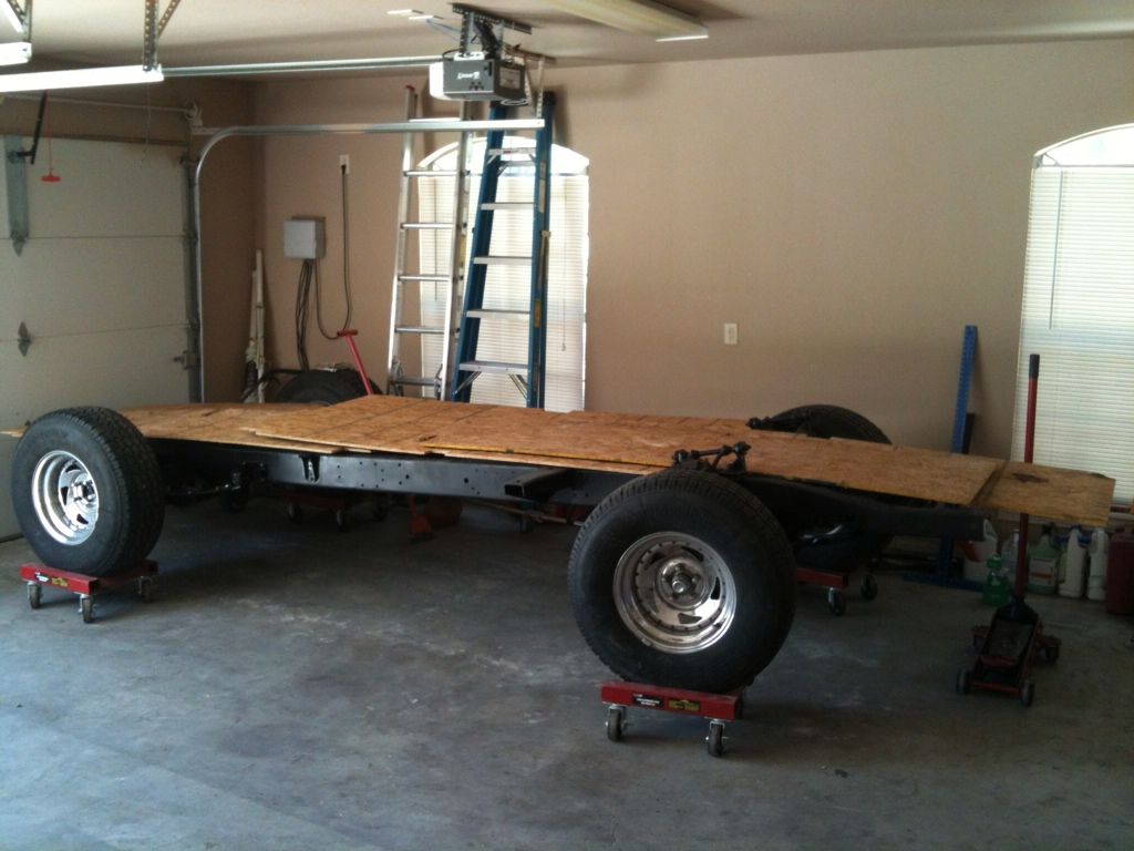
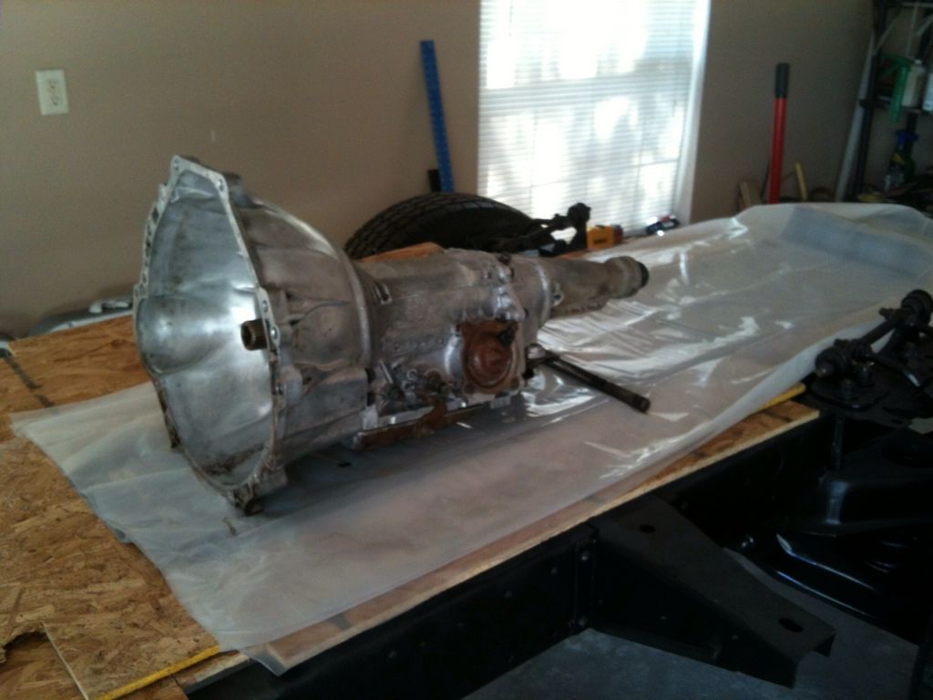
07-30-2012, 07:10 AM
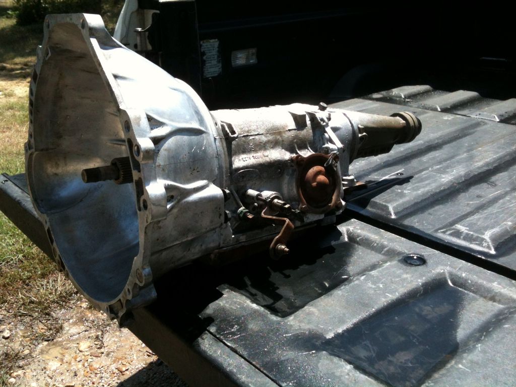
Trans Rebuild Prep
So after installing the gas tank I decided to make some head-way on the transmission reuild. Step 1, according to the Haynes Tech Manual for overahuling the Ford Automatic Trans is to build a table to lay all the parts out. So I made a table out of an "old truck frame" I had sitting around. The cool thing about this table is that I can roll it around the garage. Sweet! Step 2 is to clean the dirt off the trans before rebuild. I used an old tooth brush and some elbow greece and "wal-ah" she is ready for step 3. More to come.