Buildup! '03 Crown Vic IFS into '58 F100
#16
 12-28-2011, 11:40 PM

Join Date: Oct 2011
Posts: 263
Likes: 0
Received 0 Likes
on
0 Posts
I thought so too. I want this to be a "looks like a '58, but doesn't act like one" kind of truck. I want all the interior and exterior to not significantly differ from a '58 and when I pop the hood I want people's eyes to pop out and ask me a million questions. "How did you do that?" "What gave you that idea?" "What is that front suspension out of?" Oh the joys of hot roddin'. And yes I am having fun because I've been looking forward to this for months.
#17
12-29-2011, 08:34 AM
Well you are quite the artist aren't you?  My drawings look almost that good. Anyway I would look into the bearing kit spoke of in a previous post. My truck uses a rag joint between the column and steering box. I am not familiar with utilizing an old column like yours with modern componets. Must be fairly common as they have made a lower bearing kit for the conversion. Even with that it wouldn't be a bad idea to use a pillow block to support the bottom of the shaft.
My drawings look almost that good. Anyway I would look into the bearing kit spoke of in a previous post. My truck uses a rag joint between the column and steering box. I am not familiar with utilizing an old column like yours with modern componets. Must be fairly common as they have made a lower bearing kit for the conversion. Even with that it wouldn't be a bad idea to use a pillow block to support the bottom of the shaft.
#18
12-29-2011, 05:53 PM
Join Date: Oct 2011
Posts: 263
Likes: 0
Received 0 Likes
on
0 Posts
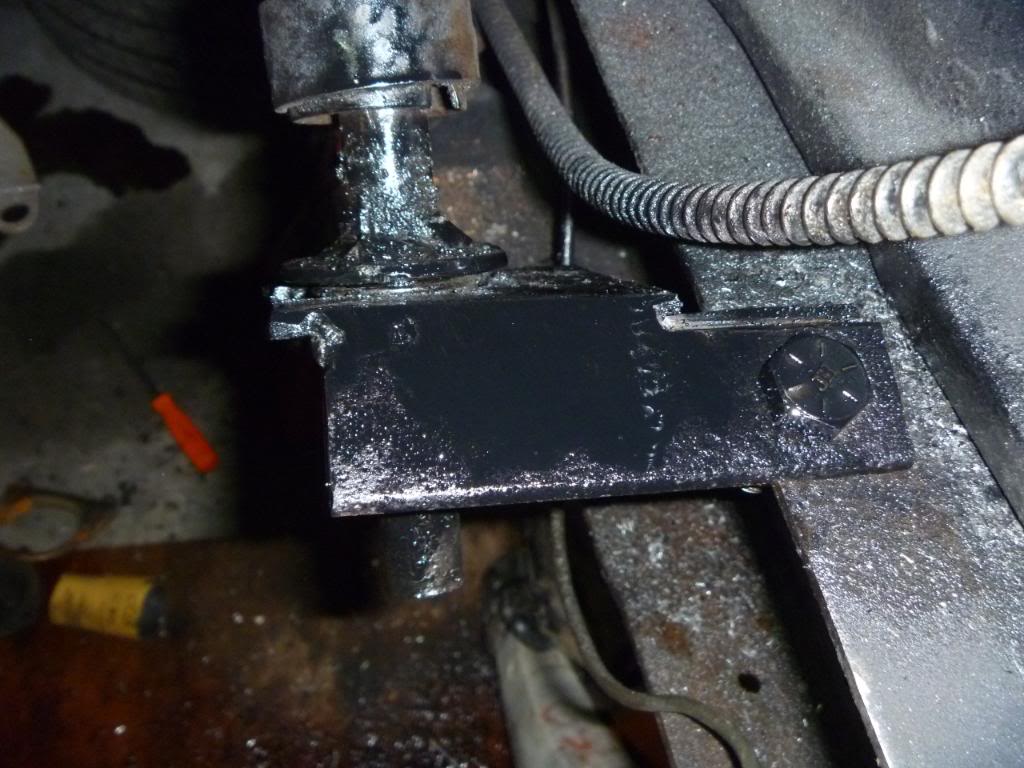
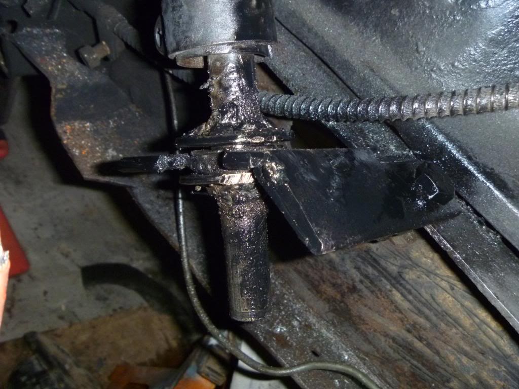
Haha I wouldn't quite call that art. My Engineering Graphics professor would probably call that crap, but like I said it was a quick drawing. I actually just got done with that bracket about thirty minutes ago. I just got a 3/4 inch bearing (that's the size of the shaft) and two 3/4 inch washers. I welded a piece of metal to the bearing and bolted a piece to the frame. I then welded those pieces together and the steering shaft is now stable. I'm about to go work on a bracket for the steering column.
#21
12-29-2011, 11:00 PM
Join Date: Oct 2011
Posts: 263
Likes: 0
Received 0 Likes
on
0 Posts
-DAY 4-
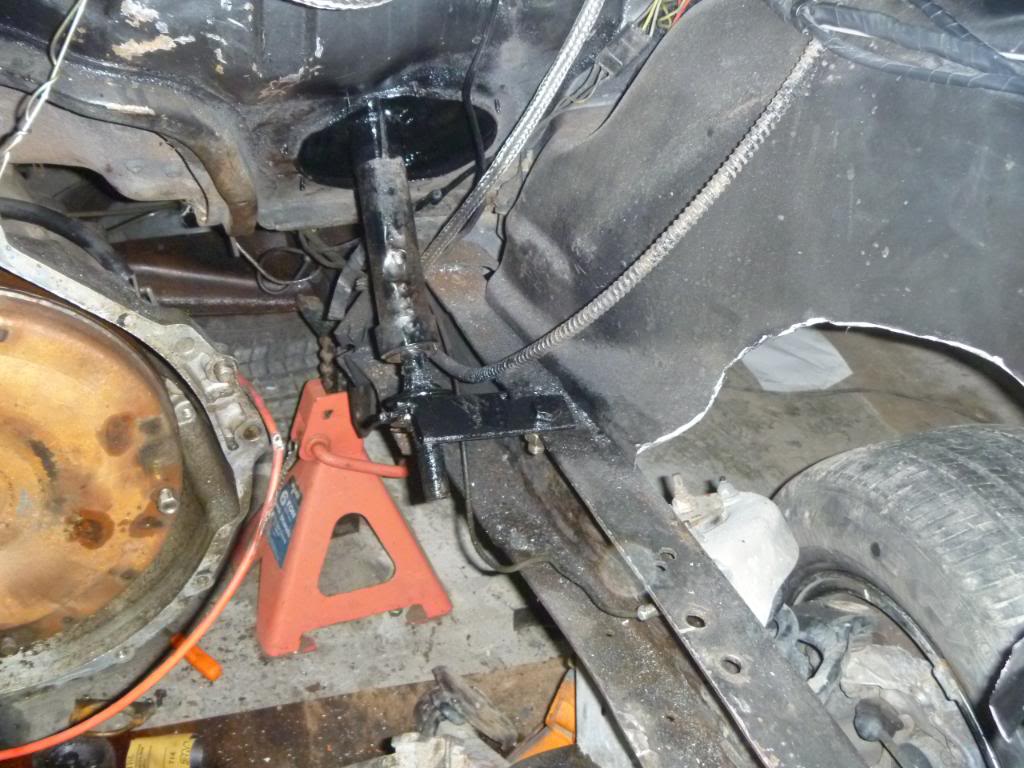
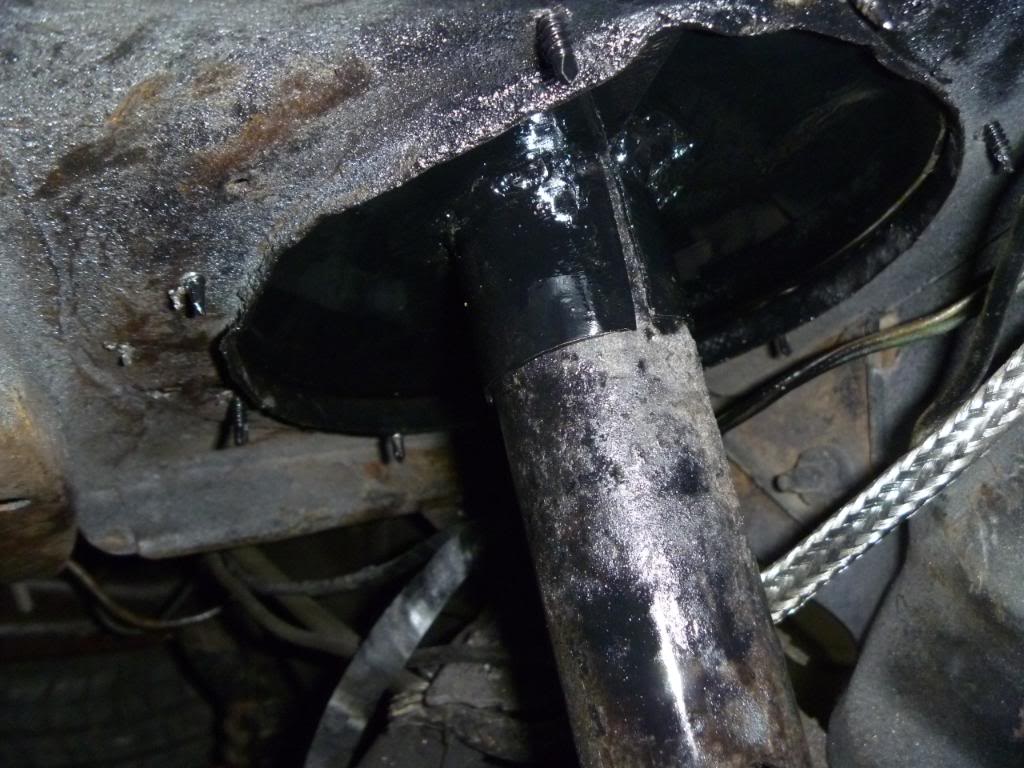
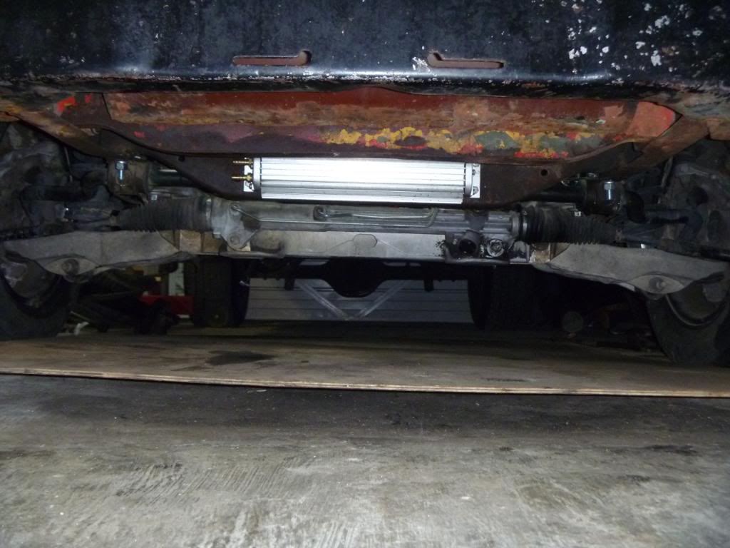
Here's what I got done today. I made a bracket to hold the steering shaft stationary while I turn the wheel. I also made a floor hole cover/steering column holder. I didn't have a cover for the hole before so this will be nice when I'm driving and air isn't blowing in from the floor. I made it out of 16 gauge steel and a 1.5 inch i.d pipe. I cut the pipe in half long ways and welded it to the plate I cut for the floor. It fits exactly to the steering column and also closes the hole that was in the floor from the factory. I also got the brake booster on. I went ahead and moved it over to where the clutch master cylinder was intended to go just to make sure I have plenty of room for the motor. While I was at it I made a plate to block off the hole where the brake master cylinder used to be.
 [/IMG]
[IMG]
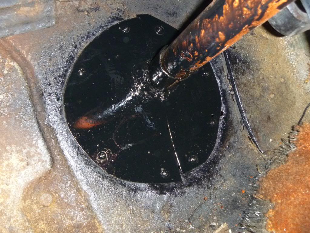
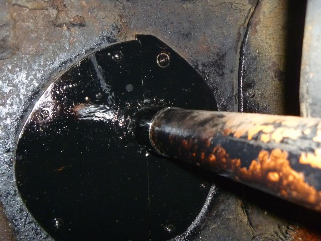
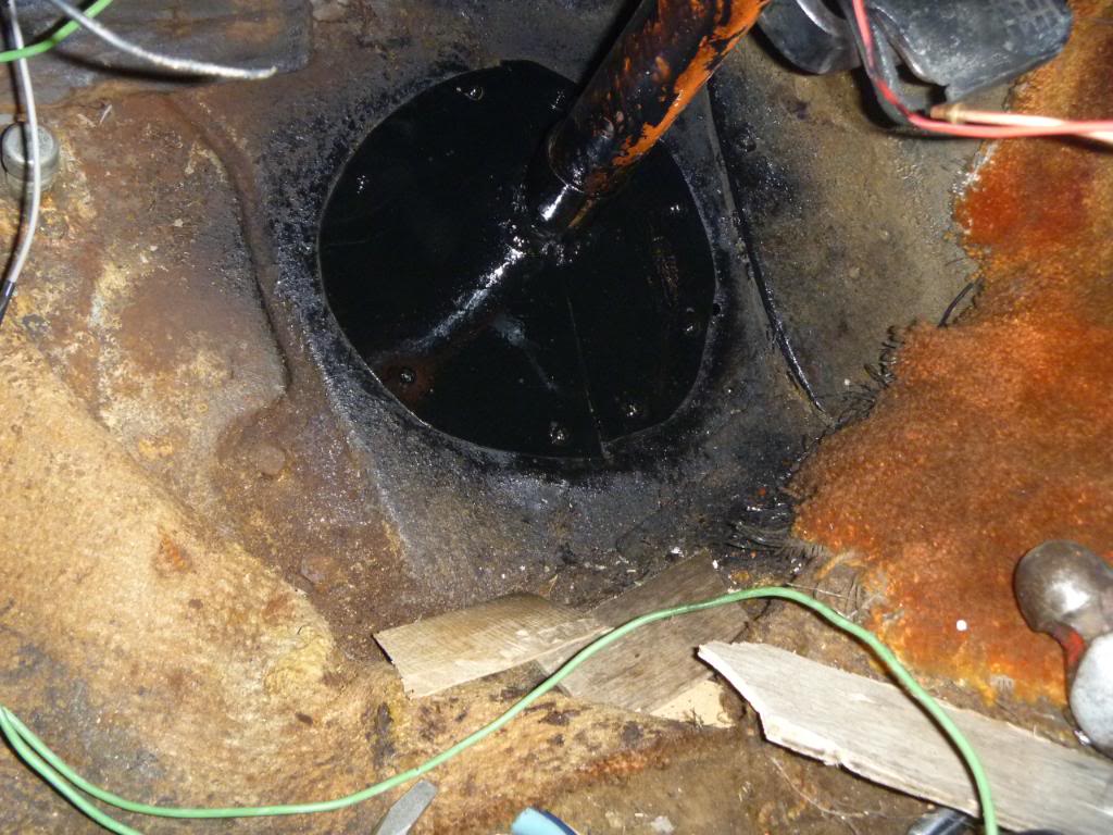
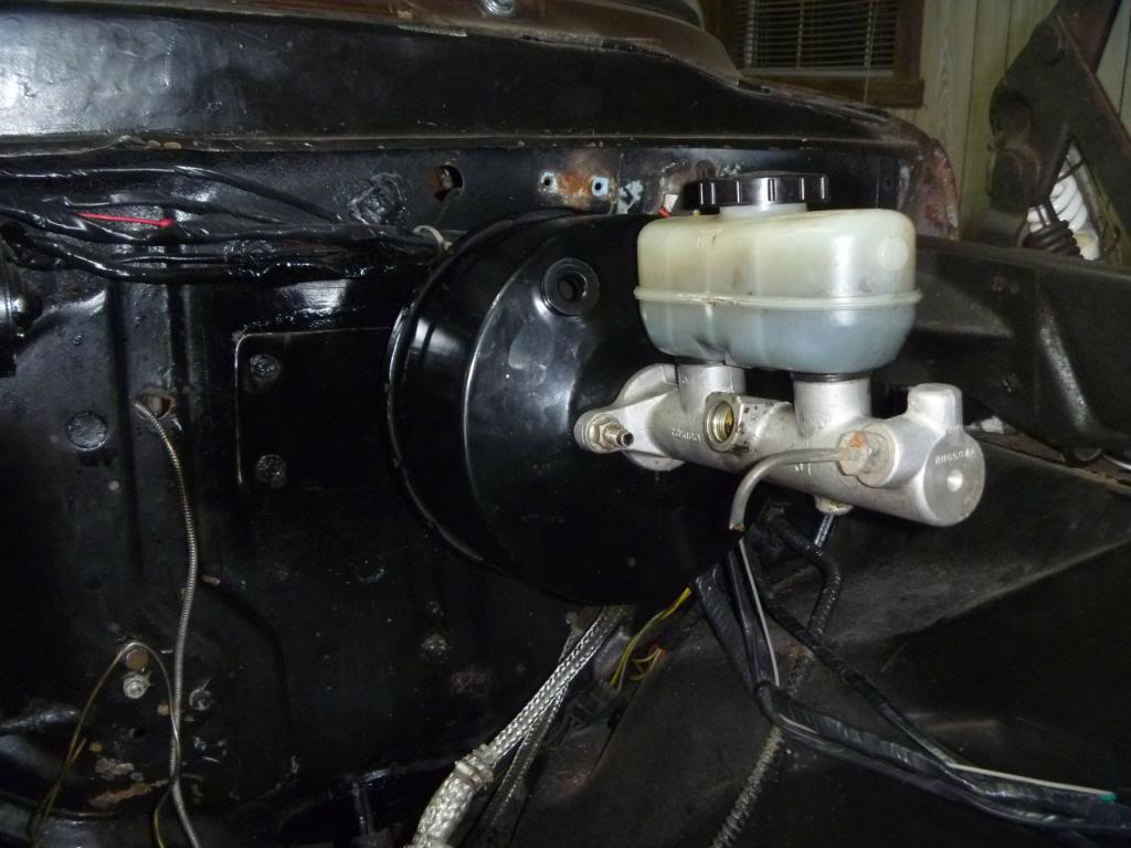
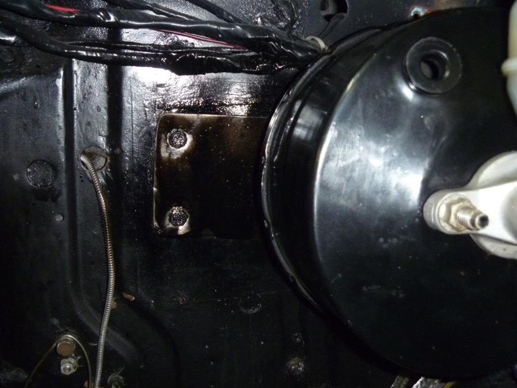
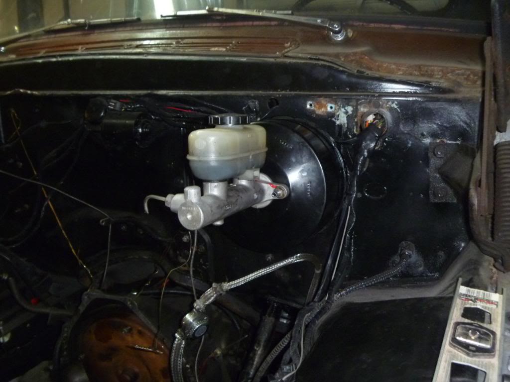
Here's what I got done today. I made a bracket to hold the steering shaft stationary while I turn the wheel. I also made a floor hole cover/steering column holder. I didn't have a cover for the hole before so this will be nice when I'm driving and air isn't blowing in from the floor. I made it out of 16 gauge steel and a 1.5 inch i.d pipe. I cut the pipe in half long ways and welded it to the plate I cut for the floor. It fits exactly to the steering column and also closes the hole that was in the floor from the factory. I also got the brake booster on. I went ahead and moved it over to where the clutch master cylinder was intended to go just to make sure I have plenty of room for the motor. While I was at it I made a plate to block off the hole where the brake master cylinder used to be.
[IMG]
#22
12-29-2011, 11:03 PM
Join Date: Oct 2011
Posts: 263
Likes: 0
Received 0 Likes
on
0 Posts
Now I need to figure out how to keep the brake pedal in the same location but still be able to work the brakes that is on the other side of the steering column. I think I stumbled across this once before on here so I will check and see if I can find it. If anyone has any ideas on how to fix this I sure would appreciate the suggestions.
#23
12-29-2011, 11:14 PM
Join Date: Oct 2011
Posts: 263
Likes: 0
Received 0 Likes
on
0 Posts
I just looked one of those up and I think I will tear off what I made today and use a pillow block. Even though what I made works, a pillow block looks much better. Thank you for the suggestion.
#24
12-30-2011, 08:14 AM

Is the column made fast to the floor as well as the frame? You might have some flexing issues. There needs to be a way for things to move around if you know what I mean, without stressing parts. The cab will be moving around on it's mounts, trying to take the column with it at the new bracket you made at floor level. That's why there was only rubber with sheetmetal covers there previously. Maybe you have thought of that but I didn't really see it in the pics.
#25
12-30-2011, 09:47 AM
They are not that expensive. The main issue I see with what you did is replacement down the road if the bearing goes bad. Since you now know what they look like you can see just fab a mount bracket and bolt it to it. They come in all kinds of setups. Just buy the one that works best for you.
#26
12-30-2011, 12:17 PM
Join Date: Oct 2011
Posts: 263
Likes: 0
Received 0 Likes
on
0 Posts
I got a grease able pillow block today and I will work on making the bracket either today or tomorrow.
The column is mounted solid to the floor but the shaft is the only thing held to the frame. This will allow the column to move around the shaft when necessary. It shouldn't be a problem but I could be wrong. I guess we'll find out when I drive it. 
Is the column made fast to the floor as well as the frame? You might have some flexing issues. There needs to be a way for things to move around if you know what I mean, without stressing parts. The cab will be moving around on it's mounts, trying to take the column with it at the new bracket you made at floor level. That's why there was only rubber with sheetmetal covers there previously. Maybe you have thought of that but I didn't really see it in the pics.
#27
12-30-2011, 02:46 PM
#28
12-30-2011, 05:14 PM
Join Date: Oct 2011
Posts: 263
Likes: 0
Received 0 Likes
on
0 Posts
Yeah I think the bearing might have came with a collar and a set screw. I'm not to certain. But yeah I don't think I will weld it if I can keep from it. I like the fact that it's grease-able because it will last longer than a non grease-able bearing. Plus the pillow block is rounded and smooth so if I do it right it will look like something they might would have used in the factory. I like that. I never pass up an opportunity to make something look like factory.
#29
12-30-2011, 05:32 PM
Join Date: Oct 2011
Posts: 263
Likes: 0
Received 0 Likes
on
0 Posts
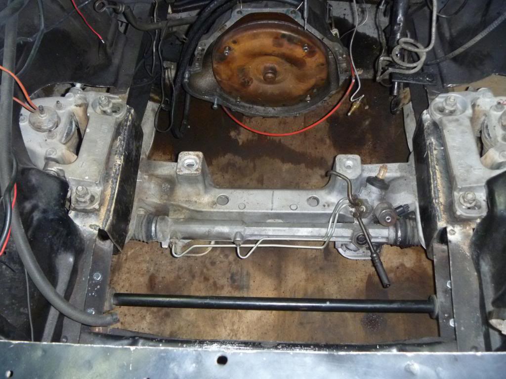
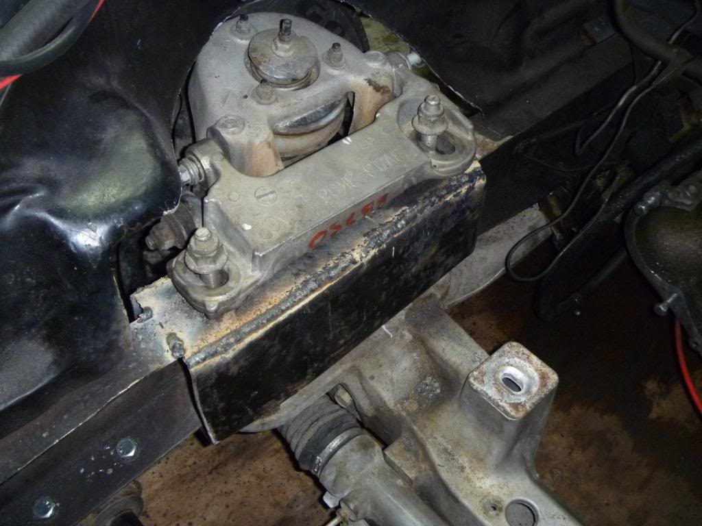
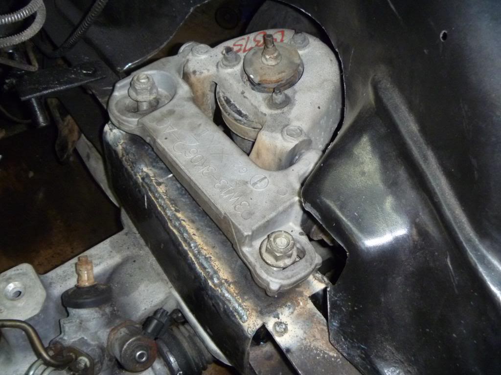
-DAY 5-
Spent the entire day placing the X member in the correct place and aligning it correctly. We finally put the holes in the frame for the alignment stubs and from there we put the holes for the spacers in the top and bottom of the frame. That takes a lot longer than you would think. I don't remember if I said this already or not, but I am using the 15" or so frame section that the spacers are in on my truck. I cut the top off of each frame section and took it off with the spacers still attached. By doing that I can slide the whole frame section (minus the top) over the truck frame then slide the top/spacer section into the frame and weld it back together. This allows me to have the exact correct spacing intended from the factory and it gives me a nice flat surface on the bottom to mount the X member to. As ya'll know the 57-60 truck frames bend right where you mount the CV IFS to. After I get the top welded back on, I can weld the whole frame section to my truck frame. This will make for a good strong, factory correct, mounting surface for the IFS. Some of you may think using the car frame section is a bad idea but in my eyes it's a win win. I don't have to guess about the spacing, I don't have to fabricate a shim to level off the X member (which eliminates a possibility of error), and I will have the strength of the CV frame PLUS the strength of my truck frame in that section. As far as looks I can use 1/4" steel to finish boxing the frame while at the same time blending in the car frame. When I am finished I plan on the car frame section disappearing. It will all be smooth and painted black.
Spent the entire day placing the X member in the correct place and aligning it correctly. We finally put the holes in the frame for the alignment stubs and from there we put the holes for the spacers in the top and bottom of the frame. That takes a lot longer than you would think. I don't remember if I said this already or not, but I am using the 15" or so frame section that the spacers are in on my truck. I cut the top off of each frame section and took it off with the spacers still attached. By doing that I can slide the whole frame section (minus the top) over the truck frame then slide the top/spacer section into the frame and weld it back together. This allows me to have the exact correct spacing intended from the factory and it gives me a nice flat surface on the bottom to mount the X member to. As ya'll know the 57-60 truck frames bend right where you mount the CV IFS to. After I get the top welded back on, I can weld the whole frame section to my truck frame. This will make for a good strong, factory correct, mounting surface for the IFS. Some of you may think using the car frame section is a bad idea but in my eyes it's a win win. I don't have to guess about the spacing, I don't have to fabricate a shim to level off the X member (which eliminates a possibility of error), and I will have the strength of the CV frame PLUS the strength of my truck frame in that section. As far as looks I can use 1/4" steel to finish boxing the frame while at the same time blending in the car frame. When I am finished I plan on the car frame section disappearing. It will all be smooth and painted black.
#30
12-31-2011, 08:03 PM
Join Date: Oct 2011
Posts: 263
Likes: 0
Received 0 Likes
on
0 Posts
-DAY 6-
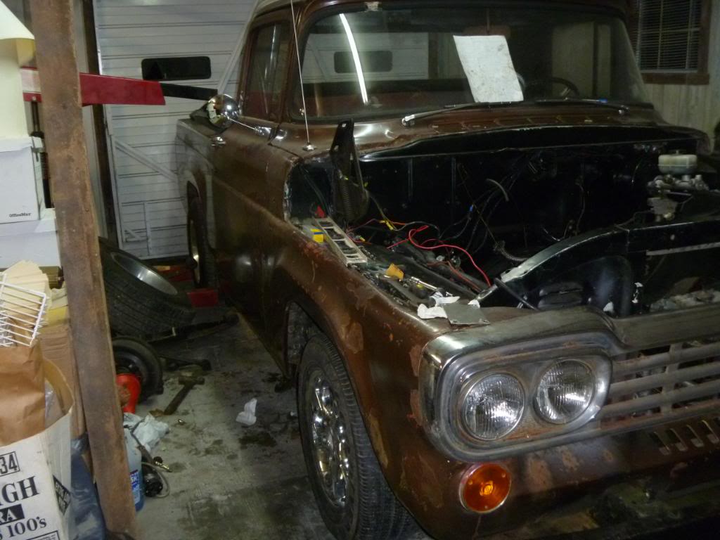
I finally got it in today. Boy does it feel good to finally get the truck back on the ground. And it sits quite a bit lower than before which is A-okay with me. I'm very happy with it. Now I just have minor things to worry about compared to what we have been doing.
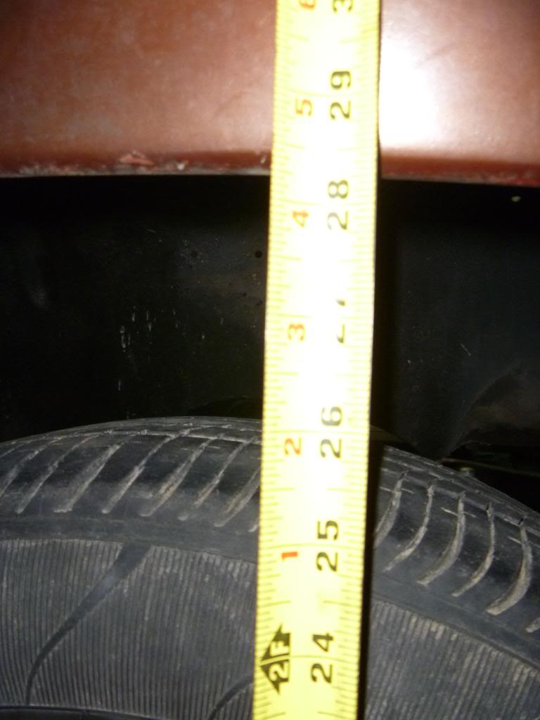
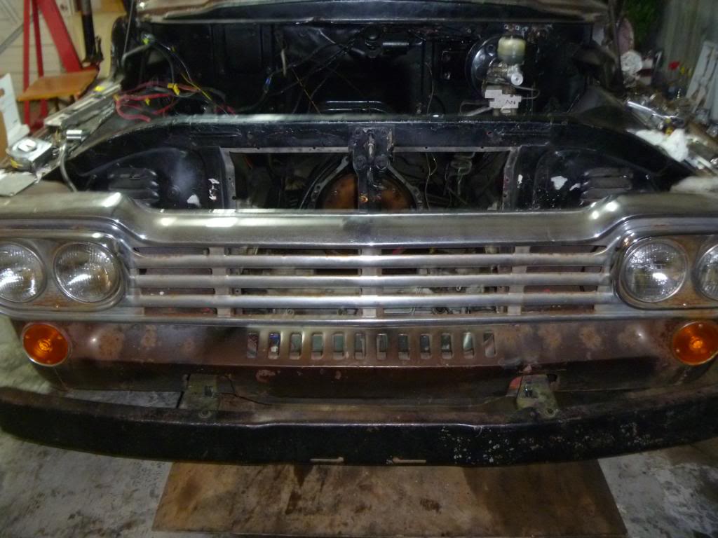
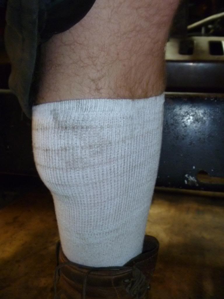
My sock comes up to the top of the bumper
 [/IMG]
I finally got it in today. Boy does it feel good to finally get the truck back on the ground. And it sits quite a bit lower than before which is A-okay with me. I'm very happy with it. Now I just have minor things to worry about compared to what we have been doing.
My sock comes up to the top of the bumper