


Computer Pinout Diagram?
Thread Starter
|
Tuned
Joined: Sep 2011
Posts: 416
Likes: 0
Computer Pinout Diagram?
Hey all. Im dropping a 79 F250 on a 95 Powerstroke. I was wondering if anyone had or knew of where I could find a pinout diagram of the computer on a 95 and a list for the pinouts? I have attached an example.
When I put a TBI 350 in my Jeep CJ I just used the harness how it came out of the chevy and where the it use to get 12v ignition from the chevy I just rewired that from the jeep ignition and also gave it its normal 12v to the power block with all the relays etc.
Will I be able to do the same type of thing here? Just jump the 12v that use to go to the I of the starting solenoid to the ignition wire of the computer with a 12v relay for better power? Then once the computer is powered it will run the fuel pump and the motor etc.??
Example:
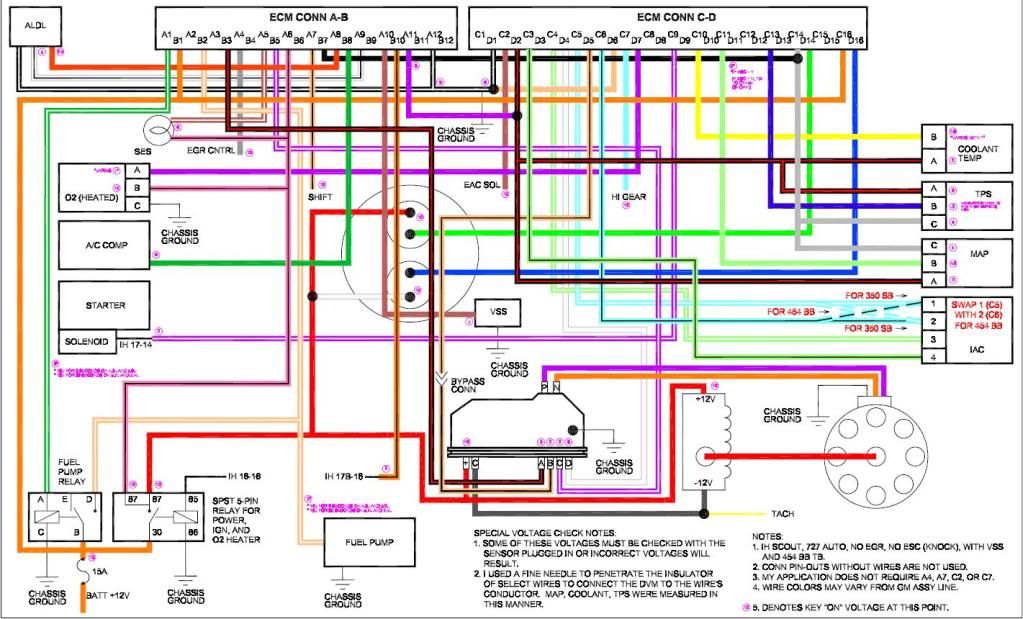
A1- grn/wht- this wire is used to energize the fuel pump relay.
A2- not used
A3- not used
A4- gry- to EGR relay.(optional) This is a ground from the ECM to control the EGR relay.
A5- brn/wht- SES(service eng soon) light. This is a ground to turn on the light.
A6- pnk/blk- switched 12v from the ignition relay.
A7- not used
A8- orn- ALDL Serial data. This is your ALDL pin E data for your lap top.
A9- wht/blk- ALDL pin B diag mode. When jumpered to ground will set the ECM to ALDL diagnostic mode.
A10- brn- VSS speed sensor signal to the ECM (optional)
A11- ppl or blk- MAP sensor ground.
A12- blk/wht- System ground. Can be tied with D1. Goes to engine ground.
Just to clear the confusion on which pins are grounds I have taken a C3 ECM apart and labeled the pin locations on the plugs.
If you look you can see that D1 and D2 are solder connected and A11 and A12 are also connected.
So if either one of the two, example: D1 and A11 are grounded the other one will be. D2 and A12.
SEE PIC BELOW
B1- orn- 12v fused from battery. I use an inline fuse on this. It also ties into C16.
B2- tan/wht- Fuel pump signal from the relay. This one ties into several places, the fuel pump, the relay, and the ecm. When the relay is on it sends 12v thru this wire to turn on the fuel pump, at the same time it tells the ECM the fuel pump is on.
B3- blk/red- EST reference.
B4- not used
B5- ppl/wht- EST high reference
B6- not used
B7- blk- ESC signal This is the knock sensor signal to the ECM. The knock sensor circuit is optional. If not used, tie this wire to C14 the 5v reference. This will fool the system sometimes but you will need to program the chip to prevent the SES light from coming on.
B8- dk grn- AC signal. This tells the ECM that the AC is turned on. This can be used to set the idle speed higher when you turn the AC on. I use it to increase the idle when using the compressor for on board air. Same thing!! Just tie it to the wire going to the AC clutch.
B9- not used
B10-orn/blk- Park/Neutral sw. This is optional but I have hooked it into the park sw on the tranny. It tells the ECM when you are in Pk or N. It can be used to give a slight adjustment to idle speed when switching from park to drive and back.
B11- not used
B12- not used
C1- not used
C2- not used
C3- IAC- Idle air control
C4- IAC
C5- IAC
C6- IAC -The ECM controls the IAC motor. It adjust the amount of air that is bypassed around the butterflies to adjust the idle speed.
Note: (For the IAC pins C5 and C6 are reversed on the 454 vs the SBC so swap those 2 pins if using a 454 TB with the bolt on IAC.)
C7- not used
C8- not used
C9- ppl/wht- Starter crank signal. Goes to the small terminal of the starter. The stock scout wire is white that goes there. Tells the ECM you are trying to start the engine.
C10- yel- Temp sender signal
C11- lt grn- Map sensor signal
C12- (1228746 only) IAT/MAT sensor
C13- dk blu- TPS sensor signal
C14- gry- 5v reference signal to map and TPS.
C15- grn- inj B ground signal. Most systems do not use this. It was used on some of the bigger engines to share the load of the injector signal.
C16- orn- fused 12v tied to B1
D1- blk/wht- System ground, ties to A12 and engine.
D2- blk- Sensor ground. To eng block or head.
D3- not used
D4- wht- EST control
D5- tan/blk- EST bypass. This is the wire that has a plug near the distr that you disconnect to set your timing.
D6- Tan- O2 ground to engine.
D7- ppl- O2 sensor signal
D8- D13 not used
D14- lt grn- Injector B ground signal
D15- blu- optional injector A ground signal
D16- blu- Injector A ground signal
Thanks alot!
When I put a TBI 350 in my Jeep CJ I just used the harness how it came out of the chevy and where the it use to get 12v ignition from the chevy I just rewired that from the jeep ignition and also gave it its normal 12v to the power block with all the relays etc.
Will I be able to do the same type of thing here? Just jump the 12v that use to go to the I of the starting solenoid to the ignition wire of the computer with a 12v relay for better power? Then once the computer is powered it will run the fuel pump and the motor etc.??
Example:
A1- grn/wht- this wire is used to energize the fuel pump relay.
A2- not used
A3- not used
A4- gry- to EGR relay.(optional) This is a ground from the ECM to control the EGR relay.
A5- brn/wht- SES(service eng soon) light. This is a ground to turn on the light.
A6- pnk/blk- switched 12v from the ignition relay.
A7- not used
A8- orn- ALDL Serial data. This is your ALDL pin E data for your lap top.
A9- wht/blk- ALDL pin B diag mode. When jumpered to ground will set the ECM to ALDL diagnostic mode.
A10- brn- VSS speed sensor signal to the ECM (optional)
A11- ppl or blk- MAP sensor ground.
A12- blk/wht- System ground. Can be tied with D1. Goes to engine ground.
Just to clear the confusion on which pins are grounds I have taken a C3 ECM apart and labeled the pin locations on the plugs.
If you look you can see that D1 and D2 are solder connected and A11 and A12 are also connected.
So if either one of the two, example: D1 and A11 are grounded the other one will be. D2 and A12.
SEE PIC BELOW
B1- orn- 12v fused from battery. I use an inline fuse on this. It also ties into C16.
B2- tan/wht- Fuel pump signal from the relay. This one ties into several places, the fuel pump, the relay, and the ecm. When the relay is on it sends 12v thru this wire to turn on the fuel pump, at the same time it tells the ECM the fuel pump is on.
B3- blk/red- EST reference.
B4- not used
B5- ppl/wht- EST high reference
B6- not used
B7- blk- ESC signal This is the knock sensor signal to the ECM. The knock sensor circuit is optional. If not used, tie this wire to C14 the 5v reference. This will fool the system sometimes but you will need to program the chip to prevent the SES light from coming on.
B8- dk grn- AC signal. This tells the ECM that the AC is turned on. This can be used to set the idle speed higher when you turn the AC on. I use it to increase the idle when using the compressor for on board air. Same thing!! Just tie it to the wire going to the AC clutch.
B9- not used
B10-orn/blk- Park/Neutral sw. This is optional but I have hooked it into the park sw on the tranny. It tells the ECM when you are in Pk or N. It can be used to give a slight adjustment to idle speed when switching from park to drive and back.
B11- not used
B12- not used
C1- not used
C2- not used
C3- IAC- Idle air control
C4- IAC
C5- IAC
C6- IAC -The ECM controls the IAC motor. It adjust the amount of air that is bypassed around the butterflies to adjust the idle speed.
Note: (For the IAC pins C5 and C6 are reversed on the 454 vs the SBC so swap those 2 pins if using a 454 TB with the bolt on IAC.)
C7- not used
C8- not used
C9- ppl/wht- Starter crank signal. Goes to the small terminal of the starter. The stock scout wire is white that goes there. Tells the ECM you are trying to start the engine.
C10- yel- Temp sender signal
C11- lt grn- Map sensor signal
C12- (1228746 only) IAT/MAT sensor
C13- dk blu- TPS sensor signal
C14- gry- 5v reference signal to map and TPS.
C15- grn- inj B ground signal. Most systems do not use this. It was used on some of the bigger engines to share the load of the injector signal.
C16- orn- fused 12v tied to B1
D1- blk/wht- System ground, ties to A12 and engine.
D2- blk- Sensor ground. To eng block or head.
D3- not used
D4- wht- EST control
D5- tan/blk- EST bypass. This is the wire that has a plug near the distr that you disconnect to set your timing.
D6- Tan- O2 ground to engine.
D7- ppl- O2 sensor signal
D8- D13 not used
D14- lt grn- Injector B ground signal
D15- blu- optional injector A ground signal
D16- blu- Injector A ground signal
Thanks alot!

Lead Driver


Joined: Oct 2003
Posts: 8,476
Likes: 37
From: Madison, WI
For a project of this level, I'd recommend buying and EVTM - Electrical and Vacuum Troubleshooting Manual - for a '95. It contains all the diagrams for the truck, and you're gonna need 'em for the engine, tranny, dash, etc. There's gonna be a LOT to fab. You'll need a way/place to mount both the PCM and IDM, lots more fuses/relays than a '70s vintage truck would have (is there even an underhood fuse box in the "patient" truck?). What do you intend to do about gauges, speedo/odo, tach, etc?
Fellas have done it, at least going back to an '80s vintage truck. Not sure about '70s. There's a guy here in WI somewhere selling a PSD in something like a '61, but it's actually just the '61 cab and bed laid (somehow) on a "modern" frame.
Fellas have done it, at least going back to an '80s vintage truck. Not sure about '70s. There's a guy here in WI somewhere selling a PSD in something like a '61, but it's actually just the '61 cab and bed laid (somehow) on a "modern" frame.
Thread Starter
|
Tuned
Joined: Sep 2011
Posts: 416
Likes: 0
Thats exactly what Im doing. Putting the 78 body on the 95 frame. I will take the entire harness out of the 95. Including fuse boxes and everything to do with the computers. So once that is all out I will leave it just as it was and repower it all in the 78. What does each comp. do? One run just the motor and the other the whole truck?
The dash im still trying to figure out. I may try to pull the guage cluster out of the 78 and somehow make the 95 fit into the 78 dash. If not it will be an autometer aftermarket cluster made up or something. Someone just told me they had a friend who did this and put the whole 97 dash in there 73. That may be an option. Would rather keep the 78 tho.
Fabrication isnt an issue for the body mounts and fitting the radiator in etc. Got a welder and a plasma cutter
Where can I get one of those books? would you mind posting a link? I am actually brand new to diesels so it will be a learning process but I have 2 buddies that went to school for them helping me out as needed.
Like I said I already put an 88 fuel injected 350 in a 79 Jeep CJ. I know this is a bit more work but same general idea with adding a computer etc. to a non computer vehicle. But I'm allll ears for help and opinions for how to do the dash especially!
Thanks!

Hotshot


Joined: Jul 2003
Posts: 12,177
Likes: 40
From: Newport, WA
79oldbone, once you get 25 posts I'll send you a PM with some info for a site you can go to get all the wiring diagrams/info you need. Or if you want, shoot me an email to cowboyona426 at gmail dot com.
Senior User
Joined: Jan 2009
Posts: 353
Likes: 0
From: elk plain, wa
go to the ford dealer and get the engine controls cell and the tranny cell if you are running the auto, i would post everything up for you but i can get in trouble woth ford for taking it off there technition site and posting it for the world, it is really easy to wire the engine up, i just started with the pcm connector engine harness and all the sensors in the cab and started to build the harness, just time consumming, and when you make it triple check every wire cause it only takes one to be off then you are out a pcm or idm.
Senior User
Joined: Jan 2009
Posts: 353
Likes: 0
From: elk plain, wa
Trending Topics
Thread Starter
|
Tuned
Joined: Sep 2011
Posts: 416
Likes: 0
FTE Stories
Ford Trucks for Ford Truck Enthusiasts

2027 Ford Super Duty Buyer's Guide (Every Model, Engine, & Package)
Brett Foote
Top 10 Ford Truck Tragedies
Joe Kucinski
AEV FXL Super Duty - the Super Duty Raptor Ford Doesn't Make
Brett Foote
Lobo Vs Lobo: Proof the F-150 Lobo Should Be Even Lower!
Michael S. Palmer
Ford's 2001 Explorer Sportsman Concept Looks For a New Home
Verdad Gallardo
10 Best Ford Truck Engines We Miss the Most!
Joe Kucinski
2026 Shelby F-150 Off-Road: Better Than a Raptor R?
Brett Foote
2027 Super Duty Carhartt Package First Look: 12 Things You NEED to Know!
Michael S. Palmer
10 Most Surprising 2026 Ford Truck Features!
Joe Kucinski
Thread
Thread Starter
Forum
Replies
Last Post
oceanblues
1987 - 1996 F150 & Larger F-Series Trucks
6
Oct 16, 2018 10:58 AM
brookslion1
1980 - 1986 Bullnose F100, F150 & Larger F-Series Trucks
27
Jul 4, 2011 06:30 AM