Hedman Hedder install w/pics
#1
 08-10-2011, 06:15 PM

Hedman Hedder install w/pics
I bought my 2003 F-250 with 121k miles on the odometer, knowing it had a couple of broken exhaust studs. Now, at 130k, I noticed that there were more than a couple, so I decided it was time to address the issue. And since it’s such a big project, and new studs would probably just break again, I opted to ditch the logs and restrictive y-pipe, and upgrade to headers while I had everything apart. So, after a long search looking at reviews, prices, and difficulty of installation (bolt on vs. weld, need to clearance the frame, etc.), I decided to go with ceramic coated Hedman Hedders (part no. 89666). Hedman describes these as “shorty” headers. But, although they’re certainly not long tube units, they’re not exactly shorties, either. They’re actually more of a mid-length header, and should give the V10 a little boost in low end torque.
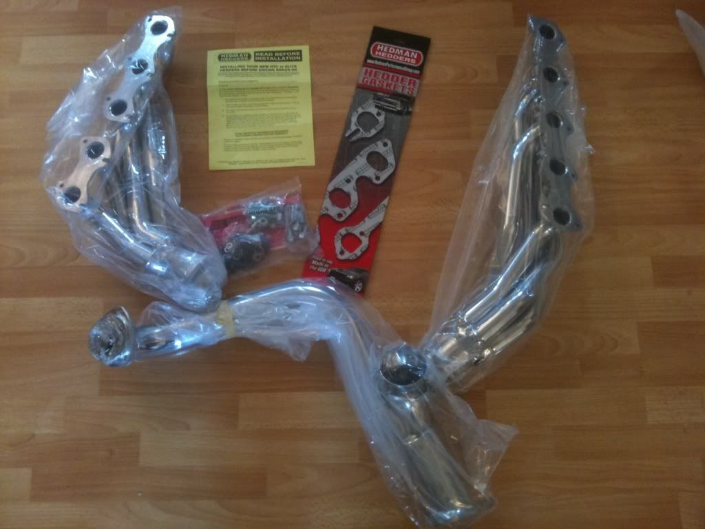
The new headers arrived in a single large box via FedEx. Upon opening it, it seemed that the box was too large, having enough empty space inside that the headers could easily slide around and bang into each other during shipping. But the y-pipe and both headers were each well wrapped in sheet foam. Inside the foam, they were wrapped in heavy plastic bags. And, each of the collector flanges were even wrapped in stretch film to keep them from rattling against the collectors and damaging the ceramic finish. So, even though I was initially concerned, the packaging was sufficient to allow the headers to arrive in good condition. There was also a bag of hardware and a set of manifold gaskets along with a warranty card, Hedman stickers, and installation instructions.
I separated the instructions and began to familiarize myself with the installation process. The first thing I noticed was that the top of the sheet was stamped with the part numbers and application. The part numbers matched what I ordered (along with no.89660, the non-ceramic coated version), but the application was wrong. It listed these part numbers for a Ford 6.8L V-10 2WD (Automatic Only). And, since I have a 4WD, I got a little nervous and had to verify that I had ordered the right part. After a quick web investigation, I decided that I had ordered (and had received) the correct unit, so I soldiered on. Some steps made sense, like disconnecting the battery, removing the air cleaner housing, and disconnecting the O2 sensors. But there were other things in the instructions that didn’t make sense, like references to removing the starter, loosening the motor mounts, raising the engine, removing the dipstick tube, and cutting the left gasket between the last two ports and the front four ports. Needless to say, I was starting to think that this was going to be a much more difficult installation than I had planned on. Still, the headers weren’t going to do me any good sitting on my living room floor, so I just took a deep breath and started gathering the following tools, parts, and supplies:
1/2, 3/8, and 1/4-inch hand ratchets, as well as a 3/8-inch air ratchet, a 1/2-inch impact driver, and various metric and SAE sockets, extensions, and wobbly/universal adapters.
Various metric and SAE wrenches, a small pry bar, a hammer, an O2 sensor socket, a wire brush, a flat screwdriver, and a 110v MIG welder.
Hedman No. 89666 Hedder with Hedman hardware and manifold gaskets.
NGK O2 sensors, nitrile gloves, 8x1.25 nuts, Freeze-Off penetrating spray, and Ultra Copper high temp gasket maker.
I started the project by disconnecting the battery. Then, I disconnected the MAF sensor connector, unclipped the air filter canister and used the screwdriver to separate the canister from the intake tube and set it aside. Then I swung the intake tube out of the way. It might be better to either remove the tube entirely, or tie it off, since it likes to swing back in the way on occasion. I thought about removing the tires and inner fender wells to give me better access to the exhaust, but I decided against it. As it turned out, I was able to get everything done with minimal hassle, but it would probably be easier if they were removed. After getting the airbox out of the way, I unplugged the O2 sensors. Then, I started removing manifold studs. For the most part, a short 13mm wrench was enough to either break the studs loose, or break them off. Some were easier to get to with a small ratchet. One of the stud nuts was 12mm. I’d imagine that they all started as 12mm, but all the rust scale made it necessary to use the 13 for most of them. After the nuts were loose, I spun the studs out with the 3/8-inch air ratchet. When all was said and done, I had eleven broken manifold studs. I’m not even sure how the manifolds stayed on, let alone how they didn’t just leak all the exhaust out into the engine bay. WORKING TIME: about 1.25 hours.
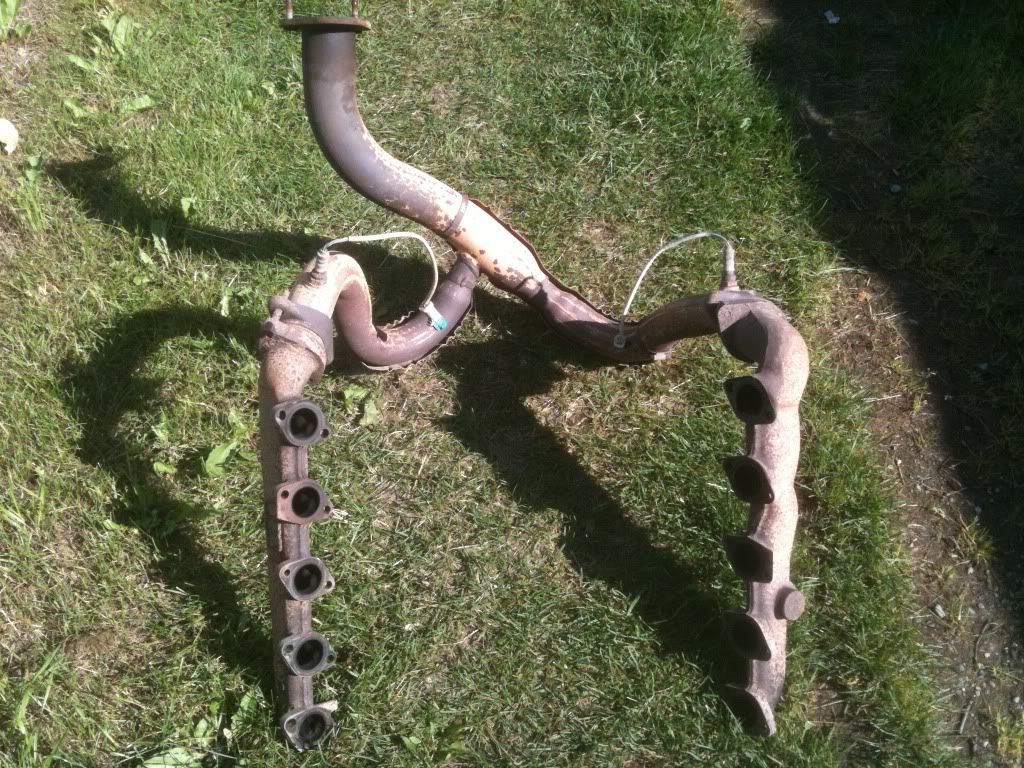
After the manifolds were loose, I separated the flange from the y-pipe to the CAT. Again, the nuts had a lot of rust scale. It seemed like all my wrenches/sockets were either too small, or they were too big. But after working on them for about 20 minutes, and using a good amount of Freeze-Off, I finally got them broke free. Note that two of the CAT flange studs are attached to the y-pipe and one is attached to the CAT. This will have to be removed later to bolt the new y-pipe on. Once the flange was loose, I used the small pry bar to push the manifolds over the broken studs. I thought I could get the manifolds and y-pipe out as a single unit, but the front driveline was in the way. So, I used an 8mm socket and the small ratchet to remove the straps from the front u-joint and dropped the front end of the driveline down and out of the way. Again, it may be easier to work without the driveline hanging in the way, but I was able to work around it. Once I had the driveline down, I was able to carefully work the manifold/y-pipe assembly back and down. The instructions say to remove the starter, but I didn’t need to for the removal. WORKING TIME: about 0.5 hours.
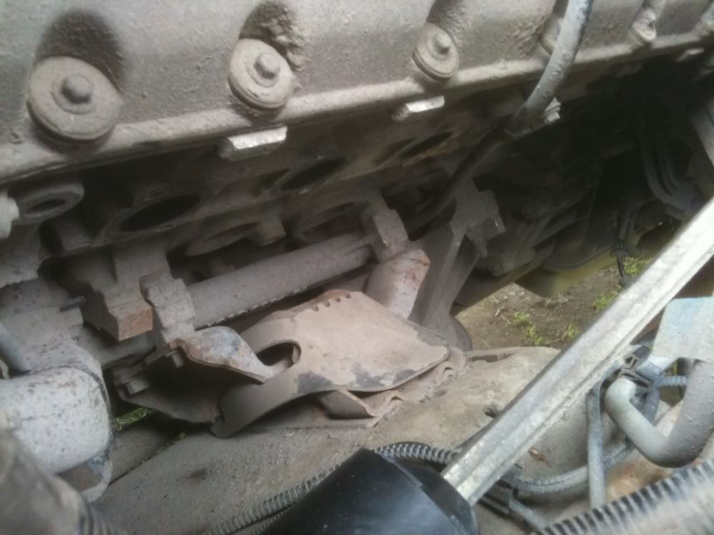
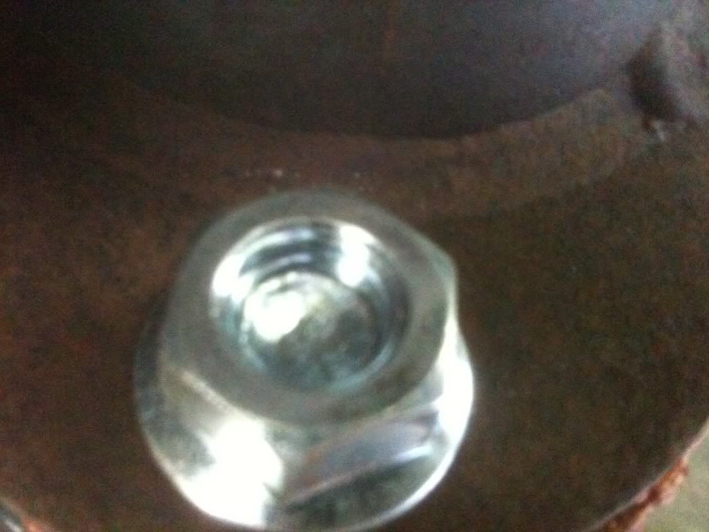
With the manifolds removed, I got to the task of removing the eleven broken studs. I didn’t even bother with vise grips, double nuts, or drills and easy-outs. I went straight to the welder. I threaded new 8x1.25 nuts onto the broken studs, leaving about one thread showing in each of the nuts. Then, I welded the end of the studs onto the nuts. After welding, eight of the studs easily spun right out. The other three took a lot more effort. I tried welding nuts on those last three studs several times, but every time I tried to turn them, the end of the studs would just tear off. I finally found a few small castle nuts in my spare parts collection and, after driving them down onto the studs, was able to weld them on between the castles with enough meat to turn the studs without them breaking. Still, even once I got them broke free, they didn’t just spin out. It took a lot of force to turn them, right up to the end of the threads. Once all the studs were out, I cleaned up the heads with a wire brush. WORKING TIME: about 3.0 hours.
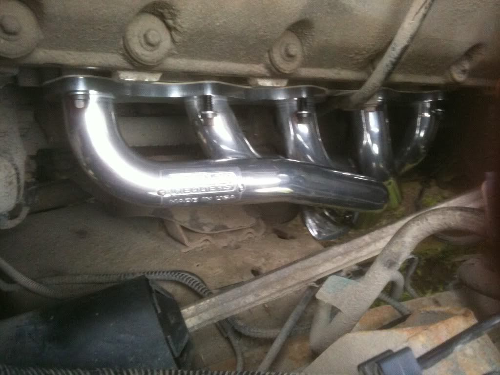
After the heads were cleaned up, I installed the lower header bolts loosely in the heads and slipped the header gaskets on. The left side gasket slipped behind the dipstick tube and into place, even though the instructions said to cut the gasket AND remove the tube. Then, wearing nitrile gloves to keep the oil from my hands off the ceramic coating, I slid the headers up into place from underneath and set them on the lower bolts. There is plenty of room on the left side, but it’s pretty tight on the right. Removing the starter like the instructions say may provide more room, but I didn’t find it necessary. After putting the top bolts in and snugging everything up, I checked clearances. And, although there were some tight spots, everything fit well. There was no need to clearance the frame, or even re-route any hoses or wires. And I didn't even have to remove the dipstick tube like the instructions said to do. At this point, it started raining and I put the tools away for the night. WORKING TIME: about 0.5 hours.
The next afternoon, the rain looked like it was going to quit. I laid a tarp under the truck so I didn’t have to lie on the wet ground and got back to it. (It rained off and on throughout the rest of the install.) Once again, I checked clearances. Satisfied that everything was going to fit, I tightened all the header bolts. Then, I used a hammer to beat the remaining stud out of the CAT flange, cleaned the old gasket off of the CAT flange, gave it a good wire-brushing, and put a bead of Ultra Copper on it. I then put the bolts in the collector flanges, and tried to install the y-pipe, but I couldn’t even get it close to where it was supposed to go. I finally figured out that the tab that’s supposed to bolt up to the tranny was bent, hitting the tranny whenever I got the y-pipe close. So, I used a hammer to gently tap the tab forward. With the tab out of the way, I removed the tranny bolt that the tab mounts to, lifted the y-pipe back into position and threaded the nuts onto the right side collector flange bolts. But, with the right side loosely connected, I couldn’t get the left side to fit. The ball was about a half an inch farther out than the socket. Well, I pushed and pulled, and even gently pried on the headers and y-pipe, but I could never get it closer than about a quarter inch. So, I finally loosened the header bolts just until the washers were loose. Once I did that, the y-pipe slipped easily into place. After loosely bolting the collector and CAT flanges, I re-tightened the header bolts. Then, after rotating the collector flanges so I could get at five of the six bolts with a socket, I used the 1/2-inch impact driver to snug up the flange bolts. I used a pair of wrenches to tighten the last one, and then fully tightened the other five with the impact. WORKING TIME: about 2.5 hours.
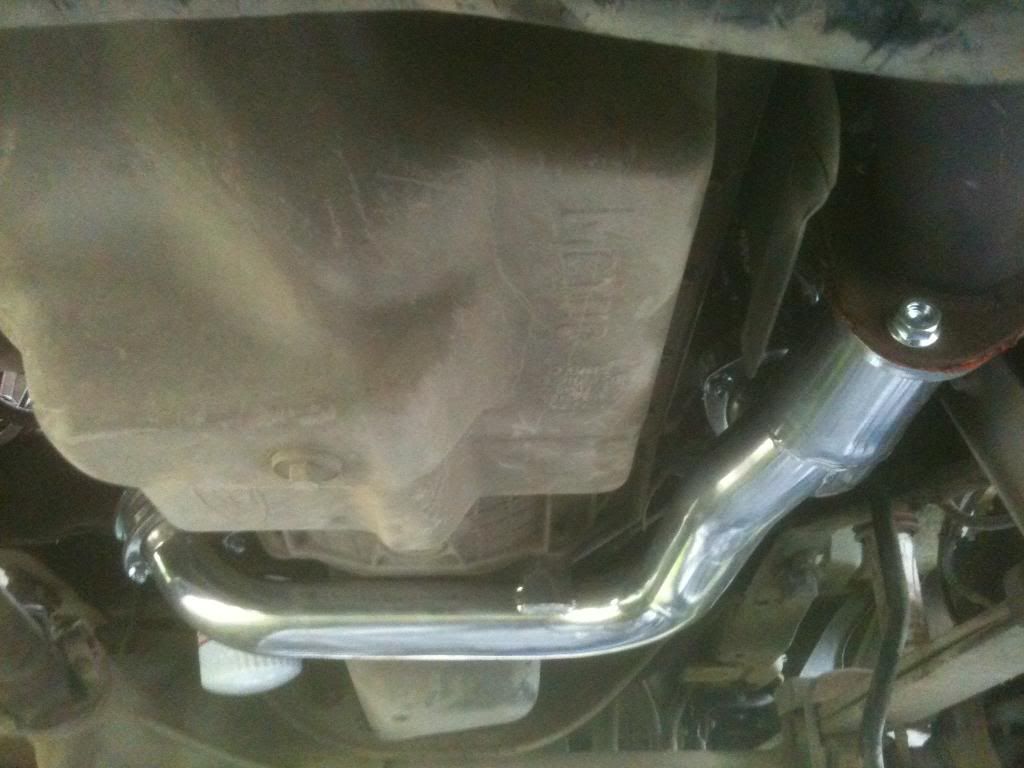
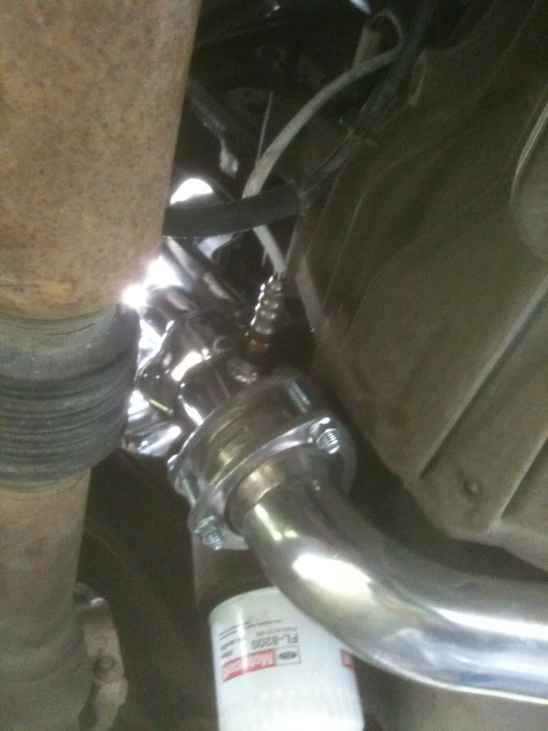
After tightening the collector flange bolts, I tightened the CAT flange bolts as much as I dared. The bolts that came with the headers are at least a quarter inch too short, and only have a couple of threads engaged. So these three bolts will be getting replaced at the first opportunity I have. After the CAT was attached, I had to use the hammer to bend the tranny tab back into place and bolted it on. As you can see from the picture, the tab now makes an “S” shape in order to fit. But, that tab makes the whole setup rock solid. The last thing I did under the truck was install the two new O2 sensors with the special O2 socket and plug them in to the harness. There was plenty of wire on the left side. The right side wire was just barely long enough. I’m going to keep an eye on it to see if it looks like it needs more strain relief. But it shouldn't, since the y-pipe is bolted to the tranny and everything is so solid. So with everything bolted up tight, I pulled all the tools out from under the truck, reinstalled the air filter housing, and hooked up the battery. WORKING TIME: about 1.0 hours.

It took almost nine hours of working time to swap manifolds and y-pipe with a much freer flowing header and y-pipe, with about four of that in sporadic rain. If you don’t consider the time spent removing all the broken studs, the header install took just under six hours. As a comparison, it took me about five hours to do my first header install on the straight-six in my Jeep Wrangler. So, overall, I’m satisfied with the installation. There were definitely some snags, and if I had to do it again, I could probably get it done in about three and a half or four hours (assuming no broken studs). The install itself is pretty straightforward, with the only real wildcard being the stud removal process. If you are prepared for that, have moderate skills and an adequate inventory of hand tools, and set aside a decent block of time, you can do this project.
Here are some things I learned during this install. Hopefully, they'll help you avoid some of the problems I ran into.
Now for the results. I’ve only driven it twice so far, but I can tell you that there is a definite improvement in low end power. With the stock setup, I was never able to spin the tires on dry pavement, and would have to actually try to do it when wet. I always thought that was because I had good tires. But after the header install, it will spin ‘em dry, no problem. And I have to really watch my right foot on wet pavement because it will light ‘em up with even light throttle. It’s actually pretty impressive. I don’t know if it’s the headers, the y-pipe, the new O2 sensors, or a combination of all the new parts. But, this is how the truck should have come from the factory. If you're on the fence about ordering a set of Hedman's, I say go for it. Even with the crappy instructions and a few minor fitment issues, the install isn't too difficult and the improvement is noticeable.
The new headers arrived in a single large box via FedEx. Upon opening it, it seemed that the box was too large, having enough empty space inside that the headers could easily slide around and bang into each other during shipping. But the y-pipe and both headers were each well wrapped in sheet foam. Inside the foam, they were wrapped in heavy plastic bags. And, each of the collector flanges were even wrapped in stretch film to keep them from rattling against the collectors and damaging the ceramic finish. So, even though I was initially concerned, the packaging was sufficient to allow the headers to arrive in good condition. There was also a bag of hardware and a set of manifold gaskets along with a warranty card, Hedman stickers, and installation instructions.
I separated the instructions and began to familiarize myself with the installation process. The first thing I noticed was that the top of the sheet was stamped with the part numbers and application. The part numbers matched what I ordered (along with no.89660, the non-ceramic coated version), but the application was wrong. It listed these part numbers for a Ford 6.8L V-10 2WD (Automatic Only). And, since I have a 4WD, I got a little nervous and had to verify that I had ordered the right part. After a quick web investigation, I decided that I had ordered (and had received) the correct unit, so I soldiered on. Some steps made sense, like disconnecting the battery, removing the air cleaner housing, and disconnecting the O2 sensors. But there were other things in the instructions that didn’t make sense, like references to removing the starter, loosening the motor mounts, raising the engine, removing the dipstick tube, and cutting the left gasket between the last two ports and the front four ports. Needless to say, I was starting to think that this was going to be a much more difficult installation than I had planned on. Still, the headers weren’t going to do me any good sitting on my living room floor, so I just took a deep breath and started gathering the following tools, parts, and supplies:
1/2, 3/8, and 1/4-inch hand ratchets, as well as a 3/8-inch air ratchet, a 1/2-inch impact driver, and various metric and SAE sockets, extensions, and wobbly/universal adapters.
Various metric and SAE wrenches, a small pry bar, a hammer, an O2 sensor socket, a wire brush, a flat screwdriver, and a 110v MIG welder.
Hedman No. 89666 Hedder with Hedman hardware and manifold gaskets.
NGK O2 sensors, nitrile gloves, 8x1.25 nuts, Freeze-Off penetrating spray, and Ultra Copper high temp gasket maker.
I started the project by disconnecting the battery. Then, I disconnected the MAF sensor connector, unclipped the air filter canister and used the screwdriver to separate the canister from the intake tube and set it aside. Then I swung the intake tube out of the way. It might be better to either remove the tube entirely, or tie it off, since it likes to swing back in the way on occasion. I thought about removing the tires and inner fender wells to give me better access to the exhaust, but I decided against it. As it turned out, I was able to get everything done with minimal hassle, but it would probably be easier if they were removed. After getting the airbox out of the way, I unplugged the O2 sensors. Then, I started removing manifold studs. For the most part, a short 13mm wrench was enough to either break the studs loose, or break them off. Some were easier to get to with a small ratchet. One of the stud nuts was 12mm. I’d imagine that they all started as 12mm, but all the rust scale made it necessary to use the 13 for most of them. After the nuts were loose, I spun the studs out with the 3/8-inch air ratchet. When all was said and done, I had eleven broken manifold studs. I’m not even sure how the manifolds stayed on, let alone how they didn’t just leak all the exhaust out into the engine bay. WORKING TIME: about 1.25 hours.
After the manifolds were loose, I separated the flange from the y-pipe to the CAT. Again, the nuts had a lot of rust scale. It seemed like all my wrenches/sockets were either too small, or they were too big. But after working on them for about 20 minutes, and using a good amount of Freeze-Off, I finally got them broke free. Note that two of the CAT flange studs are attached to the y-pipe and one is attached to the CAT. This will have to be removed later to bolt the new y-pipe on. Once the flange was loose, I used the small pry bar to push the manifolds over the broken studs. I thought I could get the manifolds and y-pipe out as a single unit, but the front driveline was in the way. So, I used an 8mm socket and the small ratchet to remove the straps from the front u-joint and dropped the front end of the driveline down and out of the way. Again, it may be easier to work without the driveline hanging in the way, but I was able to work around it. Once I had the driveline down, I was able to carefully work the manifold/y-pipe assembly back and down. The instructions say to remove the starter, but I didn’t need to for the removal. WORKING TIME: about 0.5 hours.
With the manifolds removed, I got to the task of removing the eleven broken studs. I didn’t even bother with vise grips, double nuts, or drills and easy-outs. I went straight to the welder. I threaded new 8x1.25 nuts onto the broken studs, leaving about one thread showing in each of the nuts. Then, I welded the end of the studs onto the nuts. After welding, eight of the studs easily spun right out. The other three took a lot more effort. I tried welding nuts on those last three studs several times, but every time I tried to turn them, the end of the studs would just tear off. I finally found a few small castle nuts in my spare parts collection and, after driving them down onto the studs, was able to weld them on between the castles with enough meat to turn the studs without them breaking. Still, even once I got them broke free, they didn’t just spin out. It took a lot of force to turn them, right up to the end of the threads. Once all the studs were out, I cleaned up the heads with a wire brush. WORKING TIME: about 3.0 hours.
After the heads were cleaned up, I installed the lower header bolts loosely in the heads and slipped the header gaskets on. The left side gasket slipped behind the dipstick tube and into place, even though the instructions said to cut the gasket AND remove the tube. Then, wearing nitrile gloves to keep the oil from my hands off the ceramic coating, I slid the headers up into place from underneath and set them on the lower bolts. There is plenty of room on the left side, but it’s pretty tight on the right. Removing the starter like the instructions say may provide more room, but I didn’t find it necessary. After putting the top bolts in and snugging everything up, I checked clearances. And, although there were some tight spots, everything fit well. There was no need to clearance the frame, or even re-route any hoses or wires. And I didn't even have to remove the dipstick tube like the instructions said to do. At this point, it started raining and I put the tools away for the night. WORKING TIME: about 0.5 hours.
The next afternoon, the rain looked like it was going to quit. I laid a tarp under the truck so I didn’t have to lie on the wet ground and got back to it. (It rained off and on throughout the rest of the install.) Once again, I checked clearances. Satisfied that everything was going to fit, I tightened all the header bolts. Then, I used a hammer to beat the remaining stud out of the CAT flange, cleaned the old gasket off of the CAT flange, gave it a good wire-brushing, and put a bead of Ultra Copper on it. I then put the bolts in the collector flanges, and tried to install the y-pipe, but I couldn’t even get it close to where it was supposed to go. I finally figured out that the tab that’s supposed to bolt up to the tranny was bent, hitting the tranny whenever I got the y-pipe close. So, I used a hammer to gently tap the tab forward. With the tab out of the way, I removed the tranny bolt that the tab mounts to, lifted the y-pipe back into position and threaded the nuts onto the right side collector flange bolts. But, with the right side loosely connected, I couldn’t get the left side to fit. The ball was about a half an inch farther out than the socket. Well, I pushed and pulled, and even gently pried on the headers and y-pipe, but I could never get it closer than about a quarter inch. So, I finally loosened the header bolts just until the washers were loose. Once I did that, the y-pipe slipped easily into place. After loosely bolting the collector and CAT flanges, I re-tightened the header bolts. Then, after rotating the collector flanges so I could get at five of the six bolts with a socket, I used the 1/2-inch impact driver to snug up the flange bolts. I used a pair of wrenches to tighten the last one, and then fully tightened the other five with the impact. WORKING TIME: about 2.5 hours.
After tightening the collector flange bolts, I tightened the CAT flange bolts as much as I dared. The bolts that came with the headers are at least a quarter inch too short, and only have a couple of threads engaged. So these three bolts will be getting replaced at the first opportunity I have. After the CAT was attached, I had to use the hammer to bend the tranny tab back into place and bolted it on. As you can see from the picture, the tab now makes an “S” shape in order to fit. But, that tab makes the whole setup rock solid. The last thing I did under the truck was install the two new O2 sensors with the special O2 socket and plug them in to the harness. There was plenty of wire on the left side. The right side wire was just barely long enough. I’m going to keep an eye on it to see if it looks like it needs more strain relief. But it shouldn't, since the y-pipe is bolted to the tranny and everything is so solid. So with everything bolted up tight, I pulled all the tools out from under the truck, reinstalled the air filter housing, and hooked up the battery. WORKING TIME: about 1.0 hours.
It took almost nine hours of working time to swap manifolds and y-pipe with a much freer flowing header and y-pipe, with about four of that in sporadic rain. If you don’t consider the time spent removing all the broken studs, the header install took just under six hours. As a comparison, it took me about five hours to do my first header install on the straight-six in my Jeep Wrangler. So, overall, I’m satisfied with the installation. There were definitely some snags, and if I had to do it again, I could probably get it done in about three and a half or four hours (assuming no broken studs). The install itself is pretty straightforward, with the only real wildcard being the stud removal process. If you are prepared for that, have moderate skills and an adequate inventory of hand tools, and set aside a decent block of time, you can do this project.
Here are some things I learned during this install. Hopefully, they'll help you avoid some of the problems I ran into.
- The instructions that came with the headers are nearly worthless. If I had followed them, it would have easily added several hours to the project.
- There is no CAT flange gasket in the kit. I tried to buy one after I realized that, but none of the four parts stores here had one (including the local Ford dealer).
- The CAT flange bolts that come with the kit are too short and will need to be replaced.
- Install the lower header bolts as far as you can before setting the header in place. Having an extra half inch of bolt to thread in with the header pipes in the way wastes a lot of time.
- It takes a few different styles of wrenches, wobbly sockets, and extensions to effectively thread the header bolts in quickly.
- It’s fairly easy to tighten the header bolts with only a 5-inch long, 16-point, box end wrench, just don’t expect it to be quick.
- Tightening the right side bolts is pretty easy to do through the right fender well.
- Tightening the left side bolts is very easy to do from the engine bay with the intake out of the way, as long as you have something secure to stand on.
- You need something secure to stand on.
- My welding skills leave a little something to be desired, especially at odd angles with poor visibility in a cramped engine bay.
- Connect the y-pipe to the headers and CAT before tightening the manifold bolts, or expect to do it twice.
- Check the tranny mount tab on the y-pipe for clearance, it may need adjusted.
- Sometimes it rains in Alaska. Wait… I already knew that.
Now for the results. I’ve only driven it twice so far, but I can tell you that there is a definite improvement in low end power. With the stock setup, I was never able to spin the tires on dry pavement, and would have to actually try to do it when wet. I always thought that was because I had good tires. But after the header install, it will spin ‘em dry, no problem. And I have to really watch my right foot on wet pavement because it will light ‘em up with even light throttle. It’s actually pretty impressive. I don’t know if it’s the headers, the y-pipe, the new O2 sensors, or a combination of all the new parts. But, this is how the truck should have come from the factory. If you're on the fence about ordering a set of Hedman's, I say go for it. Even with the crappy instructions and a few minor fitment issues, the install isn't too difficult and the improvement is noticeable.
The following users liked this post:
#2
08-10-2011, 06:25 PM

 )
)
The following users liked this post:
#3
08-10-2011, 06:50 PM
The following users liked this post:
#4
08-10-2011, 06:55 PM
The following users liked this post:
#5
08-10-2011, 08:59 PM
The following users liked this post:
#6
08-10-2011, 10:18 PM

The following users liked this post:
#7
08-10-2011, 11:42 PM
$577 shipped
I had originally found a decent deal on the non-ceramic version (part no. 89660) and ordered them at the end of July from 4wheelparts. They were $425 plus $35 standard shipping to Alaska (free to the lower 48) and I added a 5% coupon I found on line to bring the total down to $439 shipped. But, a few days after I placed the order, they said they wouldn't have any available to ship for a couple of weeks (at least the 18th of August), which meant I wouldn't see them until at least the middle, likely the end of September. (USPS parcel post is sloooooowwwww shipping packages to Alaska.)
So, needing to get this project done before winter, I cancelled that order and found a set of ceramic coated units at Amazon for $577 with free shipping. (Everywhere else I found them wanted more than $600 for the headers plus $125-140 shipping to Alaska.) I ordered them on the 3rd of August and they arrived on the 5th via FedEx. I had them installed on the 7th, a full 11 days before the other set could have even shipped.
So, needing to get this project done before winter, I cancelled that order and found a set of ceramic coated units at Amazon for $577 with free shipping. (Everywhere else I found them wanted more than $600 for the headers plus $125-140 shipping to Alaska.) I ordered them on the 3rd of August and they arrived on the 5th via FedEx. I had them installed on the 7th, a full 11 days before the other set could have even shipped.
The following users liked this post:
Trending Topics
#8
08-11-2011, 11:53 AM

Former Vendor

The following users liked this post:
#9
08-11-2011, 12:33 PM
The following users liked this post:
#10
08-11-2011, 10:46 PM
The following users liked this post:
#11
08-12-2011, 07:20 AM
The following users liked this post:
#12
08-12-2011, 08:08 AM
The following users liked this post:
#13
08-12-2011, 06:01 PM

Postmaster
The following users liked this post:
#14
08-12-2011, 09:14 PM
Thanks for all the positive comments and the rep points guys. After all the good info I've gotten from the folks here at FTE, I'm glad I could give a little something back to the board.
jh818: I don't know what would be different between the trucks and the Ex as far as header fitment goes. JBA lists one part number for both applications, but Gibson lists different part numbers for each. Banks and Doug Thorley only list part numbers for the truck, but I know both have been successfully installed on Ex's. I would imagine that the Hedman's would fit, but I'd give 'em a call to verify. Or, dig around and see if anybody else has done it already.
jh818: I don't know what would be different between the trucks and the Ex as far as header fitment goes. JBA lists one part number for both applications, but Gibson lists different part numbers for each. Banks and Doug Thorley only list part numbers for the truck, but I know both have been successfully installed on Ex's. I would imagine that the Hedman's would fit, but I'd give 'em a call to verify. Or, dig around and see if anybody else has done it already.
The following users liked this post:
#15
08-12-2011, 09:32 PM

Senior User

The following users liked this post: