
Alternator wiring!!!!

Thread Starter
|
Junior User
Joined: Sep 2007
Posts: 50
Likes: 0
From: Victoria West
Alternator wiring!!!!
I've spent an enormous time researching this on Ford-trucks.com and came close, but there is still a few details that eludes my frustration.
I've changed my alternator/regulator to a one-wire alternator, pretty much like the Prestolite alternators. The major problem is the amm meter shows no response and the aftermarket alternator warning lamp doesn't respond either.
I had the alternator checked and all is good. I went through the wiring with a fine haircomb and even cross referenced the circuit with all the diagrams I could find, but still nothing. Hell, I'm not even sure the alternator is charging up at all!
There's current from the battery, but I'm not sure how to check if the dang thing is working or not.
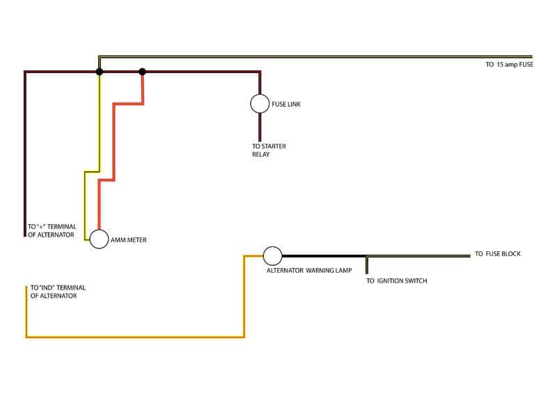
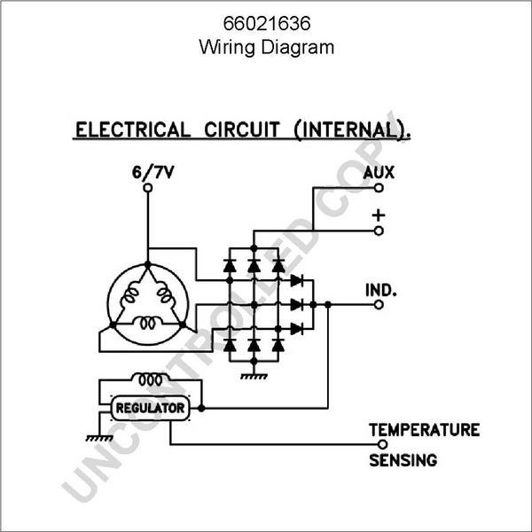
Anyway, I have attached two pictures of the wiring in the vehicle and the circuit for the alternator. Can anyone see where the problem lies?
I've changed my alternator/regulator to a one-wire alternator, pretty much like the Prestolite alternators. The major problem is the amm meter shows no response and the aftermarket alternator warning lamp doesn't respond either.
I had the alternator checked and all is good. I went through the wiring with a fine haircomb and even cross referenced the circuit with all the diagrams I could find, but still nothing. Hell, I'm not even sure the alternator is charging up at all!
There's current from the battery, but I'm not sure how to check if the dang thing is working or not.
Anyway, I have attached two pictures of the wiring in the vehicle and the circuit for the alternator. Can anyone see where the problem lies?
Moderator


Joined: Jan 2001
Posts: 57,005
Likes: 2,750
From: Virginia

On the right side of "alternator warning lamp" in your diagram, why do you have this hooked to a fuse block?
If this "fuse block" connection is hot all the time, the alternator is active all the time and will run the battery down. If it's hot with the key in run only, then it should work, but it would be redundant, since you already have a key-on power source from the keyswitch.
As far as your stock ammeter is concerned, it probably never worked in the first place, most of them rarely do.
Thread Starter
|
Junior User
Joined: Sep 2007
Posts: 50
Likes: 0
From: Victoria West
The black green wire (according to the wiring diagram in the Haynes manual) also splices up to the instrument cluster. I've cross-referenced this with a 68 Mustang diagram and a 81-86 diagram and a Painless wiring diagram.
Any suggestions?
Any suggestions?
Moderator
Joined: Jan 2001
Posts: 57,005
Likes: 2,750
From: Virginia
I don't know what you are working on. All I know is that if you want a dash "GEN" light, the light needs to be in a plastic socket, and one side of the bulb is fed by the keyswitch, and the other side of the bulb feeds the trigger terminal on the alternator to bring it online.
When the keyswitch is turned on, but the engine is not running(or the alternator fails), the trigger terminal of the alternator is near ground, and the light lights up. When the alternator starts charging, the trigger terminal of the alternator raises it's voltage close to 12v. This puts 12v on both sides of the "GEN" light, and the light goes out.
When the keyswitch is turned on, but the engine is not running(or the alternator fails), the trigger terminal of the alternator is near ground, and the light lights up. When the alternator starts charging, the trigger terminal of the alternator raises it's voltage close to 12v. This puts 12v on both sides of the "GEN" light, and the light goes out.
Thread Starter
|
Junior User
Joined: Sep 2007
Posts: 50
Likes: 0
From: Victoria West
Thanks for the advice, Franklin2. The plastic socket part got me thinkin'...
I found the source of my problem...a bad salesmen! Sold me a LED bulb, with an onboard resistor, which for some strange reason only takes current from one direction...I had it wired the wrong way. A quick swap of wires and the light went out straight after the motor kicked in. I let the battery run flat, just enough juice to get the motor started, took a volt reading of 12.65V, after 10 minutes of motor running time...13.01V.
The little things is sometimes the source of huge frustration!
Moderator
Joined: Jan 2001
Posts: 57,005
Likes: 2,750
From: Virginia
Yep, LED stands for "Light Emitting Diode". Any kind of diode only flows current one way, like a electrical "check valve". Regular diodes (look like little round black cylinders in the wiring) are used all the time on modern vehicles, when they want to prevent a voltage source from running up a wire backwards, falsely turning something on.

Thread
Thread Starter
Forum
Replies
Last Post
CharlsChainCharlson
1973 - 1979 F-100 & Larger F-Series Trucks
17
May 18, 2016 06:51 PM
F100Jay
1948 - 1956 F1, F100 & Larger F-Series Trucks
6
Apr 6, 2015 02:51 AM


