


Crossover Exhaust Redesign


Thread Starter
|
Senior User
Joined: Nov 2008
Posts: 220
Likes: 1
From: Southeast MN
From the pictures you found, I agree it does look like there is no room for a wrench but in actual use, there is just enough clearance in the valley for a wrench on original rams horn manifolds. The pictures are taken from the wrong angle to see.
Another thing to note is that the bolt holes are not in line. I can't remember the exact pattern but they are staggered by about 1/16". If you put a straight edge tangent to the top or bottom of the holes, you will see. If you have not accounted for this, it will affect your design to a small degree.
Another thing to note is that the bolt holes are not in line. I can't remember the exact pattern but they are staggered by about 1/16". If you put a straight edge tangent to the top or bottom of the holes, you will see. If you have not accounted for this, it will affect your design to a small degree.
I actually did a lot of dimensioning and stuff of the original manifold and I didn't see anything like that. The hole between the two center cylinders and the slot on the back cylinder is actually smaller than the rest of the holes. I actually had 1/2 inch dowels in all of the large holes and then it was clamped to an angle block and they all seemed to be within a matter of a few thousanths I would say.
This model should be pretty close dimensionally to the original manifold that I have. I would even say that a lot of the features should be within a matter of .02-.03 thousanths of an inch or even better.
Some of the stuff though I did kind of go by feel. Mainly because I am running out of time on this project. I only have about 2 1/2 weeks until it should be for the most part done. But then I have about a month until I have to present it to the class. My teacher wants us to focus on the presentation for that last month. Though it doesn't mean though that I can't work on it some more.
But I was going to make a grey iron casting pattern model, 3D print some parts, figure out costs and materials, production, ect. ect. Lots of stuff to do yet so I do need to move forward I could come back to some things though.

Cargo Master


Joined: Apr 2003
Posts: 2,389
Likes: 58
Well it looks like the presentation will be good. However, if you do coonsider production, it will be worthwhile to determine the exact location of all of the holes. That way you can make the best use of the space available for the ports.
Here is a 2d drawing I made of a felpro exhaust gasket. You can see the offset I speak of. I can even send the cad file for it. I drew a line between the centers of the end holes to make it easier to see the offset. I have also verified this by comparing it with a head.
In my drawing, it's .089" offset which is just under 3/32.
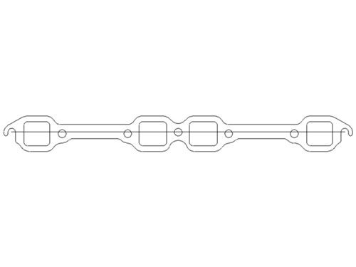
Here is a 2d drawing I made of a felpro exhaust gasket. You can see the offset I speak of. I can even send the cad file for it. I drew a line between the centers of the end holes to make it easier to see the offset. I have also verified this by comparing it with a head.
In my drawing, it's .089" offset which is just under 3/32.

Thread
Thread Starter
Forum
Replies
Last Post
mytoolman
1948 - 1956 F1, F100 & Larger F-Series Trucks
5
Dec 15, 2016 01:05 PM
jumbo190
Ford Truck Parts for Sale
0
Dec 29, 2015 10:05 AM
Bullitt233
1987 - 1996 F150 & Larger F-Series Trucks
5
Dec 11, 2015 09:05 AM
dirtydeeds
1973 - 1979 F-100 & Larger F-Series Trucks
289
Apr 26, 2013 02:01 PM





