Circuit Breakers-Orginal 55 f-100
#1
 09-08-2009, 01:35 PM


Join Date: May 2006
Posts: 21
Likes: 0
Received 0 Likes
on
0 Posts
Circuit Breakers-Orginal 55 f-100
Been a long time since I've been on the boards! I'm finally installing my new wiring harness and got some questions that I can't find answers. I've gone back to a 6 volt system and the wiring harness diagram does not show any wires going to the original circuit breakers (those little oblong metal boxes that are attached to the speedometer housing). I've been told by some folks that they are only needed if you have a 12 volt system because the gauges were still 6 volt. The original ones have a bunch of wires coming off from them (but I took it off 15 years ago when I started restoration) and the wires all look a uniform yellow in color. Can anyone clue me in pls! And does anyone have pictures of original wiring installations just so I can see where stuff gets run. Next question is about fusing. I bought a new 6 volt headlight switch and was told there is a circuit breaker internal to the switch that just opens the circuit if it gets hot. If that is correct should I consider another fuse to be on the safe side and where should i put it so as to not spoil my "stock" look. Just spent a lot of money having Scott Speedometer rebuild my speedo and all gauges and new fuel sending unit and don't want to toast anything with my electical incompetence. After 15 yrs of work I'm gettin close, so will post some pics later this week. tks in advance. Steve
#2
09-08-2009, 01:38 PM

Fleet Owner
#3
09-08-2009, 10:48 PM

Post Fiend
Ok I'm probably going to cause a little bit of a debate about signal flow with this post, because you have a 55 but what I'm going to post will work just fine even for your 55. the 51/52 also had circuit breakers on the speedometer and the wiring was little changed until 56 and the introduction of 12 volt negative ground systems.
The Circuit breaker in your headlight switch is to protect it in case of a lighting short. Some folks say the 55 had th egenerator or ignition power going directly up to the headlight switch, and that may be tru, but youwill have double protection for your lighting circuits with it wired like the diagram below. If you have a 55 shop manual, there will be a wiring diagram in the pack by the way.
Here is a solid wiring scheme for trucks with circuit breakers it is the 51/52 wiring off the CBs:
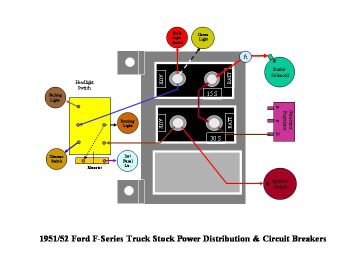
If it's too hard to read, there is a copy of it in my #4 gallery about electrical rewiring. If that one doesn't work, send me a PM with your real e-mail addres and I'll send you a copy of the Power Point Original.
Your gauge power will come off the "ACC" post onthe ignition switch. The gauges should be joined together on the power side by a metal strap. The other post on each gauge goes out to the sending units...Amp gauge is the very light blue circle (withthe "A" in it) on the circuit breaker to the Starter Solenoid in the diagram above. It has an induction loop on the back that the wire runs through.
The Circuit breaker in your headlight switch is to protect it in case of a lighting short. Some folks say the 55 had th egenerator or ignition power going directly up to the headlight switch, and that may be tru, but youwill have double protection for your lighting circuits with it wired like the diagram below. If you have a 55 shop manual, there will be a wiring diagram in the pack by the way.
Here is a solid wiring scheme for trucks with circuit breakers it is the 51/52 wiring off the CBs:
If it's too hard to read, there is a copy of it in my #4 gallery about electrical rewiring. If that one doesn't work, send me a PM with your real e-mail addres and I'll send you a copy of the Power Point Original.
Your gauge power will come off the "ACC" post onthe ignition switch. The gauges should be joined together on the power side by a metal strap. The other post on each gauge goes out to the sending units...Amp gauge is the very light blue circle (withthe "A" in it) on the circuit breaker to the Starter Solenoid in the diagram above. It has an induction loop on the back that the wire runs through.
The following users liked this post:
#4
09-09-2009, 12:06 AM
The '55 had circuit breakers built into the headlight switch. Only the 53/4, and the earlier ones had the two oblong circuit breakers. If yours had those, then the speedo was transplanted, or they were added for some extra circuit. If you're going with a stock wiring job, Julie has a copy of the 55 diagram, which is visually the same as the 56, except for signal flow, and wire sizes. As to the circuit breakers with wiring remnants, all the hot all the time wires joined at those circuit breakers. There was a little brass strip that joined the two together, and attached to the "in" of the first breaker, with the wire going to the solenoid. For the '55, all the hot wires join at the "Bat" post of the headlight switch. The '55 shouldn't have anything added to the back of it in the way of external breakers if it's "concours" correct.
#5
09-09-2009, 02:35 PM
Join Date: May 2006
Posts: 21
Likes: 0
Received 0 Likes
on
0 Posts
Tks for the info to all. My major question has been answered that 55's don't have them as stock. Julie tks for the drawing and yup i do have a 54/55 book and schematic. But,,,,, you over estimate my abilities to follow the one in the book. I need the kind that say "put the red and blue wire on the positive post of ......." . Lol. Anyway I really appreciate your help and will be asking more questions about wiring as I jump back into the job tommorrow. By the way I do have a 53/54 headlight switch and my old 55 switch and one of the differences is the 55 has a metal button underneath that seems to be a reset button, maybe?
#6
09-09-2009, 07:48 PM
The 53/4 should be more like the 48-52 style, assuming the 48-52 are the same. The metal button is not a reset button, it is the ****, and shaft release button. There should be one major difference. The 55 should be big and black, and have a fuse holder on the back. The 53/4 should be smaller, and metal, except for the top, and should have 4 or 5 tabs sticking up from the main body. There should be two "B" terminals on the 53/4, as well as a "P", "R", and something else, that I can't remember right now.
#7
09-09-2009, 09:04 PM
Post Fiend
Tks for the info to all. My major question has been answered that 55's don't have them as stock. Julie tks for the drawing and yup i do have a 54/55 book and schematic. But,,,,, you over estimate my abilities to follow the one in the book. I need the kind that say "put the red and blue wire on the positive post of ......." . Lol. Anyway I really appreciate your help and will be asking more questions about wiring as I jump back into the job tommorrow. By the way I do have a 53/54 headlight switch and my old 55 switch and one of the differences is the 55 has a metal button underneath that seems to be a reset button, maybe?
The 53/4 should be more like the 48-52 style, assuming the 48-52 are the same. The metal button is not a reset button, it is the ****, and shaft release button. There should be one major difference. The 55 should be big and black, and have a fuse holder on the back. The 53/4 should be smaller, and metal, except for the top, and should have 4 or 5 tabs sticking up from the main body. There should be two "B" terminals on the 53/4, as well as a "P", "R", and something else, that I can't remember right now.
Here are diagrams for the 51-54 switch (marked 51/52) and th e56 light switch with the fuse on the back.....please disregard the other things that are on the same page of my diagrams.
It's interesting that yougot a 6 volt light switch with a circuit breaker in it. I didn't think they were available. That circuit breaker and th einstrument light dimmer are th eonly things that make the difference when using 6 volt or 12 volt.
The boxes marked "Hot Bus" are the power inputs from the Circuit Breakers as in the first drawing I posted.
Trending Topics
#8
09-09-2009, 09:39 PM
Yep exactly WJ! The 55 is alot like the 56 switch, and the 51 up to 54 are the same. 48-50 did not have the instrument light hard tab or rheostat (had a separate switch) which on the later switches was shunted from the power input for the running lights (your missing letter "H" which goes down to the high beam switch then out to the headlights).
It's interesting that yougot a 6 volt light switch with a circuit breaker in it. I didn't think they were available. That circuit breaker and th einstrument light dimmer are th eonly things that make the difference when using 6 volt or 12 volt.
#9
09-10-2009, 07:21 PM
Join Date: May 2006
Posts: 21
Likes: 0
Received 0 Likes
on
0 Posts
OK, so today I got everything hooked up to the front lights. In the wiring diagram it says the main loom wires for front lights go into the "front junction block". The ends of wires from main loom and all the front lights are all male ends. So I started looking for a junction block. From the part numbers it appears that it is same on cars and trucks. Found one on ebay! It is a bakelite box with 8 holes on each side. That sound right to you folks? Next issue I found is the body to motor ground strap. From my parts box I found a beautiful flat looking braided copper wire(after I bead blasted it) one but the wiring harness came with a much smaller gauge wire. I had left the original one in place and it looks to be a bare copper wire one. Which should I use? Goes from firewall to behind the distributor on motor. Next question: Is the blinker switch inside the steering column same for car as truck. I have an old aftermarket one but would like to use real thing. Any ideas where to find NOS or slightly used one? Tks again for the help.
#10
09-11-2009, 03:03 AM
Post Fiend
OK, so today I got everything hooked up to the front lights. In the wiring diagram it says the main loom wires for front lights go into the "front junction block". The ends of wires from main loom and all the front lights are all male ends. So I started looking for a junction block. From the part numbers it appears that it is same on cars and trucks. Found one on ebay! It is a bakelite box with 8 holes on each side. That sound right to you folks? Next issue I found is the body to motor ground strap. From my parts box I found a beautiful flat looking braided copper wire(after I bead blasted it) one but the wiring harness came with a much smaller gauge wire. I had left the original one in place and it looks to be a bare copper wire one. Which should I use? Goes from firewall to behind the distributor on motor. Next question: Is the blinker switch inside the steering column same for car as truck. I have an old aftermarket one but would like to use real thing. Any ideas where to find NOS or slightly used one? Tks again for the help.
Use the older heavier gronding strap. your 6 volt wiring requires larger wires because at teh lower voltage the same wattage (demand from the part) requires more amps! Bigger Grounding strap and bigger wires.
Which brings me to a question: you aren't trying to adapt a 12 volt EZ wire harness for 6 volt use are you? I fyou are, th ewires will not be near large enough. Be sure youyr harness is rated for 6 volts - very improtant

Last question, switches are the same mechanically, but wire colors may be different.
LMCsells a column mounted signal switch for your truck as I'm sure Dennis Carpenter and C&G will as well - about $70-$85.
Here is the link to LMCs page:
http://www.lmctruck.com/icatalog/fa/full.aspx?Page=77
PS Get a new one not used.

Thread
Thread Starter
Forum
Replies
Last Post
1964FORDTUF
1961 - 1966 F-100 & Larger F-Series Trucks
5
10-09-2016 11:02 AM
jvmcc
1948 - 1956 F1, F100 & Larger F-Series Trucks
12
07-22-2016 02:04 AM
jvmcc
1948 - 1956 F1, F100 & Larger F-Series Trucks
2
06-10-2016 04:20 PM