ALERT! Full Front Tilt Lineal Actuator Failure/Damage/Solution
#1
 08-31-2009, 05:12 PM


ALERT! Full Front Tilt Lineal Actuator Failure/Damage/Solution
Hi Guys,
Well as many of you know, I have a full front tilt on my 51 F1. I have a point paper that I wrote on it and have sent it out to many of you who are interested in going that way.
Recently, I experienced a catastrophic failure of the lineal actuator that lifts and hold the hood and I thought I'd best get on the horn and get the word out on this before someone else's truck gets dmamged or someone gets hurt.
Background: I was at one of our local vintage car/truck "evenings" sponsored by the outlying cities here in the San Diego area. This was the first year I had participated where the truck was all primered in one color and th echrome had been reinstalled. I had made prior arrangements with th ecoordinatorsz to park the truck in one of the first spots right in front of two resteraunts with side walk dining. I was really excited about showing off the previous years work.
I pulled into the parking spot and the resteaunts were packed. All eyes were apon me! I shut the truck down, flipped up the spotlights, pushed the hood control toggle to the up position and flipped the key to the ignition to the "Start" position (I use the ignition switch start because I have a starter button and it requires the key to open the hood).
As the hood started up I could hear the oooohs and ahhhs of the folks in the sidewalk dining areas as th ehood went up to expose a full mornings polishing on the engine chrome and engie compartment. I sat there with a smug and cocky smile on my face - as proud as could be.
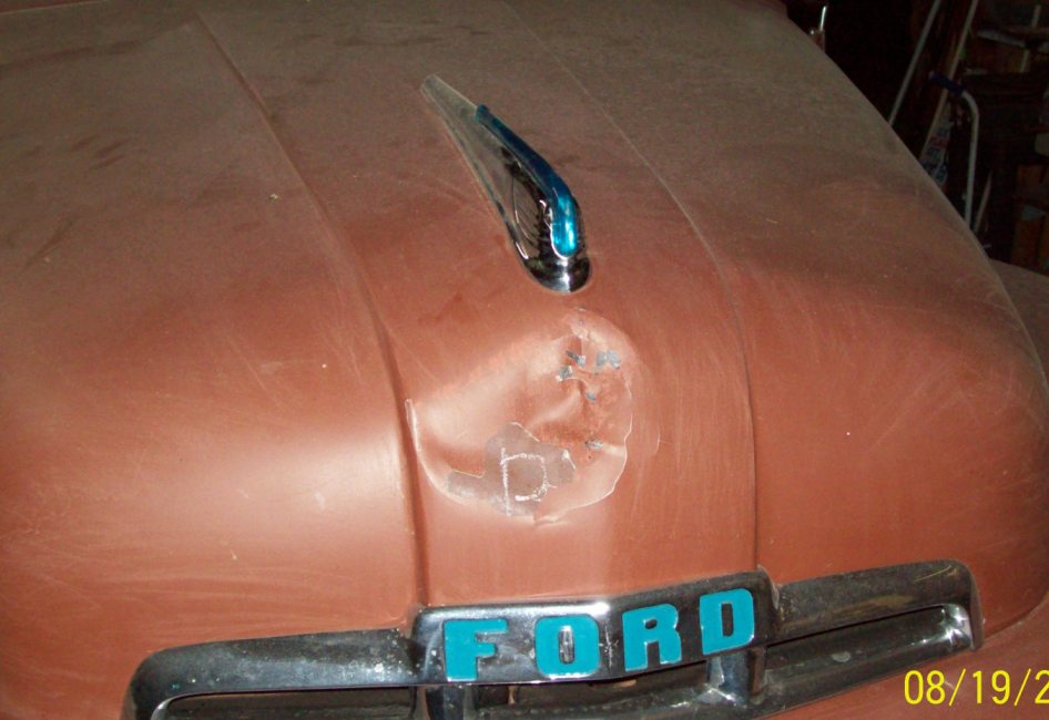
All of a sudden, there was a disconcerting "SNAP" and the entire hood assembly, fenders and all fell away from the front of the truck at a "high rate of speed" and smashed on the high curb I was parked at. The hinge assemblies held and the hood stayed on the truck.
Talk about embarressed!!!!!!! My initial reaction was: What the "H" happened" but quickly changed to "thank God someone wasn't standing there." I felt like a complete fool in front of all those people lifting the hood back into position and trying to get it closed.
The original set up: The truck has an all original sheet metal front clip with no inner fenders. It is bolted together and carried by an "H" type framework that is hinged to the frame rails forward of the radiator supports. It is lifted by a Firgelli Automations 400 Pound rated 12 inch 12 volt electric lineal actuator model # FA-400-L-12-12"....In my opinion an excellent product which I still highly recommend. Front clip total weight is about 50 pounds. The measured lever arm weight force at the brackets is 123 pounds (what the lift actually pushes and pulls due to position and angles). Lifting and lowering the hood is controlled from the cab by a three position (on-off-on) toggle switch and p[ower applied through the "start" position of the ignition switch-as previously described.

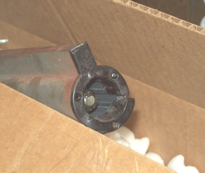
What happened?: Like every piece of equipment, this one has an "Achillese Heel." While the hood was going forward and changed in angle so it had to be held back (to keep it from falling forward) by the lift instead of being pushed up, one of the "cheezy" screws holding the plastic tube cap on the base tube, stripped and was pulled out of it's position, the plastic cap then tore allowing the inner shaft stops past it and to separate from the actuator worm gear in the base tube.
There was a 1/4 inch steel safety cable perminently looped through the (reinforced) radiator support ends and clamped, which runs through a double looped spring on the hood bracket.

Amazingly, while it took me over an hour to get the safety cable end through the center of the spring and aropund the end of the anchor. It had, on it's own, vibrated it's way back into the spring center up past the anchor and detatched itself. Thus when the hood fell forward, it simply slipped out of the spring center un attached.
The results:
Talk about PO'd
I called Firgelli the next day and spoke to their engineers (and for those of you who know me there doesn't have to be much imagination used to determine the tone of that conversation).
Here is what I learned.
While designed to LIFT (push) 400 pounds, the actuators are not designed to PULL 400 pounds or even 200. That's nice to know now, huh?
You can see in the pictures above, the retaining ring failure.
The Fix: In order to fix the problem, the two week design items had to be fixed. The screws needed to b elonger, and the retainer needed to be stronger.
I purchased some #4 x 3/4" Stainless Steel Sheet Metal Screws to replace the 1/4 in long ones. The screws anchor in between the smaller gaps between the ribs in the actuator base tube.


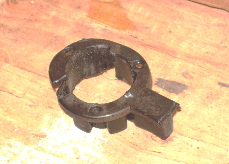
Also, I bought a 3/4 inch brass washer to modify as a retainer.
I enlarged the brass washer inside hole to fit over the actuator shaft and drilled holes to match the position of the plastic cap.


I removed the original screws and installed the brass retainer over the plastic cap inserted teh 1" screws through the brass retainer and plastic cap, coated with "Red Loc-tite," and tightened them down.


As a test, I also repaired the broken actuator with the same arrangement. When I was done, I chained the bottom of the actuator to my garage trusses, and the other end to the back bumper of my truck. I ran the actuator through about 20-25 ful cycles using the actuator to lift the rear end of the truck off the ground each time - so much for ratings. There was no sign of failure or separation of the actuator after testing. I then packaged it back up and returned it to Firgelli.
For those of you who are using Electric Lineal Actuators to raise and lower you hoods or front tilts, I would recommend you check to see if the lifts are being subjected to pulling in the later stages of actuation and if so, adopt some type of preventive strengthening like this.
If you have any questions, please feel free to ask!
Well as many of you know, I have a full front tilt on my 51 F1. I have a point paper that I wrote on it and have sent it out to many of you who are interested in going that way.
Recently, I experienced a catastrophic failure of the lineal actuator that lifts and hold the hood and I thought I'd best get on the horn and get the word out on this before someone else's truck gets dmamged or someone gets hurt.
Background: I was at one of our local vintage car/truck "evenings" sponsored by the outlying cities here in the San Diego area. This was the first year I had participated where the truck was all primered in one color and th echrome had been reinstalled. I had made prior arrangements with th ecoordinatorsz to park the truck in one of the first spots right in front of two resteraunts with side walk dining. I was really excited about showing off the previous years work.
I pulled into the parking spot and the resteaunts were packed. All eyes were apon me! I shut the truck down, flipped up the spotlights, pushed the hood control toggle to the up position and flipped the key to the ignition to the "Start" position (I use the ignition switch start because I have a starter button and it requires the key to open the hood).
As the hood started up I could hear the oooohs and ahhhs of the folks in the sidewalk dining areas as th ehood went up to expose a full mornings polishing on the engine chrome and engie compartment. I sat there with a smug and cocky smile on my face - as proud as could be.
All of a sudden, there was a disconcerting "SNAP" and the entire hood assembly, fenders and all fell away from the front of the truck at a "high rate of speed" and smashed on the high curb I was parked at. The hinge assemblies held and the hood stayed on the truck.
Talk about embarressed!!!!!!! My initial reaction was: What the "H" happened" but quickly changed to "thank God someone wasn't standing there." I felt like a complete fool in front of all those people lifting the hood back into position and trying to get it closed.
The original set up: The truck has an all original sheet metal front clip with no inner fenders. It is bolted together and carried by an "H" type framework that is hinged to the frame rails forward of the radiator supports. It is lifted by a Firgelli Automations 400 Pound rated 12 inch 12 volt electric lineal actuator model # FA-400-L-12-12"....In my opinion an excellent product which I still highly recommend. Front clip total weight is about 50 pounds. The measured lever arm weight force at the brackets is 123 pounds (what the lift actually pushes and pulls due to position and angles). Lifting and lowering the hood is controlled from the cab by a three position (on-off-on) toggle switch and p[ower applied through the "start" position of the ignition switch-as previously described.
What happened?: Like every piece of equipment, this one has an "Achillese Heel." While the hood was going forward and changed in angle so it had to be held back (to keep it from falling forward) by the lift instead of being pushed up, one of the "cheezy" screws holding the plastic tube cap on the base tube, stripped and was pulled out of it's position, the plastic cap then tore allowing the inner shaft stops past it and to separate from the actuator worm gear in the base tube.
There was a 1/4 inch steel safety cable perminently looped through the (reinforced) radiator support ends and clamped, which runs through a double looped spring on the hood bracket.
Amazingly, while it took me over an hour to get the safety cable end through the center of the spring and aropund the end of the anchor. It had, on it's own, vibrated it's way back into the spring center up past the anchor and detatched itself. Thus when the hood fell forward, it simply slipped out of the spring center un attached.
The results:
Talk about PO'd
I called Firgelli the next day and spoke to their engineers (and for those of you who know me there doesn't have to be much imagination used to determine the tone of that conversation).
Here is what I learned.
While designed to LIFT (push) 400 pounds, the actuators are not designed to PULL 400 pounds or even 200. That's nice to know now, huh?
You can see in the pictures above, the retaining ring failure.
The Fix: In order to fix the problem, the two week design items had to be fixed. The screws needed to b elonger, and the retainer needed to be stronger.
I purchased some #4 x 3/4" Stainless Steel Sheet Metal Screws to replace the 1/4 in long ones. The screws anchor in between the smaller gaps between the ribs in the actuator base tube.
Also, I bought a 3/4 inch brass washer to modify as a retainer.
I enlarged the brass washer inside hole to fit over the actuator shaft and drilled holes to match the position of the plastic cap.
I removed the original screws and installed the brass retainer over the plastic cap inserted teh 1" screws through the brass retainer and plastic cap, coated with "Red Loc-tite," and tightened them down.
As a test, I also repaired the broken actuator with the same arrangement. When I was done, I chained the bottom of the actuator to my garage trusses, and the other end to the back bumper of my truck. I ran the actuator through about 20-25 ful cycles using the actuator to lift the rear end of the truck off the ground each time - so much for ratings. There was no sign of failure or separation of the actuator after testing. I then packaged it back up and returned it to Firgelli.
For those of you who are using Electric Lineal Actuators to raise and lower you hoods or front tilts, I would recommend you check to see if the lifts are being subjected to pulling in the later stages of actuation and if so, adopt some type of preventive strengthening like this.
If you have any questions, please feel free to ask!
#2
08-31-2009, 05:35 PM

But there had to be a third factor you didn't mention. the center movement shaft came off the end of the threaded drive shaft. (ie, the travel was too long).
you didn't show us any of the pics inside the central shaft, but it should be threaded as well, right?
SO, in this total case, there wasn't a positive stop on the travel of the central shaft, causing a disconnect of the two, and the retaining cap was not strong enough to hold the weight being applied to the now loose central shaft (in a pulling configuration)..
Or, the plastic cap is supposed to BE the travel stop, which might be ok for a push configuration.
So, maybe you corrected the weak safety stop, BUT you didn't stop the travel before disconnect...and are relying on the 3 screws to hold your new safety stop in place.
my assumption is the central shaft has some pin for the stop condition. I would find a collar (pipe) that would go around the central shaft, like the opening in the washer, and 1/2in long,
spot weld it to the washer as the new stop distance, retaining 1/2 in of threaded contact. (I don't know if there is enough room for another collar inside the housing tho)..
alternatively, you could move the bottom stop on the central shaft up that 1/2 in. (don't know how it is attached).
Sam
#3
08-31-2009, 06:53 PM

Join Date: Jul 1997
Location: Beautiful Hueytown Alabam
Posts: 5,668
Received 727 Likes
on
259 Posts
thanks for the nice detailed writeup Julie... good information.
My flip is fiberglass and much lighter than your sheet metal doghouse... my actuators are rated at 1000 #s lift... (and I don't know that the pull rating actually is either)
Your repair seems sound enough if your trust the extrusions that the sheet metal screws screw into ??? I wonder if (with much more fabrication work ) the washer had tabs in two or three places that slid down OUTSIDE the housing and screws held it on threaded into tapped/threaded holes...say, three of them 120� apart ??? But I guess since you used your actuator as a truck lift things should be ok... on that part... I agree with Sam on the problem of the shaft coming completely out of the actuator when the threads ran out... does your actuator have any type of limit switch that will prevent the screw from 'unscrewing' completely even if you don't have a cap failure ??? just curious.
Mine will run completely to the end and then just 'click' telling me it's at end of travel...same when retracting... I'm assuming there is some kind of slip clutch hickey thing that is doing that... My actuator was actually a lid lifter from a computer mainframe plotter (think lifting the glass top off a coffin sized box with two of these) So..... the internals might be completely different...
I think I'm safe lifting my glass house.... but the information will surely help some other folks.... be sure and keep us posted on what the mfg. has to say and if they will cover the damage (HA-HA)
later
John
My flip is fiberglass and much lighter than your sheet metal doghouse... my actuators are rated at 1000 #s lift... (and I don't know that the pull rating actually is either)
Your repair seems sound enough if your trust the extrusions that the sheet metal screws screw into ??? I wonder if (with much more fabrication work ) the washer had tabs in two or three places that slid down OUTSIDE the housing and screws held it on threaded into tapped/threaded holes...say, three of them 120� apart ??? But I guess since you used your actuator as a truck lift
things should be ok... on that part... I agree with Sam on the problem of the shaft coming completely out of the actuator when the threads ran out... does your actuator have any type of limit switch that will prevent the screw from 'unscrewing' completely even if you don't have a cap failure ??? just curious.Mine will run completely to the end and then just 'click' telling me it's at end of travel...same when retracting... I'm assuming there is some kind of slip clutch hickey thing that is doing that... My actuator was actually a lid lifter from a computer mainframe plotter (think lifting the glass top off a coffin sized box with two of these) So..... the internals might be completely different...
I think I'm safe lifting my glass house.... but the information will surely help some other folks.... be sure and keep us posted on what the mfg. has to say and if they will cover the damage (HA-HA)
later
John
#5
08-31-2009, 08:07 PM
tilt hood mishap
Hey Julie
Sorry that you had this bad experience with your tilt. I appreciate all the work you've done in sharing your original designs/data etc and you're now improving on them.
I've got a tilt on my 58 F100. And I like it Ok, but you know I too have had a mishap. Not as public as yours fortunately for me. But still sheet metal damage etc, and I've got a simple set of hinges on the frame horns and just a pair of cables on each side to limit how far it opens. All human powered and very simple, but I had it set too vertical when opened and one day it just totally went over. I don't know if the cables--those steel cables wrapped in clear vinyl that are common-pretty heavy ones too just stretched beyond how I had them originally or what. But somehow it flipped over forward and crashed on its nose. 'With similar damage to how yours looks.
I fixed everything and that was maybe 2years ago during the build and since i've never had a problem, but I did add a kind of "pin" that I push through the frame horn and hinge assembly simultaneously to prevent any movement while the tilt is in the open/upright position, and of course I lessened the amount of vertical from what I was originally using.
I like what I've got and it works well for me so far, but I think the botom line is to be cautious with front tilts--they are a little risky, no more than than the risk each time I drive down the road--but still a risk.
Wish your truck a speedy recovery.
Tomget
#6
08-31-2009, 08:39 PM
Jules,
Wow, major bummer. Not only did you poke your nose but you had to go and do it in front of a large crowd....that sucks. Like you said, at least no one was standing out there. Another bright note....at least it didn't go smashing the cool blue lens of your hood ornament into the concrete.
Good luck with the repairs
Bobby
#7
08-31-2009, 08:50 PM
Join Date: Jul 1997
Location: Beautiful Hueytown Alabam
Posts: 5,668
Received 727 Likes
on
259 Posts
althought when you think of it Bob... if someone HAD been there it would have softened the impact and saved the hood... the paramedics could have fixed the victim much quicker than Julie will fix the hood....

later
John
Trending Topics
#8
08-31-2009, 08:52 PM
Elder User
Join Date: Nov 2008
Location: Gunbarrel, Co.
Posts: 915
Likes: 0
Received 0 Likes
on
0 Posts
Julie, what a bummer. As good as your pictures are it's still hard to see the detail of the break point on the threaded rod. IMO there was a heat-treat failure or processing thru manufacturing. Looking at the the threads on the end of the acuator they are only there to keep the guide in place. Good luck on your fix. Marty
#9
08-31-2009, 09:21 PM
But there had to be a third factor you didn't mention. the center movement shaft came off the end of the threaded drive shaft. (ie, the travel was too long). Well I though that was the general point I made but maybe it was ambiguous.
you didn't show us any of the pics inside the central shaft, but it should be threaded as well, right? Yes it is, the actuator has a motor with a trnasmission, the screw gear inside the lower half of the actuator shaft turns inside the threaded upper shaft extending it. There is a **** on the bottom of the upper half that tops out at a certain "limit" point, that stop is sensed by the actuator, and the motor stops
SO, in this total case, there wasn't a positive stop on the travel of the central shaft, causing a disconnect of the two, and the retaining cap was not strong enough to hold the weight being applied to the now loose central shaft (in a pulling configuration).. That's absolutely correct but the question really is "why was there no stop on the travel of the central shaft?" Was it because there was a separate stop that failed, or was it because the cap was the stop and that (or either for that matter) were not designed - strength wise - for pulling force only pushing. That's a good question. But honestly it doesn't matter if the stop- irregardless of the configuration, is experiencing 200 pounds of push or pull, it's 200 pounds of pressure on the stop in the same direction whether the lift is pushing 200 pound worth or the hood is pulling 200 pounds worth. And the stops should have handled it.
Or, the plastic cap is supposed to BE the travel stop, which might be ok for a push configuration.
So, maybe you corrected the weak safety stop, BUT you didn't stop the travel before disconnect...and are relying on the 3 screws to hold your new safety stop in place. True - kind of. If the stop stays in place the sensor shuts off the screw gear before it can unscrew. Yes, the new fix is held in by 3 screws (300% longer and stronger material). So it duplicates the original design, just sufficiently stronger. If the cap is not allowed to dislocate, iow if there is a limiting hard stop there, and if there is a stop in the spline that fails again, the base **** of the center shaft will contact the reinforced retainer prior to unscrewing from the gear and be stopped by the pressure sensor. Withthe metal Vs plastic cap and 300% longer screws, the cap/retainer is now strong enough to resist breakthrough. The screw gear will hold the weight after it stops, which is what is supposed to hold the weight not the cap. The cap simply provides resistance for the sensor. In this case there was no resistance because the cap had failed and the gear just kept going until it unscrewed - as you mentioned. So basically, I've reingforced the cap to be a greatly strengthened stop for the actuator (either primary or secondary).
my assumption is the central shaft has some pin for the stop condition. I would find a collar (pipe) that would go around the central shaft, like the opening in the washer, and 1/2in long,
spot weld it to the washer as the new stop distance, retaining 1/2 in of threaded contact. (I don't know if there is enough room for another collar inside the housing tho)..
alternatively, you could move the bottom stop on the central shaft up that 1/2 in. (don't know how it is attached).
Sam
The motion of the actuator is stopped by a pressure/movement sensor that has to have some type of a shut off delay to it. In other words, it has to sense the torque on the shaft for a second or so in order to prevent the initial load from always turning it off. Once I left a wrench on the frame rail between the hinges, and the actuator stopped when it felt the pressure - before reaching the designated limit.
In this particular case, I believe that if there was a stop on the center screw, that traveled up the spline on the top, it either broke off or fell out. I didn't find one and I believe (but am not 100% certain) that if there is one, it did fail too as you mention and the a plastic cap eventually got pulled through as well - not from the motion of the actuator but rather by the weight of the hood pulling on it. Irregardless, the stop mechanism either did not work or was no longer there and the center shaft merely unscrewed itself until it disconnected. Either way there was no stop - internally or the cap.
Also, in my post fix test, if there had been a slide stop, it was no linger the old actuator, and the brass retainer was sufficient to provide the stop and hold the center shaft in place (still engaged withthe drive gear) when lifting the entire truck. Unfortunately, I didn't get a pictures of the bottom plate on the center shaft. So, I'm confident that as long as the center shaft is engaged on the screw it will be string enough to hold. In this case if it will hold 400# going up it should hold 400 pounds in pull - the retaining cap or stops are the weak link. In the test, the gear being engaged and the new reinforced cap wer sufficinet to lift th etruck off the ground. I'm confident they can hold the hood now.
HOWEVER,
I also placed a third lead clamp on the safety cable just below where it hooks to the spring so there is no way it's coming off without my help.
If the center shaft base fails and the cable breaks I'm screwed.
It's not a perfect world!
#10
09-01-2009, 12:51 AM
That's an interesting observation Marty! I never noticed in the picture but it's right there...that screw gear is broken on the end! Something busted off of there!
I'm wondering what it was.
I fired off an e-mail tonight to Firgelli withthe picture and we can see what they have to say.
And John, I wish I could have thought of a way to make a cap that fit down over the sides as you and Sam suggested. Maybe by using a copped pipe cap or something. Then spot weld it on. But I'm not a welder (Oxy acet gas brazing is my thing) and with aluminum, I was sunk.
My actuator stops automatically (just turns off) when it reaches it's limit point - 99 times out of 100!
#11
09-01-2009, 07:10 AM
I don't think the drive screw is broken. Again we haven't seen the push rod component, but I bet there is a bump on the side the rides in the slot of the drive mechanism, and it presses against the cap which causes the drive motor torque, which is the limit trigger.
but, that limit is too near the end for a pulling configuration.
Sam
but, that limit is too near the end for a pulling configuration.
Sam
#12
09-01-2009, 07:36 AM
Jules, just start carrying around a few extra teenagers. When you are ready to park and show off the chromed monster then have one of two of them lie down in front of the truck and flip the front in open with wild abandon.......(you might have to get a tonneau though so that when you are driving down the road the teenagers can stay hidden and not detract from the truck)
Bobby
#13
09-01-2009, 10:57 AM
LOL....By Jove, you've got a great point, afterall, there is no sacrifice too great when an old ford truck is involved.
Jules, just start carrying around a few extra teenagers. When you are ready to park and show off the chromed monster then have one of two of them lie down in front of the truck and flip the front in open with wild abandon.......(you might have to get a tonneau though so that when you are driving down the road the teenagers can stay hidden and not detract from the truck)
Bobby
Moral of the story: be sure to install a safety strap that will stop the hood before it reaches the ground and attach it to a failsafe attachment point, then check it regularly.
Looks like the shaft was engineered to work in compression only, when subjected to elongation forces it failed, likely at the end of a machined portion. Machined shafts such as with a cut thread leave the gullet of the thread with a sharp corner producing a ready made fracture point. That's why high strength bolts have the threads rolled in rather than cut. Rolling produces a gullet with a radiused profile.
My gut says that the new shaft is likely to fail in a similar manner sometime. Can you change the mounting points so the hood does not "overcenter" the actuator? I'm sure that when the force changes from compression to elongation, even with a minimal amount of free play, puts a sudden and significantly higher strain on that rod. Kinda like a slide hammer each time the force direction changes.
Another solution might be to add gas struts to control and cushion that overcenter shock?
#14
09-01-2009, 11:45 AM
I don't think the drive screw is broken. Again we haven't seen the push rod component, but I bet there is a bump on the side the rides in the slot of the drive mechanism, and it presses against the cap which causes the drive motor torque, which is the limit trigger.
but, that limit is too near the end for a pulling configuration.
Sam
but, that limit is too near the end for a pulling configuration.
Sam
especially the bloody one that caught the hood!
Moral of the story: be sure to install a safety strap that will stop the hood before it reaches the ground and attach it to a failsafe attachment point, then check it regularly.
Looks like the shaft was engineered to work in compression only, when subjected to elongation forces it failed, likely at the end of a machined portion. Machined shafts such as with a cut thread leave the gullet of the thread with a sharp corner producing a ready made fracture point. That's why high strength bolts have the threads rolled in rather than cut. Rolling produces a gullet with a radiused profile.
My gut says that the new shaft is likely to fail in a similar manner sometime. Can you change the mounting points so the hood does not "overcenter" the actuator? I'm sure that when the force changes from compression to elongation, even with a minimal amount of free play, puts a sudden and significantly higher strain on that rod. Kinda like a slide hammer each time the force direction changes.
Another solution might be to add gas struts to control and cushion that overcenter shock?
You may be right about those threads. But the specs on the thing said it was rated for 400 pounds pushing and pulling.
It actually shift on center in the last inch or two of travel (out of 12) so I could simply not raise it up as high, or put a block (or rubber bumper - like a leaf spring stop) on the frame where the upper hinge sits to provide a positive - and shut it off - before it passes overcenter or leans on whatever broke off the end of the gear.
We'll see if I get any response from Firgelli. Might be interesting.
Here is the spec page on the thing by the way:
http://www.firgelliauto.com/product_...5f9d30a0b25a79
#15
09-01-2009, 11:53 AM
Here is the spec page on the thing by the way:
http://www.firgelliauto.com/product_...5f9d30a0b25a79
'fixed limit switches'..
implying more than 1. I would ask what the upper limit control is.
but you could probably pull off the outer sleeve and see the down switch, and maybe find the upper limit control ring (something that would fit on the bottom of the actuator shaft) down in the base.
Sam