Alternator/Voltage Regulator Wiring
#1
 08-24-2009, 10:29 PM

Join Date: Jul 2008
Location: Las Vegas, NV
Posts: 205
Likes: 0
Received 0 Likes
on
0 Posts
Alternator/Voltage Regulator Wiring
I removed my generator from my 60 F100 and installed an alternator from a 1964 or 65 F100. Had to modify an upper bracket and space it away from the motor to make the pulleys line up, but it aligns well. I'm kind of stumped by the wiring though...on the back of the alternator there are three posts--one red, one black and one white. My voltage regulator has three prongs coming out of it labeled: BAT, FLD and ARM. The BAT post has a yellow wire leading to it from the starter solenoid. My question is, where do I connect the wires leading from the alternator to the voltage regulator? Thanks...
#2
08-25-2009, 02:17 AM

Post Fiend
I would recommend that you connect them to the alternator and regulator!
Ok now that you are ready to slap me, I'll give you the bad news. If your regulator has BAT, FLD and ARM on it, it is a regulator for a generator not an alternator. I hope you weren't thinking of using the existing generator regulator with the alternator. That's a "no-no."
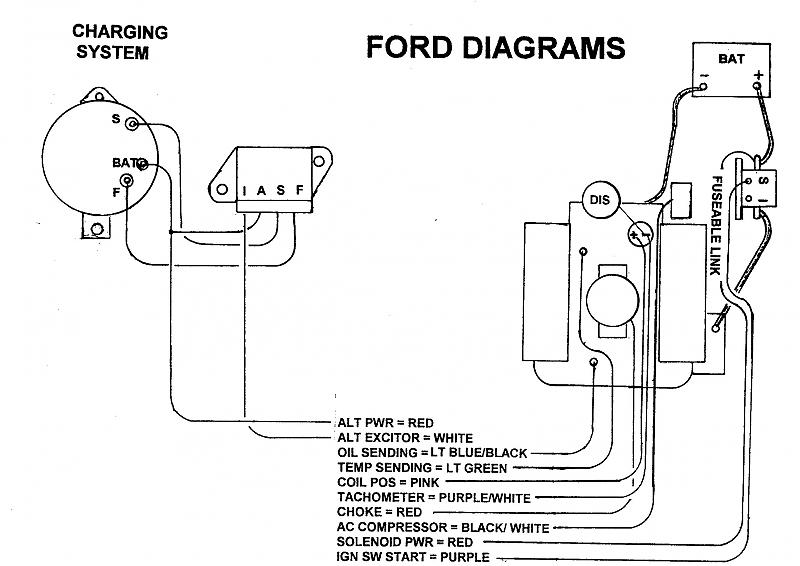
Alternator regulators from Ford should have four posts. They are marked "B" (for Battery, or possibly "A" for Alternator Power) "F" (for Field); "S" (for Stator); and "I" (for Ignition). The back of the alternator should likewise be labelled (Batt, F, S....No I) next to the appropriate lugs.
Here is a generic drawing I drew up and another posted some time ago by another member. Take your pick!
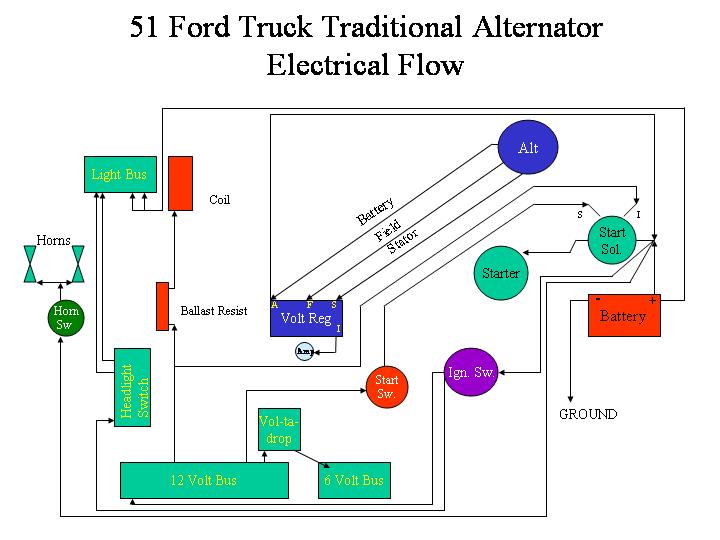
Connect "S" terminal on the Alternator regulator to the "S" (or possibly STA[T]) terminal on the alternator
Connect the "F" terminal on the Alternator regulator to the "F" (or possibly FLD) terminal on the alternator
In the drawings, the "Alt Power" (or Battery) wire coming off the battery lug on the alternator, and co connected to the "A" terminal on the Alternator regulator ends up on the "Batt" terminal of the Ignition Switch - if you have the stock "Amp" guage. Then there is a wire that runs from the "Batt" terminal of the Ignition Switch through the Ammeter indiction loop and ends up on the "Batt" post of the Starter Solenoid. The "I" terminal on the regulator is not used when wired like this.
If you have a Volt meter or "Batt" light, the red wire runs directly to the "Batt" terminal of the Starter Solenoid, and the wire from the "I" terminal runs to the "Batt" light or Volt meter.
I'm assuming this truck has been converted to 12 volt negative ground and you have some other points for power distribution (like a fuse block or the ignition switch) that you are using to distribute power out, and not using the stock 6 volt 30 and 15 amp circuit breakers located on the instrument panel (Which is where the power wire would have gone from the generator regulator "Batt" terminal in a stock 6 volt generator set-up.)
Glad you asked?
Ok now that you are ready to slap me, I'll give you the bad news. If your regulator has BAT, FLD and ARM on it, it is a regulator for a generator not an alternator. I hope you weren't thinking of using the existing generator regulator with the alternator. That's a "no-no."
Alternator regulators from Ford should have four posts. They are marked "B" (for Battery, or possibly "A" for Alternator Power) "F" (for Field); "S" (for Stator); and "I" (for Ignition). The back of the alternator should likewise be labelled (Batt, F, S....No I) next to the appropriate lugs.
Here is a generic drawing I drew up and another posted some time ago by another member. Take your pick!
Connect "S" terminal on the Alternator regulator to the "S" (or possibly STA[T]) terminal on the alternator
Connect the "F" terminal on the Alternator regulator to the "F" (or possibly FLD) terminal on the alternator
In the drawings, the "Alt Power" (or Battery) wire coming off the battery lug on the alternator, and co connected to the "A" terminal on the Alternator regulator ends up on the "Batt" terminal of the Ignition Switch - if you have the stock "Amp" guage. Then there is a wire that runs from the "Batt" terminal of the Ignition Switch through the Ammeter indiction loop and ends up on the "Batt" post of the Starter Solenoid. The "I" terminal on the regulator is not used when wired like this.
If you have a Volt meter or "Batt" light, the red wire runs directly to the "Batt" terminal of the Starter Solenoid, and the wire from the "I" terminal runs to the "Batt" light or Volt meter.
I'm assuming this truck has been converted to 12 volt negative ground and you have some other points for power distribution (like a fuse block or the ignition switch) that you are using to distribute power out, and not using the stock 6 volt 30 and 15 amp circuit breakers located on the instrument panel (Which is where the power wire would have gone from the generator regulator "Batt" terminal in a stock 6 volt generator set-up.)
Glad you asked?
#3
08-25-2009, 08:38 AM
Fleet Owner
#4
08-25-2009, 10:07 AM
Post Fiend
Julie, nice diagrams but a couple comments;
I would run the alt BAT on your Trad diagram from the alt directly to the solenoid, (it is) it needs to be 8 or 10 ga. and have a fusible link. Yes that is how I have mine, Ross, but if you want your stock amp guage to work and show any discharges, then it has to be wired as I described - unless you have a fuse panel, then it should go to the fuse panel - then through the gauge on to the solenoid. Same flow path as the stock wiring, just using different points for distribution other than the 6 volt circuit breakers. Can be done lots of different way, this just seemed like the most direct.
On your 2nd diagram, it seems like "Alt Pwr" and "Solenoid pwr" should be connected?
"If you have a Volt meter or "Batt" light, the red wire runs directly to the "Batt" terminal of the Starter Solenoid"
It's hard to describe this stuff in written post and make sense without being confusing. I have a picture in my mind and know what it looks like, th eproblem trying to convert that to text and make sure that when you read it, your mind develops the same picture.
If you have ANY questions, feel free to ask and I'll try to confuse yousome more.
#5
08-25-2009, 10:27 AM
Fleet Owner
#6
08-25-2009, 10:32 PM
Join Date: Jul 2008
Location: Las Vegas, NV
Posts: 205
Likes: 0
Received 0 Likes
on
0 Posts
#7
08-26-2009, 12:57 AM
Post Fiend
Fact is there are about five different ways it can be done and it depends on whether or not his alternator needs an exciter, type of gauge (think it's a light in the 60)? fuse blocks? rated output? Draw?
So there could be a number of options.
I'm not sure I follow you on the terminating the #8 wire on the screw post of the regulator....did you mean Ignition switch? See, even I get confused!
Trending Topics
#8
08-26-2009, 08:49 AM
Fleet Owner
Your colored drawing shows the BAT wire from the alt (which is #8 or #10 ga) going to the "A" post on the regulator; a lug for that size wire is usually larger than the screw post on a reg. Electrically it may be correct but physically doing it might be difficult.
Yep, I think by '60 they were using an idiot light. Were the ammeters even used then, and if so, did they have a loop or posts? Beats me!
Yep, I think by '60 they were using an idiot light. Were the ammeters even used then, and if so, did they have a loop or posts? Beats me!
#9
08-26-2009, 10:47 AM
Post Fiend
Ah ok.
The older regulator I had (before I went to one wire) had metal tabs and I think was designed to take a one piece nylon plug. But it had flat tabs designed to slide on a (female) connector, and not an "Eye" connector with a machine screw like the generator regulators. So I was able to use a "yellow" slide on connector with a 10 AWG wire (which should be more than sufficient at 12 volts with a 50 or less amp stock alternator). And usually (although I prefer to combine them into a single connector) you can splice them together farther down line (like the second drawing shows).
That drawing was one of the first I did and I could probably dress it up a bit. When I did that one I was more interested in showing signal flow and not so much the actual connect points. And I think this is the first or second time I've used it. So I'll take a look and maybe even color the wires.
See there we go again with the unknowns - alternator rating, does he have any big draw items like fans, wire size needed, etc. etc.
The 60s was a blur to me too!
#10
01-15-2015, 09:10 AM

Senior User
Join Date: Jul 2003
Location: FL
Posts: 322
Likes: 0
Received 0 Likes
on
0 Posts
So, dredging up an old post 5.5 yrs ago rather than restarting another one.
Looking for more info on the "I" terminal on the VR. This universal harness has a wire that labeled "alt excite" and the scant 'literature' that came with it babbles about a resistor or light. I've seen some schematics/drawings online that show a 500ohm resistor in parallel with a light.
When I think of "alt excite", it means I'm providing the excitation of the fields in some way (depends on windings of alternator). These descriptions make it seem more of a monitoring function -
Julie's post above talks about sending the "I" terminal to a voltmeter or light. But a light and a meter would work differently. If it provides a voltage reading for a voltmeter, that same voltage would turn a light on - which is not what you want - unless there's more of a circuit missing (some sort of diode or reverse-current relay) to turn the light on when the battery is discharging that the "I" terminal can sense. So her post is very confusing.
At best, it seems the "I" terminal can be left alone...unless it truly is 12V into the excitation fields to get the alternator going (an alternator, unlike a generator, requires voltage to 'kick start' it).
Sooo....anyone care to attempt to clear up my confusion? I'm normally pretty good with auto-electrics and electrics in general (to include a little formal training).
If it matters, this is an early-style alternator from an '89 Mustang (which seems to have been a non-standard option as most had the later style alternator)...and I can't find a wiring diagram online for it...so far.
#11
01-15-2015, 10:03 AM
Fleet Owner
Thanks to the internet, "Julie's" diagrams, complete with errors, will likely outlive me. "She" went in and deleted all the ones that were correct after she was banned.
See below, I don't completely understand the function of the I terminal, but it appears to bootstrap the fields? Note that the "coil resistor" and "Key Switch Acc." are completely different, IGN vs ACC???
See below, I don't completely understand the function of the I terminal, but it appears to bootstrap the fields? Note that the "coil resistor" and "Key Switch Acc." are completely different, IGN vs ACC???
#12
01-15-2015, 11:54 AM
Senior User
Join Date: Jul 2003
Location: FL
Posts: 322
Likes: 0
Received 0 Likes
on
0 Posts
Thanks to the internet, "Julie's" diagrams, complete with errors, will likely outlive me. "She" went in and deleted all the ones that were correct after she was banned.
See below, I don't completely understand the function of the I terminal, but it appears to bootstrap the fields? Note that the "coil resistor" and "Key Switch Acc." are completely different, IGN vs ACC???
See below, I don't completely understand the function of the I terminal, but it appears to bootstrap the fields? Note that the "coil resistor" and "Key Switch Acc." are completely different, IGN vs ACC???
I've seen diagrams without the "I" terminal hooked up. I've also read that it has to be hooked up. So, I'm starting without it.
I think the reference to the ballast resistor is misleading. While it would probably work OK, most of the diagrams I've found show a 500ohm resistor in parallel with the idiot light...although, I've also found a page that said it won't charge w/o this wire and if it doesn't charge, to add an 8K resistor...and if it still doesn't charge, keep adding them until it does. It must be true...it's on the internet!
 I'm sure there are "workarounds" for many things...
#13
01-15-2015, 02:32 PM
Fleet Owner
Doesn't make sense to me. I can believe a resistor in parallel with the light, to ensure trigger current when the bulb burns out. I don't see how the light could be replaced with a voltmeter; they don't usually consume any significant current (maybe the resistor is in parallel with that?).
There are threads on converting the Ford alt's to 1-wire operation, I'd be sorely tempted to go that route. Is it really a Bosch alternator? I've see Boschs that needed 6 wires for some reason?!?
There are threads on converting the Ford alt's to 1-wire operation, I'd be sorely tempted to go that route. Is it really a Bosch alternator? I've see Boschs that needed 6 wires for some reason?!?
#15
01-15-2015, 05:53 PM

