
Ford Racing Mass air conv. kit?
#1
 05-23-2008, 11:12 AM

Join Date: Jun 2002
Location: Woodbridge NJ
Posts: 812
Likes: 0
Received 0 Likes
on
0 Posts
Is anyone using the Ford Racing mass air conversion kit on a 351W engine?
Part # (manual trans) M-9000-T50 or (automatic trans) M-9000-T51
Those kits are designed to for 5.0L and 5.8L engines. According to the instructions they work for both firing orders.
I'm currently replacing my 1991 5.0L and installing a 1989 5.8L engine.
My question is will this kit work with the new 5.8L engine, being that the firing order is different and I'm changing the injector pulses from bank to sequential order?
Any advice would be helpful.
Thanks,
Jerry D.
#2
05-23-2008, 12:49 PM
Yeah.. I have been running one for 8 years now. I had to change the injector firing order on the overlay harness because the I got the kit for the non-HO order(didn't even know they made different harnesses for the 2 firing orders at the time). This is dumb easy as long as you can use a soldering iron, just need to move 4 wires.
My 5.8 runs like a stock motor, except it's got more power.
My 5.8 runs like a stock motor, except it's got more power.
#3
05-23-2008, 05:06 PM
Laughing Gas
#4
05-24-2008, 05:31 PM
Join Date: Jun 2002
Location: Woodbridge NJ
Posts: 812
Likes: 0
Received 0 Likes
on
0 Posts
Yeah.. I have been running one for 8 years now. I had to change the injector firing order on the overlay harness because the I got the kit for the non-HO order(didn't even know they made different harnesses for the 2 firing orders at the time). This is dumb easy as long as you can use a soldering iron, just need to move 4 wires.
My 5.8 runs like a stock motor, except it's got more power.
My 5.8 runs like a stock motor, except it's got more power.
Awesome! I finally found someone that has the same setup as me...
Can u just break it down for me what I have to do?
I suck at soldering so I'm gonna have my buddy do the job for me. And Idon't want to explain it wrong to him.
Thanks in advance!
Jerry D.
#5
05-24-2008, 05:34 PM
Join Date: Jun 2002
Location: Woodbridge NJ
Posts: 812
Likes: 0
Received 0 Likes
on
0 Posts
#6
05-25-2008, 07:17 AM

Junior User
Join Date: Sep 2007
Location: Mt.Pleasant, Texas
Posts: 88
Likes: 0
Received 0 Likes
on
0 Posts
i've bought the same kit, about 5 months ago , new..I did the same thing Paul did , switching 4 wires, and soldering them , for the 5.8 firing order, which is the same as the H.O. order....a company in Mich. Called "Dunnrite performance".....Ford Racing gave me his phone number, and I called him, a REAL good guy..........if u have a E4OD tranny, you will need a Baumann Controlls computer "BAUMANATOR" for that too....A DAMN good product, if u ask me !!!!...all together cost was around 900$
#7
05-25-2008, 09:08 AM
Join Date: Jun 2002
Location: Woodbridge NJ
Posts: 812
Likes: 0
Received 0 Likes
on
0 Posts
Trending Topics
#8
05-25-2008, 09:38 AM
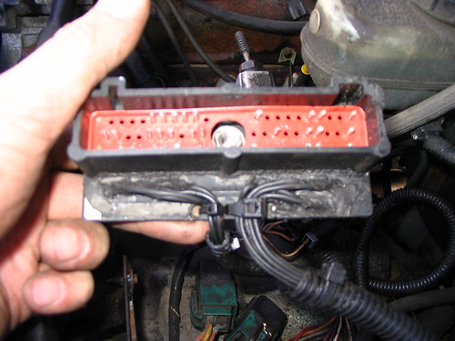
So you need to switch the wires for injectors 5 & 4 and 3 & 7, the idea is to create the 13726548 order from 15426378. You can use a multimeter to identify which wire belongs to which injector at the computer end, label them and then strip off any weatherproofing before attemptng to move the wires. You can see from the pic below I applied black silicone sealant to the board after making the modification.
#9
05-25-2008, 08:29 PM
Junior User
Join Date: Sep 2007
Location: Mt.Pleasant, Texas
Posts: 88
Likes: 0
Received 0 Likes
on
0 Posts
#11
05-26-2008, 02:17 PM
Join Date: Jun 2002
Location: Woodbridge NJ
Posts: 812
Likes: 0
Received 0 Likes
on
0 Posts
Sorry to go over this again guys. I think I'm over thinking this.....I just want to make sure I'm getting it right.
The # 5 injector wire shoud be removed and soldered in # 3 position on the circuit board.
The # 4 injector wire should be moved to the # 7 position
The # 3 injector wire should be moved to the # 5 postion
The # 7 injector wire should be moved to the # 4 position.
And the numbers on the injector plugs will still go in the 1-2-3-4 --- 5-6-7-8 positions
Jerry D
#12
05-26-2008, 02:32 PM
The # 5 injector wire shoud be moved to the # 3 position on the circuit board.
The # 4 injector wire should be moved to the # 7 position...
The # 3 injector wire should be moved to the # 5 postion...
The # 7 injector wire should be moved to the # 4 position...
And the numbers on the injector plugs will still go in the 1-2-3-4 --- 5-6-7-8 positions. Jerry D
#13
05-26-2008, 07:29 PM
Join Date: Jun 2002
Location: Woodbridge NJ
Posts: 812
Likes: 0
Received 0 Likes
on
0 Posts
Paul,
Thanks again!
Ok, so i removed the overlay ...no prob. I had to remove some black sealant to expose the solder points on the circuit board....must have came from Ford like that.
I ID and marked all 8 wires and the 9th wire (common wire) on that side of the board.
Now it's solder time!
Which would be better....cut and swap the wires approx. 5-6" up from the board or solder and swap directly on the circuit board?
#14
05-26-2008, 08:51 PM
Better to remove the wires from the board and put them back where you want, connections in the wires will always corrode and be a source of problems. BTW.. a solder removal tool or solder wick will help here, you can heat the joint and suck out the old solder, and then apply fresh solder after you place the wires. You don't need a monster soldering iron either, a 15w or 20w unit is plenty.
#15
05-27-2008, 03:57 PM
Junior User
Join Date: Sep 2007
Location: Mt.Pleasant, Texas
Posts: 88
Likes: 0
Received 0 Likes
on
0 Posts