When you click on links to various merchants on this site and make a purchase, this can result in this site earning a commission. Affiliate programs and affiliations include, but are not limited to, the eBay Partner Network.
Hi,
I bought seats out of a 2012 F350 SD crew. Leather - heating & cooling. I'll be putting them in my 97 F350 OBS Crew.
I've watched/reviewed many of the different videos out there to enable movement on the chairs, which basically removes the need for computers except for heating and cooling. My concern is this: if I turn on the Heat and leave it on, the TADs unit will probably burn out. The under seat computers control that by all the sensors in the seat.
So does anyone have ideas on how to use the computers? Do I need to use the computers to control hot/cold on the seats? I can build out switches, I can reverse polarity the wires and I have wiring diagrams. I just don't know how the switch on the dashboard tells the computer to go from OFF - Lo - Med - Hi - OFF cycle on the heat (or cool). I believe switching polarity on the two power wires does the hot/cold switch thing. It's the lo-med-hi switching that I am wondering about.
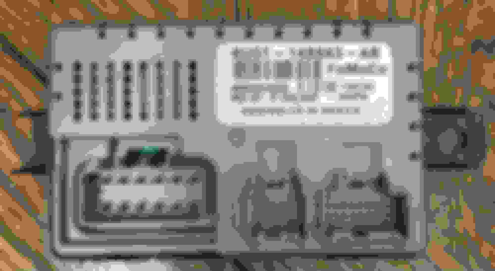
I believe you should, you will find that there is a set of wires twisted together (VT/OG and GY/OG), they are the MS CAN bus wires, these heated/cool modules are very simple to control. All you need to do is send one data packet to it telling it what you want. An arduino with a CAN shield and two buttons and a few leds would make this work easily.
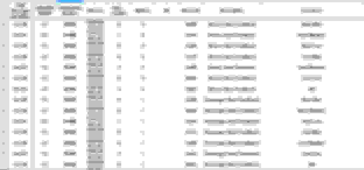
Here is the CAN packet that the HVAC sends to the heated/cooled seat module (everything is in hexadecimal, as long as the heated/cool seat module see this packet every second it will stay on)
You could use a toggle switch on the TED to switch between hot/cold but there is no easy way control the temperature and fan speed, the module does this by varying the current (pwm) to the TED for the different heat/cool settings and setting the fan speed (pwm again if I remember right).
Thanks ifrythings! this was a lot more than I bargained for - but definitely something I can try. I've wanted to have a good reason to do the arduino thing... now I have one - starting from scratch...
If I go this route - I'll document the process.
Thanks ifrythings! this was a lot more than I bargained for - but definitely something I can try. I've wanted to have a good reason to do the arduino thing... now I have one - starting from scratch...
If I go this route - I'll document the process.
Being new to Arduino - any recommended pairing (Arduino and Can Bus cards)? There is a lot of stuff out there....
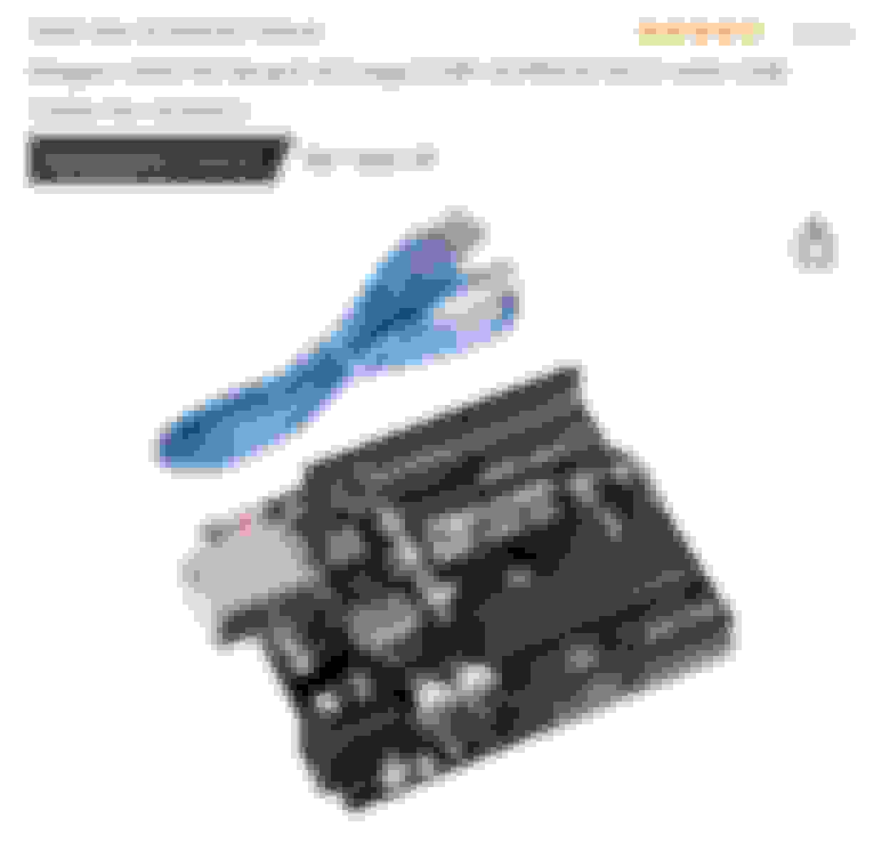
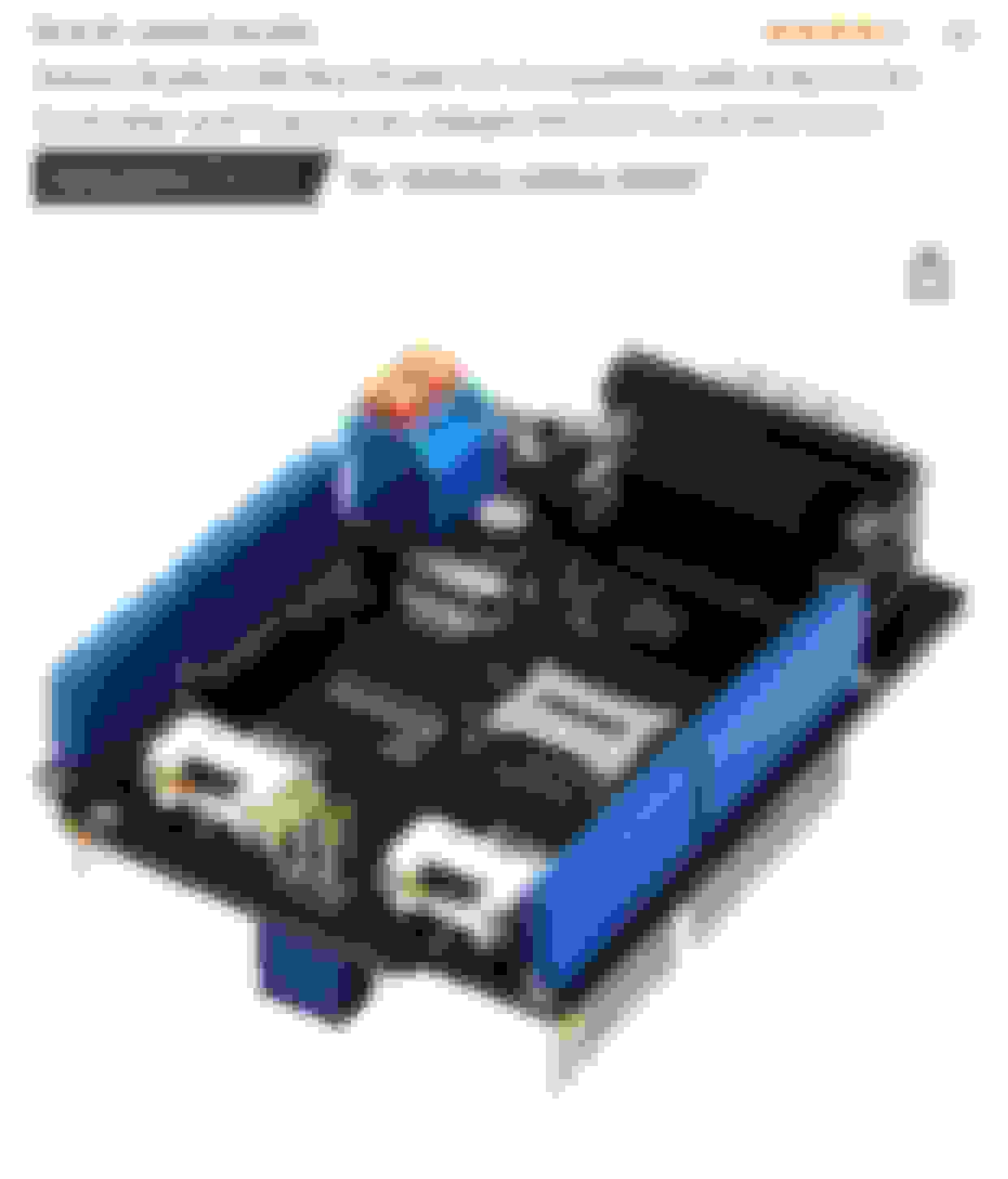
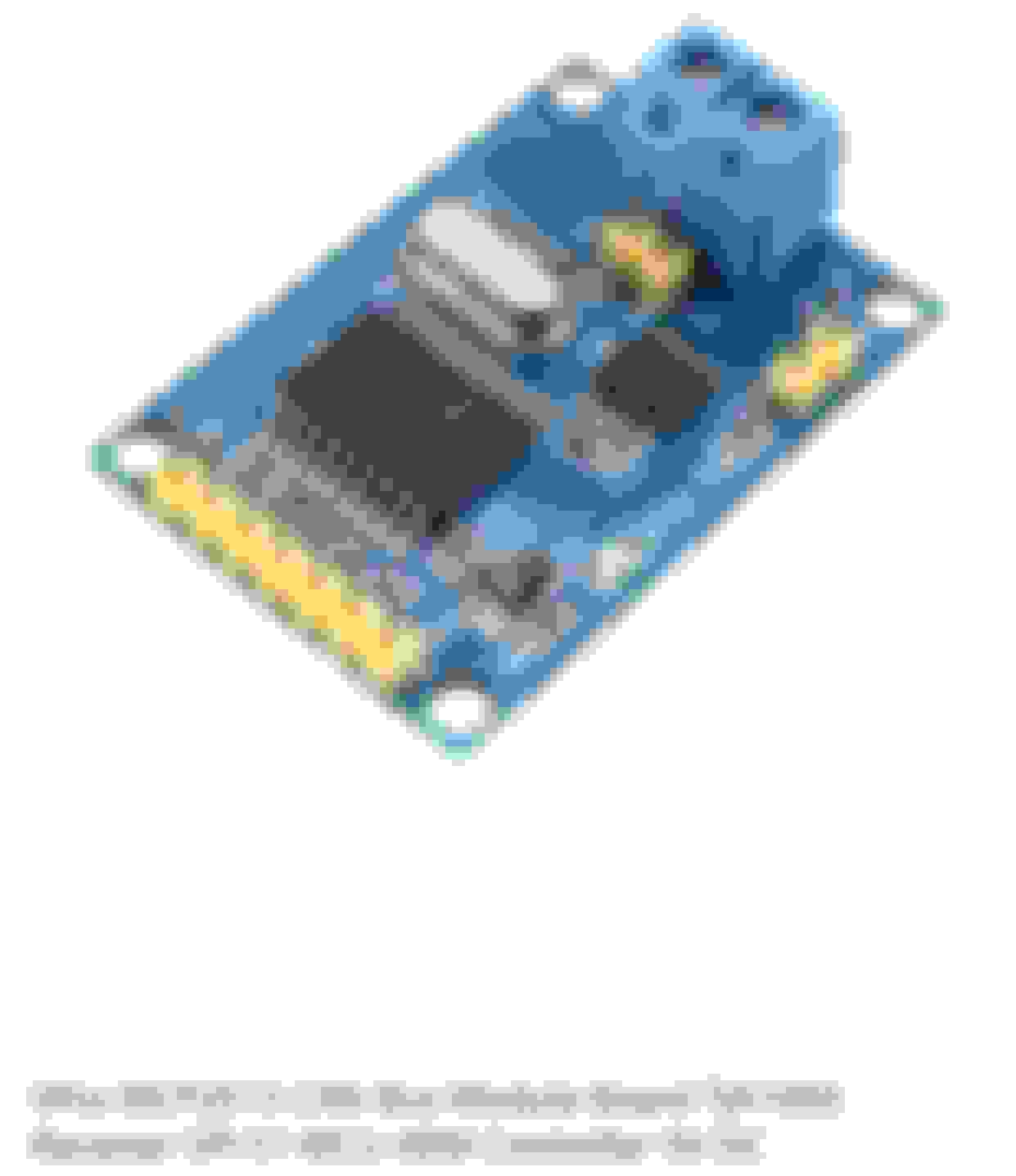
Being brand new to arduino, I would start out getting an UNO and a CAN bus shield, here are a couple examples below, look and shop around as these are pretty much all the same but the prices vary immensely between sellers.
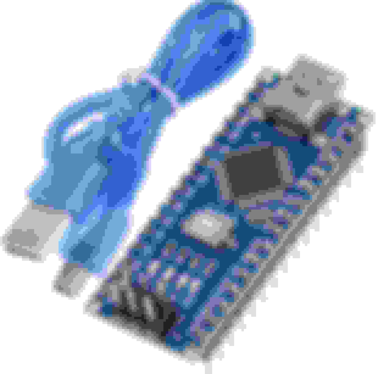
If you want to go a bit more advance you can get an arduino nano and a CAN bus board and hook up a few wires.
Just to add a bit more info, the Dual Climate controlled Seat Module (DCSM) sends out a data packet(or message) that gives you the current status of the seats, this would be a good thing to monitor so you actually know what the seat is doing.
This DCSM packet is easy to read from the CAN bus and you could use it to light up the high/medium/low leds for example.
If I was going to make a stand-alone controller for this (personally I would use a touch screen) I would get 4 push buttons, 2 for the drivers seat and 2 for the passenger seat for heated/cooled setting, 6 red/blue bicolour leds, 3 for each seat (high/med/low) and red would be for heat and blue for cool. I would have the arduino send out the 0x124 CAN packet to control the DCSM and use the DCSM 0x125 packet to tell the arduino what leds to light up/status of the seats.
Thanks for that other code picture with the last column - very helpful. So I bought these switches - sorta goes with the 97 dash style. They wanted 150+shipping for the 2013 dash controls - all 1 unit and I only needed the switches. These ones (1 switch per seat) will control both heat/cold and the top leds change color scheme depending on hot/cold - I thought that was pretty efficient. I just hope they work for the application. Documentation has begun!
I called this company and got a local distributor to get them for me. They don't sell direct. https://katzkin.com/degreez/. About a 40 bucks each switch plus S&H. No guarantee they will work, but the guy said there are a bunch of wires coming off the back of each switch. I want to say 11 wires?? I'll let you know when I get them.
UPDATE: Seats move per OEM specs through the under-seat computers. I have not removed the computer or cut any wires. Also - the switches/Arduino programming works to trigger an appropriate CAN BUS message to the under seat computes, but I have not yet done the CAN BUS messaging. That's next. The switches work pretty neat. Lots of wires on the 2 breadboards Each board mimics a switch, and has 2 buttons. The button push (left is hot, right is cold) rotates thru the corresponding LEDs round robin, starting with 3 on, then 2 on then 1 on then all off. A button push turns off any indicator for the other button as well as sets up sending the appropriate CAN BUS message.
I've got that programming left to do for the Arduino. I've got 5-volt Arduino relays and pin connectors coming to hardwire and power 12 volt auto relays to actually do the work on the switches. I don't want the 12v auto switch pulling too much from the 5 volt Arduino. LEDs don't take much but eventually, I want to put a POT on the 12v to be able to dim the LEDs.
I'll share the wiring diagrams when done. Below you can see the right side is where I started and the left side was the repeat setup ( a bit neater looking). On the left side there is a bank of 3 blue LEDs behind all the red wires.
Looks good, if you want to save some jumper wires, use your resistors as jumpers from the negative rail on each side of the breadboard, then just link each side of the breadboard with a jumper.
Also if you wanted to make it more compact you could get bipolar leds that are red/blue and save you 3 leds and dropper resistors.
//the CAN send (this is sent if the switch selects high. Similar for all the others).
CAN.sendMsgBuf(0x124, 0, 8, CANMsg_HOT_High);
I just think my message is wrong.
I have 2 arduino setups (one monitoring what's coming out of the main - and the main is hooked up to the chairs CAN BUS wires. Chair computers have proper voltages as the switches moving the positions work. Both chairs are wired to the CAN BUS (in case the driver computer needs to see the passenger computer - but I don't think so as what if one went bad - the other still would work).
The Dual Climate Control Module doesn't need to talk to the drivers seat module, it only listens for the message from the HVAC controls.
I'm not sure which CAN library you are using but here is a quick sketch that works, you will have to add in your switch(es), this will transmit the CAN message every ~1s and also display anything it receives on the CAN bus on the terminal. Make sure to download the CAN library at the top of the sketch and add the library to Arduino.
That's a huge step forward. Now I'm getting the following (first line)... I put a Serial.Print in the loop - that does show up so I'm assuming this is coming from the control module?

 11-03-2021, 06:49 PM


 Each board mimics a switch, and has 2 buttons. The button push (left is hot, right is cold) rotates thru the corresponding LEDs round robin, starting with 3 on, then 2 on then 1 on then all off. A button push turns off any indicator for the other button as well as sets up sending the appropriate CAN BUS message.