When you click on links to various merchants on this site and make a purchase, this can result in this site earning a commission. Affiliate programs and affiliations include, but are not limited to, the eBay Partner Network.
this was going to be just about the tranny crossmember build, but needed some background. I just realized this is going to get excessively long so I will break it into a few posts. First the background:
As many of those here that follow my posts already know I have been helping my friend Gary (JGP1952) with his F1 build. This weekend we finished the tranny support crossmember far enough to test install it.
Here is background for the build so far and how it affected the crossmember design, and how it was built.
His truck is a 1952 F1 he bought as a disassembled pile of parts the PO had sandblasted and epoxy primed, with a monkey face front doghouse and no engine or tranny. I got involved with the project when Gary introduced himself on here and I offered to come look at what he had. On close exam I could see the primer was hiding a lot of problems, and told him I could help him learn to do the rust repair it was going to need. Gary turned out to be eager and willing to listen and learn, and a strong friendship was formed.
Fast forwarding to the crossmember: Gary decided to use a 2007 Ford 4.6 mod motor from a Mustang GT (3V) and matching 3650 5 speed stick from the same car that he found online. A nice choice, but thanks to FoMoCo one having many unique problems that would need to be solved.
Gary also decided he liked the beam axle and new Posey dropped springs the truck came with but wanted power steering and lower front end, so a Toyota PS box was sourced and the axle sent to Sid for a 3" drop. A custom box mount was made based on a sketch I had done in the past when a mount was not available.
We first set the engine into the frame centered and when we found the OEM aluminum engine mounts were potentially usable with custom frame mounts we got excited this was going to be an easy install! The engine came with nice tuned OEM cast headers, and the passenger side fit great. But this is where things started going south. The driver's side also fit, but the outlet was about 1" away and pointed directly at the steering column shaft. Uh oh! We tried putting the pass side manifold on the driver's side, no go. Gary looked online for headers for this engine, but all offerings were for the Donor Mustang chassis so all had the outlet in the same place. Gary talked to hte people at Sanderson to see if they had a header that might work or one that could be modified to work. They only made one set for this engine and they were for that same chassis application. Since the Sanderson set were made fro heavy weight mild steel tubing they could possibly be modified to work??? An order was placed and after several followup phone calls a set arrived 7 weeks later. Again the pass side fit beautifully but not the driver's side. We tried moving the engine side to side, up/down, forwards and back but no cigar even with modifications. Gary had picked up some sections of pipe castoffs from a local muffler shop to possibly use to modify the header, and without the header in place we tried to see what kind of arrangement would work. With the engine centered there was barely enough room to get a single pipe between the engine and frame and not enough space between the mount and box for 4 pipes to pass even in a row. By moving the engine asfar to the passenger side as far as practical while still having that header useable (1") a space opened up where 4 pipes could fit in a classic cloverleaf block hugger collector configuration.
More extended phone conversations with Sanderson revealed they were unwilling to build a block hugger header without a prototype to work from, so they sent a raw flange, a collector cone and a bunch of pipes for us to play with. The daunting task of building a header from scratch with the limited selection of pipe they sent was not one we decided we wanted to tackle. But it did show us it was possible. Exploring the local DIY store's plastic plumbing parts inventory it was discover that an available size PVC pipe fitting had an almost identical outside diameter to the steel tube. Gary bought a bunch of elbows, 45s and straight tubing and set to work making a 3D jigsaw puzzle that needed the parts cut to fit! But he pulled it off!!! he built a prototype plastic header that would fit. He tacked some steel strap to the flange and used screws to attach the plastic pipe so it could be shipped to Sanderson without falling apart.
OK, now lets jump ahead to the design and fab of the cross member.
The 3650 tranny uses a cast aluminum, rubber and steel laminated OEM mount located near the front of the tailshaft housing. There is a rather soft rubber formed center with a engineered shape that can be moved by hand. it is shaped like a flat center with an angled wing on each end. There is a single center bolt going up thru an isolated bushing in the cast aluminum top into the transmission and a pair of studs pointing down attached to the steel bottom plate that bolts to the crossmember. since Ford obviously spent a lot of time and money developing this mount we felt it was important to use it on Gary's truck. The original crossmember that mounted the pedals and MC had been cut in the center by the PO, and only the stubs were still attached to the frame. This OEM crossmember was an important structural member, not only did it provide a mounting point for the controls, but also kept the frame from bowing or splaying when weight was applied to the running boards. Even though Gary was going with swinging pedals and firewall mounted brake and clutch MCs we still wanted to return the transmission crossmember to providing that structural strength but still have a removable center in case the tranny needed to be removed without needing to pull the engine. The final design parameter we determined was that the bottom of the tranny mount needed to be 2.25" below the bottom of the frame to give clearance for the front U joint below the floor and ideal engine angle. With the engine mounts we were using. (More on the mounts coming up in a later installment).
I drew up several versions of full sized crossmembers, in Corel draw! using it like a cad program, to get the creative juices flowing, finally zeroing in on a 3 piece design that fulfilled all the design parameters including ease of fabrication with the tools available in my shop and at Gary's. I settled on making it from 1x1" 1/8" wall square tubing since the metal recycling yard near my house had it new in 20' lengths, by the full length, 1/2 length or foot. we needed about 6' so a 1/2 length made to most economic sense with enough left over in case a piece was miscut or for future use. It would also be plenty strong. after adjusting the details in the drawing a number of times, I declared the design complete and ready to fab. here's one of the close to final versions I sent Gary for his approval:
I was still tweaking the details after this version. Note the transmission mount cradle is offset 1" to the passenger side.
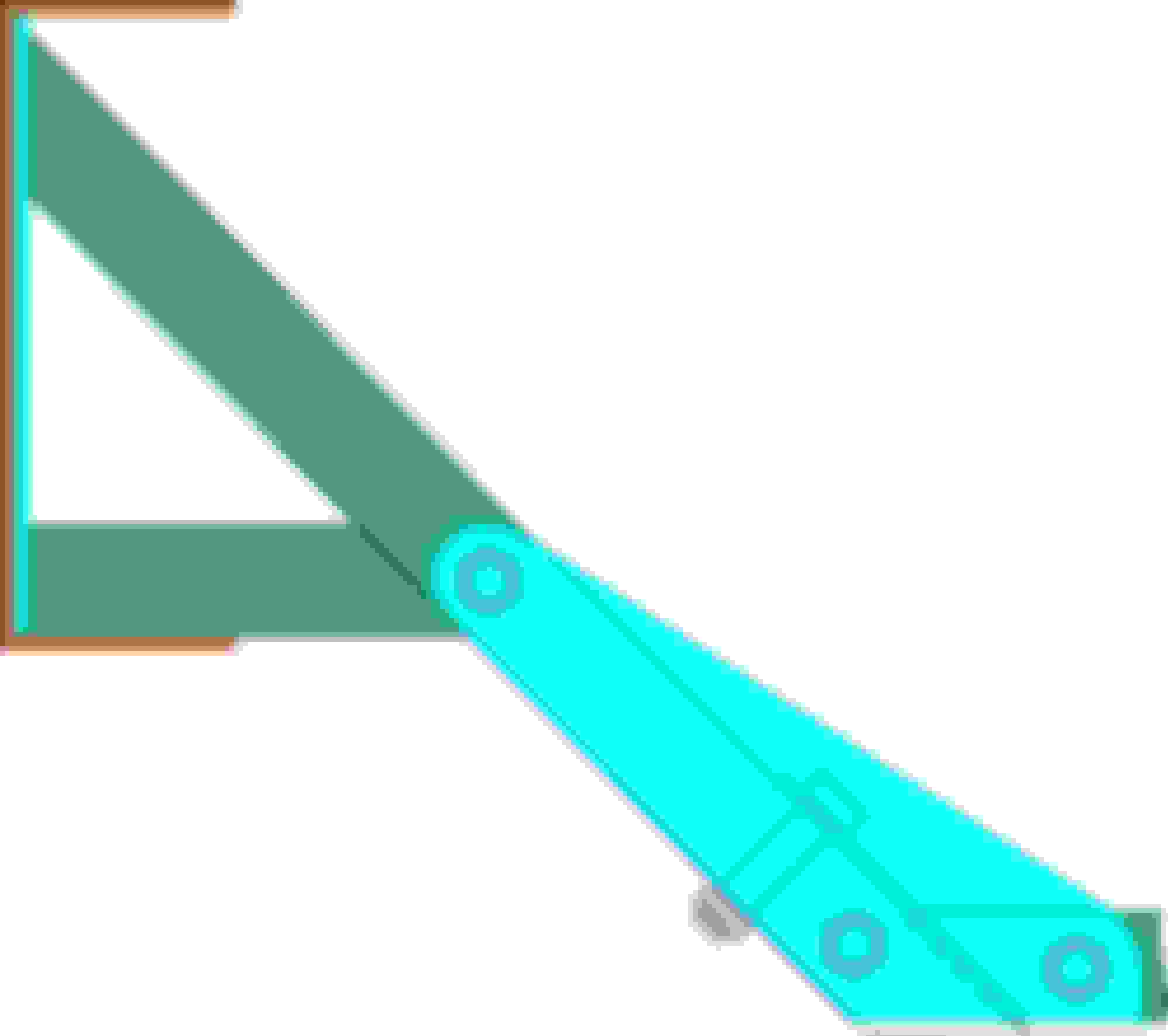
Next step was for me to build a full size jig to keep the parts aligned while welding and to assure it would come out the correct size and straight with the correct drop below the frame. the parts colored turquoise are 1/8" plate, the parts colored green are the square tubing. The frame rail cross sections are rust colored. (My sense of humor coming out... ) bolts for attaching to frame are not shown. All bolts are 3/8" thru crush tubes.
Fab is next.
Shoo, It's all bolt in as you will see in a few minutes.
Tony, yes Gary did an excellent job on the header prototype. Sanderson was so impressed when they received it they said they would build a jig from the prototype adjusting the bend radiuses to smooth the flow, (PVC plumbing manufacturers need to make various radius elbows and 45s for us hot rodders dman it!) and were building the header immediately so they could take Gary's prototype and completed header to a major show the next week to show what they can do, then powder coat it right after the show and send the finished header to him.
Tony, hows your truck coming, any progress? Need me to come give you a hand again?
Continuing the crossmember build, the fabbing starts:
I printed out full sized prints of each end for reference in the shop.
end with finalized details
I used the print to lay out the various parts on the square tube and 1/8" plate. I cut the tubing with my chop saw and the plate with a cutoff disk on my 4" angle grinder. The 45* cuts were a challenge, the blade of the chop saw wanted to bend during the cut. a stationary band saw would have been a better choice had I had one available. I trued up the cuts and plate edges with sanding disk and files. I clamped the 4 doubler plates together and drilled them on the drill press so they would be interchangeable, same with the 2 end plates.
The next step was to make an assembly jig to hold the parts in alignment for layout and welding. I screwed together (2) 33-5/8" lengths of 3/4 x 12 MDF shelf board as the base for the jig and carefully transferred the crossmember layout to the MDF. I used the mounting holes in the end plates to screw the plates to the ends of the jig. I screwed small mdf blocks to the jig board to hold the tubing pieces I had cut in place.
I used one of the doublers and a 3/8" transfer punch to mark the hole locations in the square tubes, drilled the holes out to 1/2" size to insert the crush tubes.
First issue faced. the 3/8" ID tubing I had to make the crush tubes was slightly larger than 1/2" OD. I didn't have a 33/64" drill so I needed another solution. After experimenting with step drills and burrs I had nothing was the right size. Finally an idea came to me: I cut a 7" long length of the tubing, chucked it into the drill press and held a flat file against the outside of the spinning tubing trying to keep it moving along the length to reduce it evenly until it read 0.50 on my calipers. I tested it into a drill hole and it was a snug fit. I cut and deburred 1.24" long lengths of the tube and use my bench vise to press them into place. A couple taps of a hammer and the tubes stuck out 1/8" on each side of the square tube. I cut and filed another length of tubing the same way so I would have enough for the 8 crush tubes I needed. I welded around the tubes and then ground and sanded them flush. A quick pass with a 3/8" bit made quick work of cleaning out the tubes. Now everything could be set in place in the jig for tack welding and so I could accurately size and cut the cross bar. I cut and added the crush tubes to that piece, tacked it all together on the jig and took it to Gary's where we would make the 2 1x 1/8" x 4-1/2" tabs that would support the main bar (along with the 4 doublers), he would do the final welding and we would make the plate the tranny mount would sit on.
1" x1/8" wall tubing braced this way should be plenty strong, as strong as the 3 sided frame itself over 33 -3/4" and definitely stronger than the original stamped sheet crossmember that was originally there. This is an all aluminum engine and tranny, with the engine sitting on it's mounts I can lift the tailshaft by hand. I stood on a 4' length of the tubing supported at each end, and my 270# didn't deflect it any noticeable amount. I'm not at all concerned about strength, the stresses are supporting the weight of the transmission, and resisting the splaying of the frame (top tipping outwards) from weight (only when) on the running boards. Since this truck will not be used for carrying loads on the running boards or in the bed needing unloading, or for people riding on them such as machine gunners making a hit That stress will be minimally applied.
Thanks for your concern tho.
I would rethink using 1'' tubing for a stressed crossmember.
I agree that cross member is not going to add any significant structure (stiffness) to the chassis in an area where it can be very beneficial. 1" tube just doesn't have enough bending stiffness unless it is in a triangulated truss configuration. However the design shown should do an adequate job of 'holding up' the rear of the trans which is pretty much all the tail end of the trans needs.
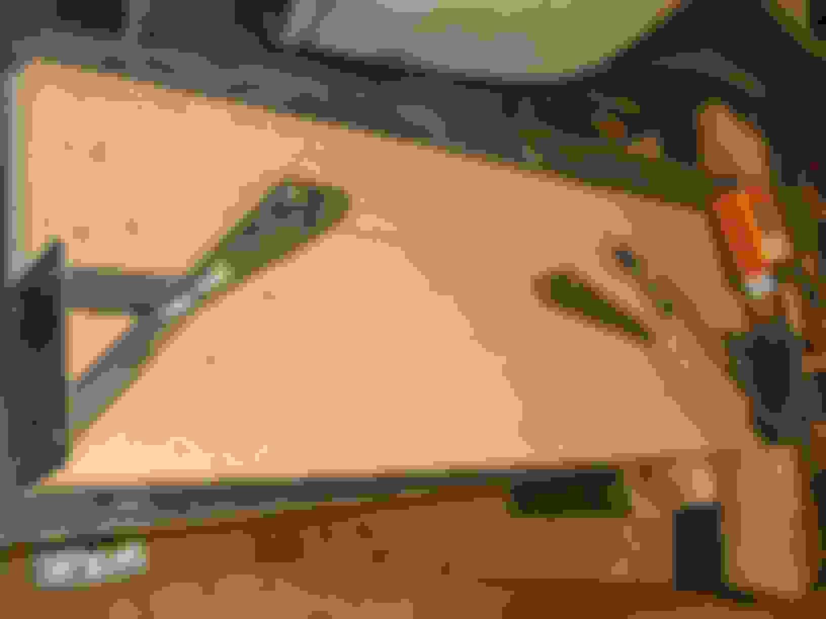
Here is the completed crossmember temporarily bolted together for installation: All bolts will be switched for grade 5 or 8 with washers and nylok lock nuts at final assembly.
assembled show from rear
and same from lower front
frame drilled and crossmember bolted in place. Angle gauge says 4.5 degrees down, withing acceptable target range. Gary likes it so much he wants to dress up the welds some more and send it out to be powdercoated.
I agree that cross member is not going to add any significant structure (stiffness) to the chassis in an area where it can be very beneficial. 1" tube just doesn't have enough bending stiffness unless it is in a triangulated truss configuration. However the design shown should do an adequate job of 'holding up' the rear of the trans which is pretty much all the tail end of the trans needs.
If you look at the design you'll see it is a triangulated truss configuration. Have you ever built anything from 1/8" wall (not the typical hardware store 1/16" wall stuff) square tubing? it is extremely stiff. As I stated above, the forces it needs to resist are very low in this area of the frame. It is much stiffer and stronger than any aftermarket offering including the OEM one. This truck will not be going off roading, carrying very heavy loads or doing wheel stands at the drag strip. If you don't think it is strong enough, feel free to not copy the design. Gary and I are plenty satisfied.
If you look at the design you'll see it is a triangulated truss configuration. Have you ever built anything from 1/8" wall (not the typical hardware store 1/16" wall stuff) square tubing? it is extremely stiff. As I stated above, the forces it needs to resist are very low in this area of the frame. It is much stiffer and stronger than any aftermarket offering including the OEM one. This truck will not be going off roading, carrying very heavy loads or doing wheel stands at the drag strip. If you don't think it is strong enough, feel free to not copy the design. Gary and I are plenty satisfied.
I see what you are going with I would have done it some what different but Monday morning QB is the easy part of a forum
Looks good. Pretty over engineered for a trans mount. I think the thick wall 1" will do fine with the torsional forces the motor is gonna throw at it. Any reason you made both the outside and inside mounts removable?
If you look at the design you'll see it is a triangulated truss configuration. Have you ever built anything from 1/8" wall (not the typical hardware store 1/16" wall stuff) square tubing? it is extremely stiff. As I stated above, the forces it needs to resist are very low in this area of the frame. It is much stiffer and stronger than any aftermarket offering including the OEM one. This truck will not be going off roading, carrying very heavy loads or doing wheel stands at the drag strip. If you don't think it is strong enough, feel free to not copy the design. Gary and I are plenty satisfied.
You should be satisfied. I've read your other threads and you do fantastic work. I've learned a ton from your metal working threads. If you re-read my post I did point out that what you had done was good for what you needed. I'm sorry I seem to have upset you. My observations are not without substance. I am a Mechanical Engineer with over 40 years of experience. I do this stuff 5 days a week and have a decades of experience in structural design and analysis.
 08-30-2015, 06:18 PM