3 VOLTS AT COIL+.....RESISTOR WIRE FAILURE????
#16
 07-18-2015, 06:54 PM


 The only variable would be the ballast resistor rating provided by MSD ..
#17
07-18-2015, 07:02 PM

#18
07-18-2015, 07:04 PM
Good .. The sole purpose for the ballast resistor/resistor wire is to protect the coil and or points in the case of a points distributor ..
#20
07-21-2015, 09:45 PM
Redroad (or anyone), I need some advice again. I opened up the wiring harness tonight and found the pink wire. It starts under the dash behind the glove box and goes over the heater controls, behind the instrument panel and then towards the firewall where the wiring harness goes through the firewall on the drivers side. Only it must terminate before it goes through the firewall because I don't see the pink wire coming through the firewall......So am I correct in assuming I can just clip the pink wire anywhere I want (like right behind the instrument panel where I found it?
Ok here's something that threw me for a loop and has stopped my progress until I can get some advice.... In your instructions on your diagram you told me to "test for 12v at the red wire in the plug connector that plugs into the ignition box." I tested the red wire at the plug and there is NOT any voltage whatsoever with the key on!!! I even tested for voltage when cranking the motor and still nothing!!!
Question....Even if the pink wire is damaged, I should still have 12 volts at the red wire, correct or is that wrong? I assumed I'd have 12v at this plug, but nothing. However, with that said, I do have 12v on the white wire. Am I supposed to have 12v at the white wire with just the key on and not running? Why do I not have 12v at the red wire, but I do at the white wire?
I haven't cut the pink wire and hooked up the ballast resistor yet because I'm not sure what this mean by not having 12v at the red wire in the plug. I need some advice on what to do next and what this all means before I go cutting wires. What do I do now?
#21
07-22-2015, 09:07 AM
Redroad (or anyone), I need some advice again. I opened up the wiring harness tonight and found the pink wire. It starts under the dash behind the glove box and goes over the heater controls, behind the instrument panel and then towards the firewall where the wiring harness goes through the firewall on the drivers side. Only it must terminate before it goes through the firewall because I don't see the pink wire coming through the firewall......So am I correct in assuming I can just clip the pink wire anywhere I want (like right behind the instrument panel where I found it?
Ok here's something that threw me for a loop and has stopped my progress until I can get some advice.... In your instructions on your diagram you told me to "test for 12v at the red wire in the plug connector that plugs into the ignition box." I tested the red wire at the plug and there is NOT any voltage whatsoever with the key on!!! I even tested for voltage when cranking the motor and still nothing!!!
Question....Even if the pink wire is damaged, I should still have 12 volts at the red wire, correct or is that wrong? I assumed I'd have 12v at this plug, but nothing. However, with that said, I do have 12v on the white wire. Am I supposed to have 12v at the white wire with just the key on and not running? Why do I not have 12v at the red wire, but I do at the white wire?
I haven't cut the pink wire and hooked up the ballast resistor yet because I'm not sure what this mean by not having 12v at the red wire in the plug. I need some advice on what to do next and what this all means before I go cutting wires. What do I do now?
Ok here's something that threw me for a loop and has stopped my progress until I can get some advice.... In your instructions on your diagram you told me to "test for 12v at the red wire in the plug connector that plugs into the ignition box." I tested the red wire at the plug and there is NOT any voltage whatsoever with the key on!!! I even tested for voltage when cranking the motor and still nothing!!!
Question....Even if the pink wire is damaged, I should still have 12 volts at the red wire, correct or is that wrong? I assumed I'd have 12v at this plug, but nothing. However, with that said, I do have 12v on the white wire. Am I supposed to have 12v at the white wire with just the key on and not running? Why do I not have 12v at the red wire, but I do at the white wire?
I haven't cut the pink wire and hooked up the ballast resistor yet because I'm not sure what this mean by not having 12v at the red wire in the plug. I need some advice on what to do next and what this all means before I go cutting wires. What do I do now?
#22
07-22-2015, 09:39 AM
I will be putting the new ignition switch back in tonight. If all is good and I get 12v at the red wire in the plug, then I'll move forward with ur suggestion of cutting the pink wire and running a ballast resistor. However, if I put the new switch back in and I still don't have 12v at the red wire, then I'll look for a broken red wire from the ignition switch out to the plug or a bad connection where it goes into the ignition switch???
I know I'm getting power to the switch because I've tested for power and other components are getting power when I turn the key on.
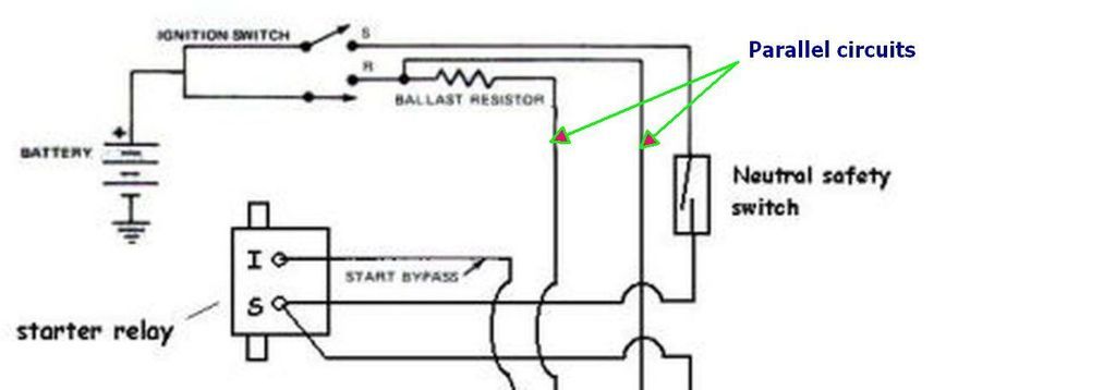
It is my understanding that the red wire to the plug and the pink wire run parallel to each other. Does that mean they both connect to the same terminal on the ignition switch?
On my ignition switch there are two terminals that have two wires coming off of each of them; ST terminal and I2 terminal. The ST terminal has what looks like a red w/blue stripe wire and a red w/white stripe wire. This wire only gets power when cranking the engine and one of them goes to the "S" terminal on the starter solenoid.
The I2 terminal has what looks like a red w/white striped wire and a orange w/green striped wire and it has power with the switch on.
Do you think the red wire and the pink wire plug into the same terminal on the ignition switch, such as the I2 terminal?
Here's what the ignition switch terminals have wires going to it....
BATT = Fat yellow wire--constant power w/key off
BATT = Fat yellow wire--constant power w/ key off
ACC1 = Fat black wire--power w/switch on
ACC2 = Fat orange wire--power w/switch on
ST (2 wires) = red w/blue stripe & red w/white stripe--power only when cranking engine. One goes to "S" terminal on solenoid
P1 = Purple w/white stripe--no power with key on or cranking engine. I believe this is the brake switch wire???
P2 = no wire to this terminal
I1 = white wire--power w/switch on
I2 (2 wires) = red w/white stripe & orange w/ green stripe--power w/switch on
I know I'm getting power to the switch because I've tested for power and other components are getting power when I turn the key on.
It is my understanding that the red wire to the plug and the pink wire run parallel to each other. Does that mean they both connect to the same terminal on the ignition switch?
On my ignition switch there are two terminals that have two wires coming off of each of them; ST terminal and I2 terminal. The ST terminal has what looks like a red w/blue stripe wire and a red w/white stripe wire. This wire only gets power when cranking the engine and one of them goes to the "S" terminal on the starter solenoid.
The I2 terminal has what looks like a red w/white striped wire and a orange w/green striped wire and it has power with the switch on.
Do you think the red wire and the pink wire plug into the same terminal on the ignition switch, such as the I2 terminal?
Here's what the ignition switch terminals have wires going to it....
BATT = Fat yellow wire--constant power w/key off
BATT = Fat yellow wire--constant power w/ key off
ACC1 = Fat black wire--power w/switch on
ACC2 = Fat orange wire--power w/switch on
ST (2 wires) = red w/blue stripe & red w/white stripe--power only when cranking engine. One goes to "S" terminal on solenoid
P1 = Purple w/white stripe--no power with key on or cranking engine. I believe this is the brake switch wire???
P2 = no wire to this terminal
I1 = white wire--power w/switch on
I2 (2 wires) = red w/white stripe & orange w/ green stripe--power w/switch on
#23
07-22-2015, 10:33 AM
It is my understanding that the red wire to the plug and the pink wire run parallel to each other. Does that mean they both connect to the same terminal on the ignition switch?
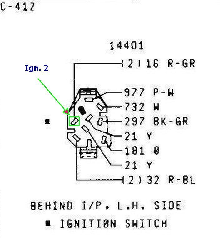
16 (2) Ignition switch to ignition coil “Batt.” Terminal (Red-Green stripe)
977 Brake warning switch to indicator lamp (Purple-White stripe)
732 Distributor electric control feed (White)
297 Ign. SW. (ACCY. Team) to fuse panel Accy. Feed (Black-Green stripe)
21 Battery to Ign. Switch feed (Yellow)
101
21 Battery to Ign. Switch feed (Yellow)
52 Ign. SW. to starter motor relay (Red-Blue stripe)
#25
07-22-2015, 10:59 AM
This is for a 1979 but should be close ..
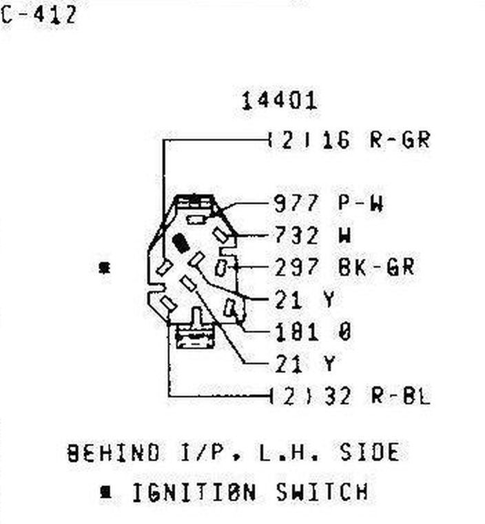
16 (2) Ignition switch to ignition coil �Batt.� Terminal (Red-Green stripe)
977 Brake warning switch to indicator lamp (Purple-White stripe)
732 Distributor electric control feed (White)
297 Ign. SW. (ACCY. Team) to fuse panel Accy. Feed (Black-Green stripe)
21 Battery to Ign. Switch feed (Yellow)
101
21 Battery to Ign. Switch feed (Yellow)
52 Ign. SW. to starter motor relay (Red-Blue stripe)
In electronic speak, is that what "parallel" means; that they connect to the same terminal?
Here's the ignition switch diagram I'm looking at. Scroll down the thread a little way and U'll see the ignition switch I'm referring to. https://www.ford-trucks.com/forums/1059274-1979-f100-ignition-switch-wiring-diagram-positions.html
#27
07-22-2015, 11:18 AM
I will have to look when I get home tonight and report back.
However, when I was opening up the harness last night trying to find where the pink wire splices into, I noticed that the red/green coil wire goes from the distributor plug to the coil. There is a pack of wires (3 or 4) that go from a rectangle plug on the drivers side that comes through the firewall (next to the ignition module plugs) to the distributor plug. Then the coil wire goes from the distributor plug to the coil. Not sure if this info is helpful..maybe I'll unplug this rectangle plug and see if I'm getting any voltage. I assume if the red/green wire isn't getting voltage, then the plug wouldn't be getting voltage either since its the same wire. But who knows.
However, when I was opening up the harness last night trying to find where the pink wire splices into, I noticed that the red/green coil wire goes from the distributor plug to the coil. There is a pack of wires (3 or 4) that go from a rectangle plug on the drivers side that comes through the firewall (next to the ignition module plugs) to the distributor plug. Then the coil wire goes from the distributor plug to the coil. Not sure if this info is helpful..maybe I'll unplug this rectangle plug and see if I'm getting any voltage. I assume if the red/green wire isn't getting voltage, then the plug wouldn't be getting voltage either since its the same wire. But who knows.
#28
07-22-2015, 11:21 AM