
3 VOLTS AT COIL+.....RESISTOR WIRE FAILURE????
#1
 07-18-2015, 02:21 PM


3 VOLTS AT COIL+.....RESISTOR WIRE FAILURE????
I have a 78 F150 that I'm having electrical issues with. I was driving down the road about 3 weeks ago and all of a sudden the truck just shut off!!! After troubleshooting and researching for 3 weeks now I think I've narrowed down the "where" the problem is, but I don't know "what" is causing the problem, which brings me to this site asking for help....
What I found was with the key in the "on" position (engine not running), the wire that goes to the coil + is only reading 3 volts, which is why I assume the truck won't start. From what I understand with all the research I've been doing, there is a "resistor wire" in the wiring harness that reduces voltage to the coil.
My questions are:
1) Tell me if this is correct....At the coil + wire, there should be 12 volts when cranking the motor, about 7 volts with the key in the "on" position, and about 9 volts with the engine running?
2) If the resistor wire went bad, would it cause this low voltage problem I'm having with the coil + wire with the key in the "on" position (3 volts instead 7 volts)?
If the resistor wire is not the problem, can you tell me why I'm not getting hardly any voltage at this wire with the key in the "on" position? The ignition switch is brand new (I replaced it thinking this was the problem). I have a MSD 6A ignition box and an Auto Meter tach hooked up and it won't even turn them on when I turn the switch to the "on" position because of lack of voltage in the factory red/green coil + wire.
Any advice or thoughts is greatly appreciated. Thanks...
#2
07-18-2015, 02:27 PM

#3
07-18-2015, 02:42 PM
I haven't open up the wiring harness under the dash yet to inspect the resistor wire, but before I do I'd like to know what the symptoms of a bad resistor wire would be? Would it cause the little to no voltage in this ignition/coil wire that I'm experiencing?
#4
07-18-2015, 03:10 PM
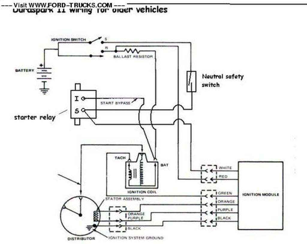
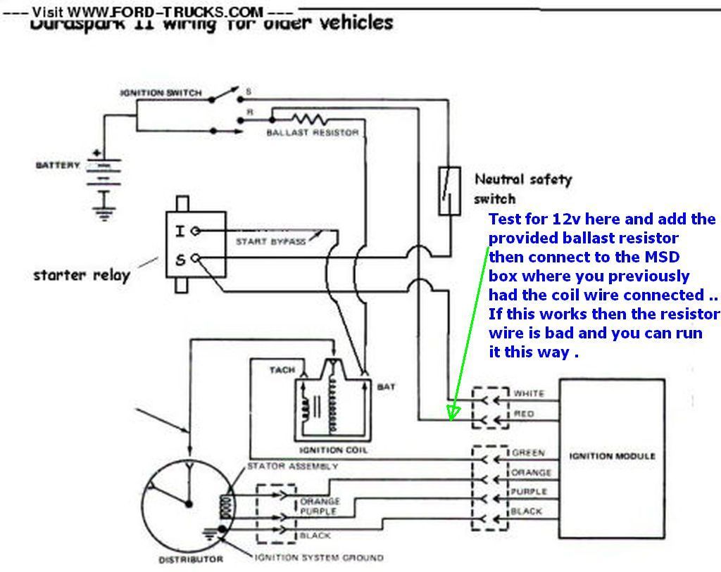
The resistor wire should be 1.3-1.4Ω resistance between the ignition switch and the coil. This will drop the voltage when the engine is running to ~9V instead of 12. A bypass wire from the starter solenoid "I" terminal provides full voltage during cranking.
If the resistor wire has broken or partially melted but is still making a little bit of contact somewhere, it's possible you could have much higher resistance and be getting only around 3V through it. Or if it's entirely broken/burned up, you should get no voltage at all.
It sounds like the resistor wire is probably your culprit. You can buy a replacement for it:
https://www.npdlink.com/store/produc...401-50000.html
If you replace it, check to be sure nothing but the coil is powered through it - often times, they'll burn up because someone decided to power an electric choke or something else off that wire and it pulls too much current through it.
You should check first, however, to be sure you have 12V at the ignition switch.
#5
07-18-2015, 03:42 PM
The resistor wire should be 1.3-1.4Ω resistance between the ignition switch and the coil. This will drop the voltage when the engine is running to ~9V instead of 12. A bypass wire from the starter solenoid "I" terminal provides full voltage during cranking.
If the resistor wire has broken or partially melted but is still making a little bit of contact somewhere, it's possible you could have much higher resistance and be getting only around 3V through it. Or if it's entirely broken/burned up, you should get no voltage at all.
It sounds like the resistor wire is probably your culprit. You can buy a replacement for it:
https://www.npdlink.com/store/produc...401-50000.html
If you replace it, check to be sure nothing but the coil is powered through it - often times, they'll burn up because someone decided to power an electric choke or something else off that wire and it pulls too much current through it.
You should check first, however, to be sure you have 12V at the ignition switch.
If the resistor wire has broken or partially melted but is still making a little bit of contact somewhere, it's possible you could have much higher resistance and be getting only around 3V through it. Or if it's entirely broken/burned up, you should get no voltage at all.
It sounds like the resistor wire is probably your culprit. You can buy a replacement for it:
https://www.npdlink.com/store/produc...401-50000.html
If you replace it, check to be sure nothing but the coil is powered through it - often times, they'll burn up because someone decided to power an electric choke or something else off that wire and it pulls too much current through it.
You should check first, however, to be sure you have 12V at the ignition switch.
I will definitely make sure there is nothing running off this wire other than the coil. But with that said, let me ask this....This wire is considered a "switched" wire that provides power to things like the MSD ignition box when the switch it turned on. The instructions instruct to use this factory coil wire to provide "switched" power to the MSD Box. Let me clarify that I understand you correctly....The MSD box is ok to power with this factory coil wire, but NOTHING else should be running off this wire? If another component needs "switched" power, it's ok to splice into a "switched" wire coming off the ignition switch as long as it's not the "resistor" wire?? Is that correct????
If I do have a bad resistor wire and need to replace it, can you explain the details regarding the splice itself? I've heard guys say that you have to splice the exact length of wire using special "appliance" connectors instead of standard connectors, etc....can you elaborate on this? Or would it be easier and better to use a ballast resistor instead of trying to splice in a new resistor wire? I was supplied a new ballast resistor with my MSD ignition box that seems to be the correct resistance/ohms that my truck requires. If the length of resistor wire and connectors are extremely important to get correct, should I just use this instead of attempting to splice in a new resistor wire? What would you do?

#7
07-18-2015, 05:03 PM
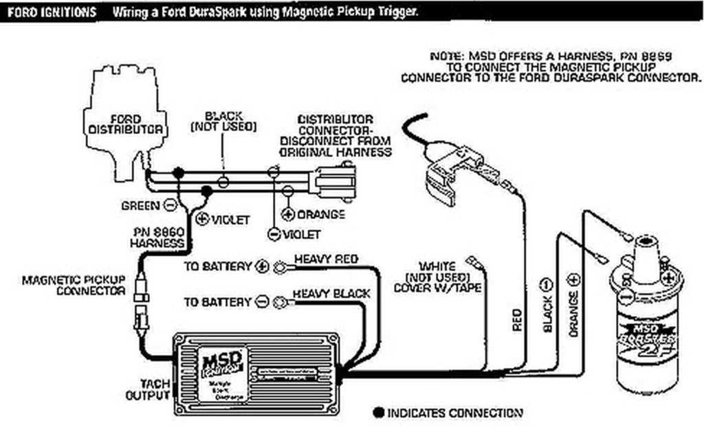
Redroad, I disconnected the red/white connector at the duraspark II an wired the MSD like this....(not sure how to post a picture like you did, so here's the link to the picture)
https://www.google.com/search?q=msd+...FzwgoP4G4QM%3A
https://www.google.com/search?q=msd+...FzwgoP4G4QM%3A
Trending Topics
#8
07-18-2015, 05:31 PM

#9
07-18-2015, 05:47 PM
Redroad, I'll try your suggestion...So if I connect it up this way using the ballast resistor, what do I do with the existing resistance wire? Do I disconnect it by cutting it out?...
Also, just for FYI...I've been driving the truck like this for a couple years and all of a sudden it just shut off. This is not a new setup. It's been functioning fine until now. Not sure if that makes a difference in the wiring setup....
Also, just for FYI...I've been driving the truck like this for a couple years and all of a sudden it just shut off. This is not a new setup. It's been functioning fine until now. Not sure if that makes a difference in the wiring setup....
#10
07-18-2015, 05:52 PM

#11
07-18-2015, 06:09 PM
Sounds good. I will try that and see what happens. I won't be able to get to do this until Monday at the soonest. We're right in the process of getting ready to move. So I'll report back sometime this week with results. Thanks for your help....
#12
07-18-2015, 06:13 PM
Sounds good. I will try that and see what happens. I won't be able to get to do this until Monday at the soonest. We're right in the process of getting ready to move. So I'll report back sometime this week with results. Thanks for your help....


#13
07-18-2015, 06:26 PM
[QUOTE=redroad;15510689]In The abandoned Duraspark II module harness try the following .. Keep in mind keeping the wire as short as possible is more desirable in this instance ..
Redroad, after reviewing your diagram again, I had a question....When I cut the resistor wire, where do I cut it? Before the splice (on the ignition switch side of the splice) or after the splice (resistor wire side of the splice)??? This may seem like a dumb question, but I need to be clear on where to make this cut. I'm guessing to cut it after the splice (on the resistor wire side of the splice). Is this correct?
Redroad, after reviewing your diagram again, I had a question....When I cut the resistor wire, where do I cut it? Before the splice (on the ignition switch side of the splice) or after the splice (resistor wire side of the splice)??? This may seem like a dumb question, but I need to be clear on where to make this cut. I'm guessing to cut it after the splice (on the resistor wire side of the splice). Is this correct?
#14
07-18-2015, 06:37 PM
When you brought the wire from the coil shoe to your msd box you made a connection just cut it there and wire nut it and zip tie it to keep it from flopping around .. Then take the wire you grabbed from the old DurasparkII module harness and put the provided ballast resistor on and run a wire to the MSD box's lighter gauge red wire .. If you need further clarification just post back
#15
07-18-2015, 06:48 PM
When you brought the wire from the coil shoe to your msd box you made a connection just cut it there and wire nut it and zip tie it to keep it from flopping around .. Then take the wire you grabbed from the old DurasparkII module harness and put the provided ballast resistor on and run a wire to the MSD box's lighter gauge red wire .. If you need further clarification just post back