When you click on links to various merchants on this site and make a purchase, this can result in this site earning a commission. Affiliate programs and affiliations include, but are not limited to, the eBay Partner Network.
I'm going to try this again to see if I can include the pictures in the post:
F1 FENDER RUST REPAIR AND PATCH PANEL FORMING
Introduction:
Gary (jgp 1952 on FTE) asked if I would look over and give him some advice and instruction on repairing some �minor� rust issues on his recent F1 acquisition. The PO didn't like the �manure spreader� front on the 52, so had replaced the doghouse (front clip) with one from a 48 �monkey face�. The truck had been stripped down to the bare frame, then the entire truck had been sandblasted and epoxy primed. Upon first examination the sheet metal looked pretty solid with little obvious rust thru. A closer look at the usual trouble spots inside and out however showed some signs of previous repairs, bondo and rust hidden under the primer as well as the front fenders had a fairly hard life (or had been attacked with a ball peen hammer) The entire fenders felt like an overstuffed bag of marbles, there didn't seem to be a really flat smooth area anywhere. Examining the panel edges revealed a number of cracks, and signs that several more had been roughly welded over. The upper and lower fenders, front valance and grill were still bolted together with the OEM bolts and had been blasted and primed as a unit.
I had been wanting to try my hand at restoring a set of F1 fenders. Since rust out is quite common and no one offers repair panels, new patch panels would need to be formed. I wanted to do a write up on forming panels using common materials and what tools anyone should have available in their shop if they want to do their own body work.
I had already posted my MIG welding tutorial on FTE: https://www.ford-trucks.com/forums/1...-practice.html so this would be an opportunity to show the techniques in use, and pass on some of my knowledge and experience to others before it is gone forever. I agreed to help and teach Gary the �simple magic� of metal work, as long as he would do the majority of the dirty, tedious, busy work stuff and let me use his truck as the model for this article. I would demonstrate/teach the techniques to him on one side and let him practice his new skills on the other side.
Since we only get to spend an average of about 6 hours a week working together, this is going to be a fairly long project, so I will be adding to this topic as we progress. So let's get started bumping, bending and filling metal.
Phase 1: Assessing the work needed and collecting the necessary tools and materials.
We would be working on the front fenders, so the first thing I asked Gary to do is fully disassemble the front clip, then strip the driver side upper and lower fender of as much of the primer as possible, inside and out. I suggested using a 3M clean and strip disk available at the local big box DIY stores. Once most of the paint was removed we could really see what we had to work with. Since all he had in his shop was a basic set of Harbor Freight �clubs and rocks� (their version of body hammers and dollys) I also showed him some of the hammers and dollys I use most often and what makes them a superior tool to work with, and suggested he surf ebay and be picking up a few used but professional quality tools. Since we would start by working in my shop he would also see what I had and how I used them. He brought over both fenders so we could compare the best parts of each, as well as the front grill and lower valance panel.
He had stripped most of the paint on the drivers side fender sections, which revealed a lot of painted over rust, bondo, and previously done (poorly) repairs that I'll come back to as we repair them properly. A number of additional edge cracks and dents were exposed and the very uneven dented surfaces was revealed to be worse than originally thought (lesson: dark primer will hide a lot of sins, so be very careful when buying anything that has been covered in primer.) It quickly became obvious a number of patch panels would need to be made so a stock of new sheet metal would be needed. I found a national steel supplier online that carried 19 ga �aluminum killed� (also called �deep drawing�) cold rolled steel in 4x8' sheets, the ideal material for forming patch panels. They could ship, but they also had a warehouse in Greensboro, about 1.5 hrs from us. It was pricey in single sheets but the price dropped dramatically the more you bought. They would also shear the sheets in � for a small charge. Gary ordered 2 sheets sheared and his wife drove to the warehouse and picked it up on her day off.
Gary also requested that we fill the frame notches in the bottom of the fenders since he like the smooth bumperless look and the PO had already cut off the front frame horns. There was rust damage over and into the inner doubler that surrounded the notches, so it was actually easier to fill them than reuse/remake the doubler.
Phase 2: removing damaged metal, developing a pattern for a wood hammer form, shaping and installing first patch
A repair order plan was decided on, the rusted fender sections that needed to be removed were marked, and the work began. See pictures:
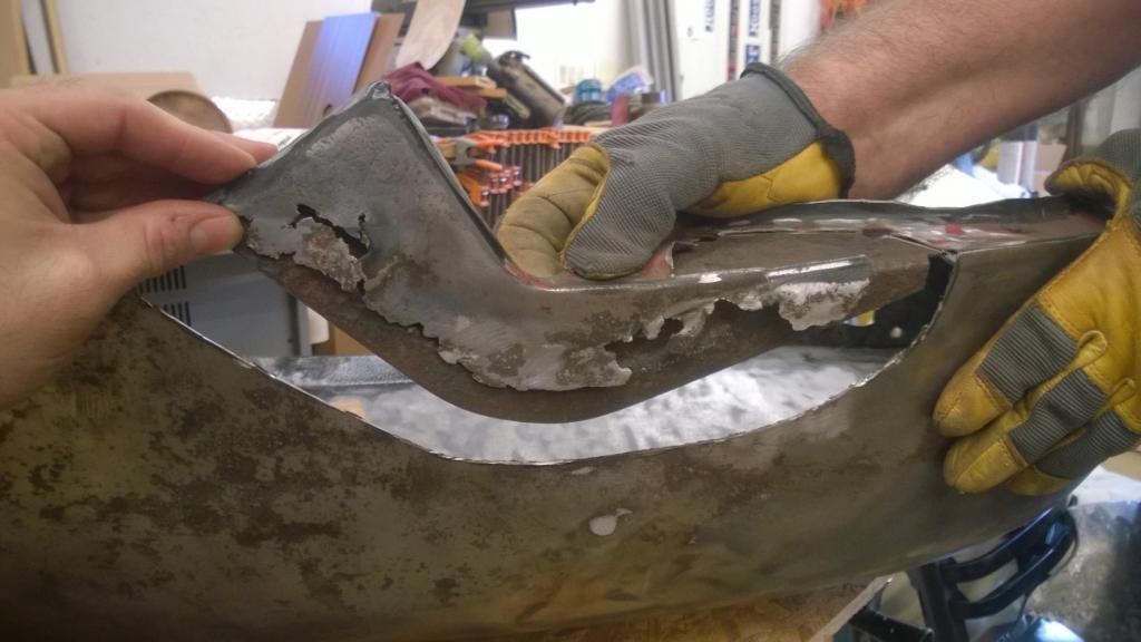
(Picture FRR01)
Rust out in upper fender over doubler partially cut away.
(Pic FRR02)
Spot welds drilled out, rest of face material removed from doubler. Note that still solid formed rear edge was retained since it indexes lower section and holds doubler in place.
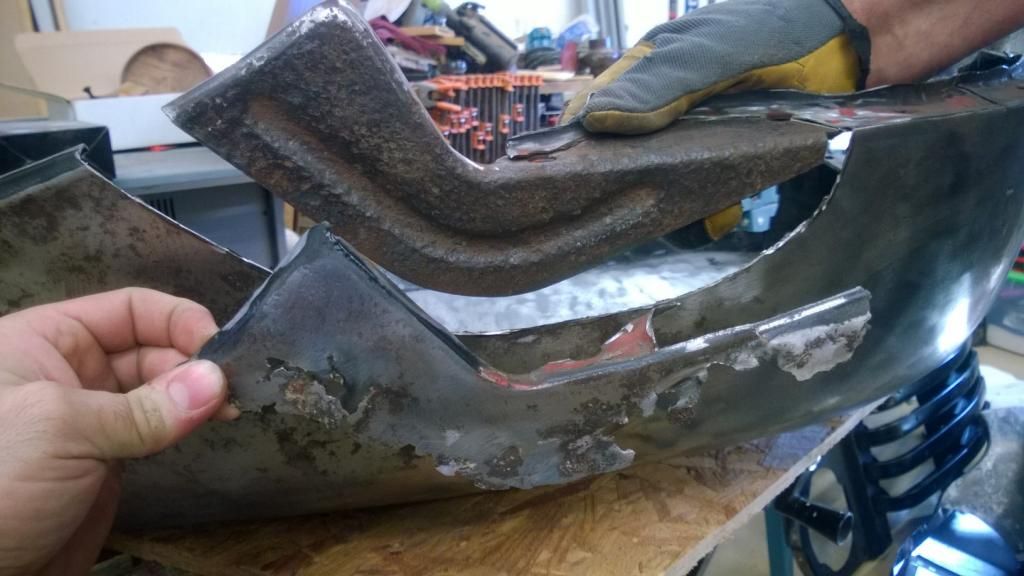
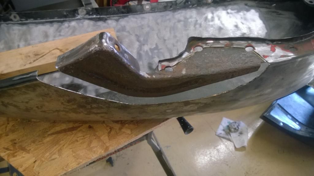
(Pic FRR03)
All rust damaged metal removed back to full solid metal. Note that curved cuts were used to avoid corners in seam on face of panel. All loose rust removed from doubler, treated with rust reformer and then given heavy coat of weld thru zinc rich primer (NAPA products, not shown). Had doubler been rusted through or damaged a new doubler would have been made from 2 pieces of the appropriate thickness metal. Here it was sound enough to treat and reuse.
Attempting to bolt/clamp the upper and lower fender back together revealed that removing the section of corroded metal released tensions from dents and cracks so the two parts no longer wanted to go back together, and the edges waved in and out. I thought I might be able to make a pattern off the other fender, but in attempting to do so it became obvious Ford had not made the two fenders match well enough to interchange, so each side would need to be individually repaired/fitted. I decided it would be necessary to take out most of the dents and repair the open cracks before proceeding any further with making the patch pattern/patch so the fender 1/2s had the same matching (smooth) contours. Altho it's surface was quite bumpy, the lower section was smaller, had not yet been cut so it was decided to adjust that piece first then fit the upper section patch to it along the flanges. I brought out my shrinking disk and I showed Gary how to use it to smooth out the �bag of marbles� dents that covered the panel. I also welded a couple cracks. (More on using the shrinking disk later. One crack that was thru a bolt hole and had sprung open required pulling it back together with a strap wrapped around the panel and I added a doubler to the under side of the flange to reinforce it and prevent it from re-cracking. I used a hammer and several different shaped dollys as well as a piece of 5/8� rod clamped inside to straighten the fender opening roll and smooth the contour at the bottom where it looked like it had been bent under by hitting a curb more than a few times.
Putting the pieces together again it was easier to see where the upper fender was distorted and required adjusting. I took out several shallow but good sized dents with a plastic torpedo mallet and rubber dolly (hockey puck!) I wasn't too concerned about putting in small bumps with the mallet, they would be easy to smooth with the shrinking disk, but it was impressive how bumping up a 3� diameter shallow dent 8-12� away would cause an edge to move back into place and the entire fender to come back into shape. Once I had the two pieces fitting well, I clamped a short length of rod into the wheel arch roll and to the doubler to hold it while I made my pattern from poster board.
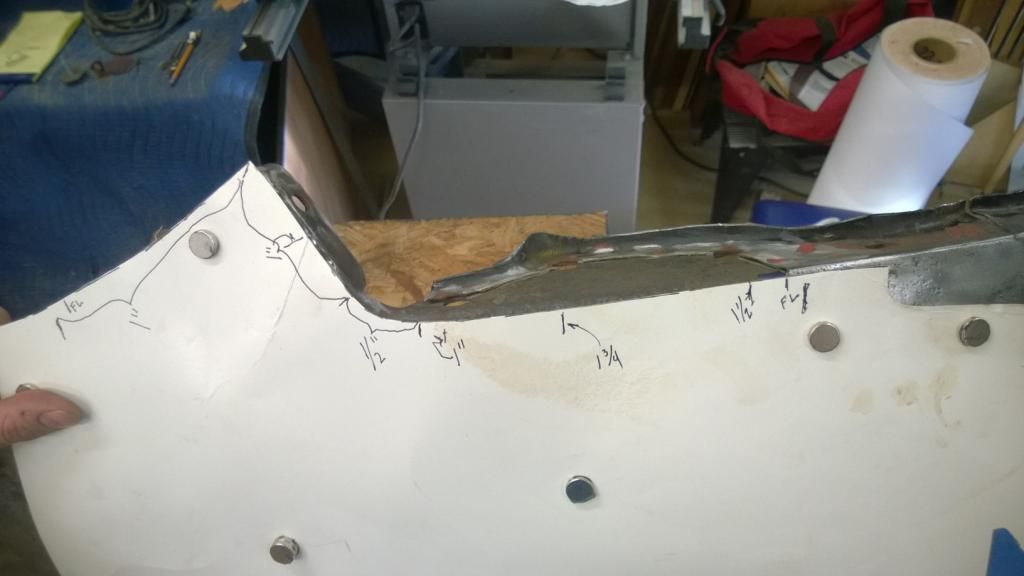
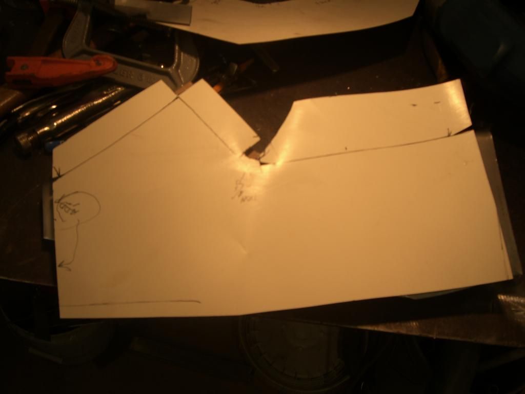
(Pic FRR04)
I held a piece of poster board tightly in place with several small but powerful rare earth button magnets while I traced the patch edge. I carefully cut it out and checked it, then marked the flange widths that would need to be bent.
(Pic FRR05)
That pattern was traced onto another piece of poster board adding the flange widths. The weld seam portion at the bottom was left a couple inches oversized. This pattern was used to cut my metal blank.
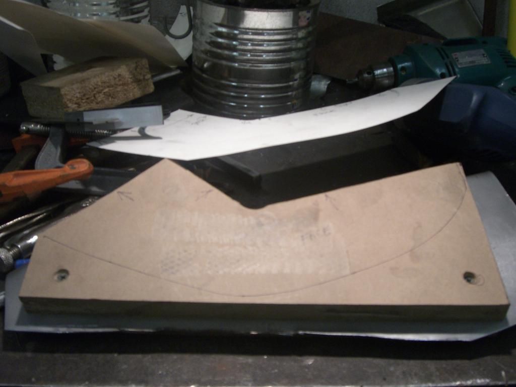
Two identical pieces of 3/4� MDF board were cut then drilled/screwed together in the waste areas left in the previous step. The first pattern (without the flanges) was trimmed the thickness of the metal along all the edges that will have flanges then traced onto the MDF. I cut along the fold lines with my bandsaw while the 2 pieces of MDF were screwed together. I then removed the screws, sandwiched the metal blank between the two MDF forms. Drilled matching screw holes in the metal and screwed the assembly together.
(PicFRR06)
MDF and metal blank sandwich. Note indication of the weld seam line drawn on MDF so the screws would be placed outside in the future trim waste.
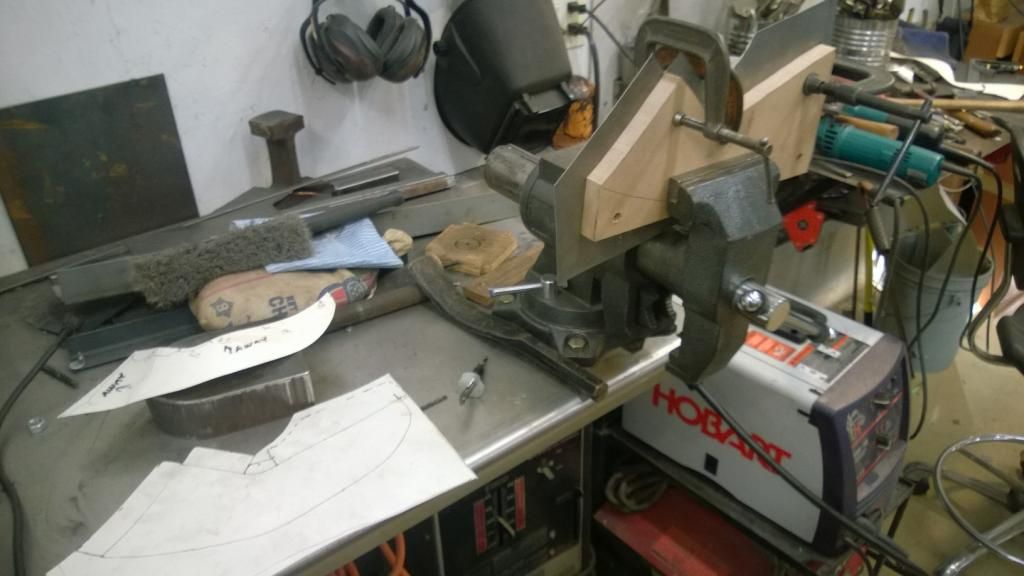
(Pic FRR07)
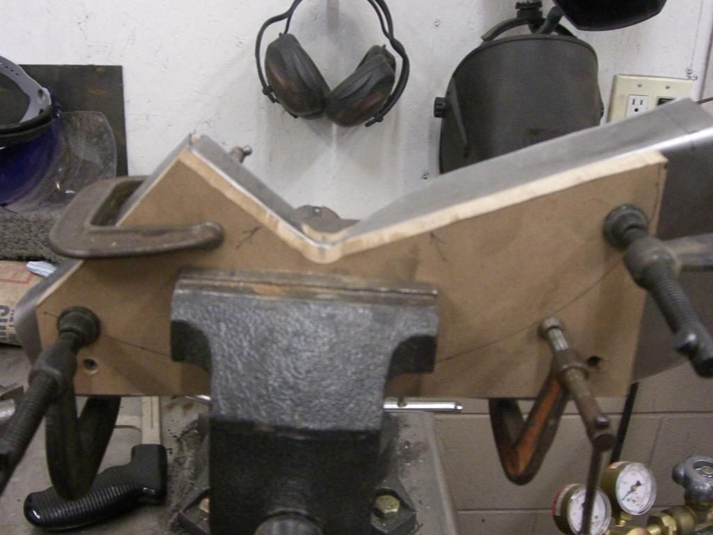
Form placed in bench vise and several heavy clamps added to keep sandwich from opening while bending. Still more clamps were added after picture was taken before bending You can't use too many clamps!.
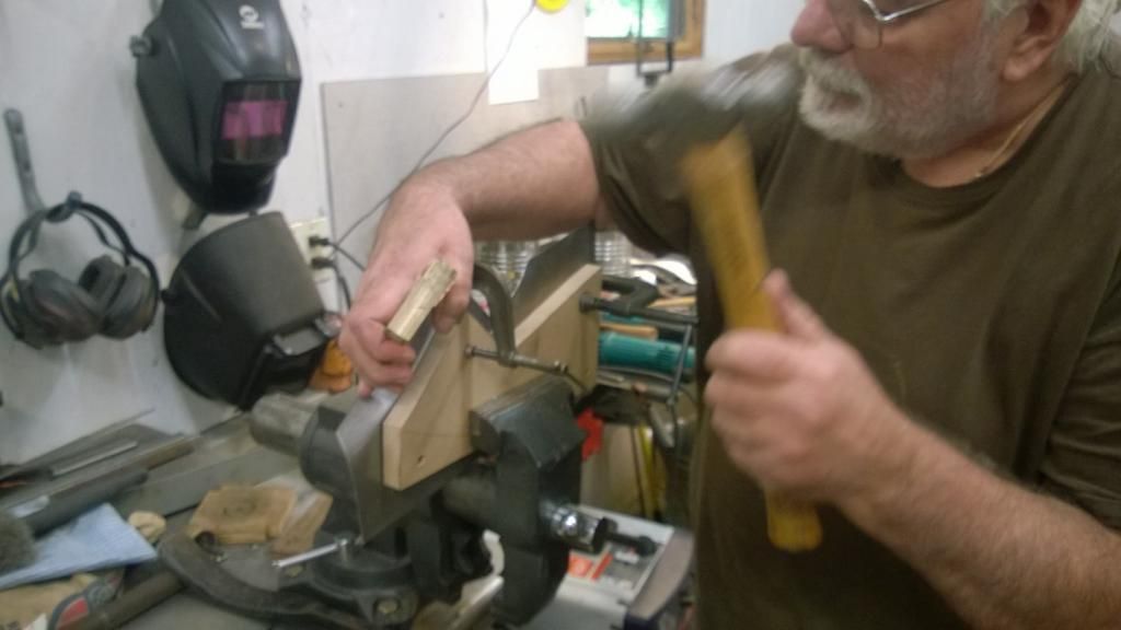
(Pic FRR08)
A wood �punch� and hammer is used to bend the flanges in several stages of about 10 degrees each time around. This is 3<sup>rd</sup> pass over this section. Clamp removed for clarity, replaced before continuing.
(Pic FRR09)
Flange fully bent. Note that bend on left is a shallow curve to match wheel arch curve, flange was formed around tight curve by using ball end of ball peen hammer as punch and second hammer (flange width reduced to 3/8� in that section to ease forming same as Ford did). By working slowly it is possible to form complex shapes using a hammer form system like this.
(Pic FRR10)
Patch was clamped in place scribed and slowly trimmed until t fit perfectly with no gap along seam. Note that horizontal flange on right was trimmed to 3/4� wide, since it needed to have a shallow curve left to right, I used my shrinker on that flange to curve it. A filler piece will be welded in later.
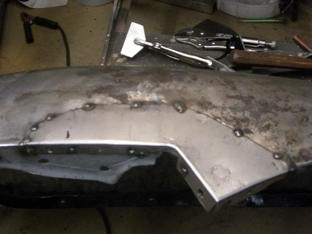
(Pic FRR11)
Holes drilled in flanges for plug welds. Seam tack welded.
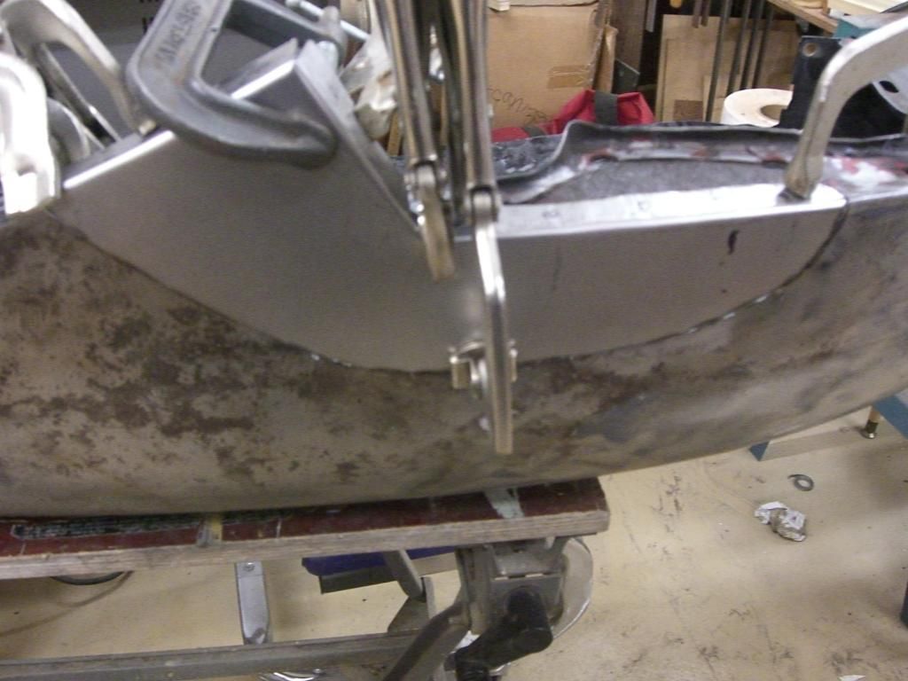
(Pic FRR12)
Patch with lower fender bolted in place before final welding. Note fit of patch between upper and lower panel, along seam and continuous curve along edge of wheel arch.
Next installment: Front of lower fender repaired, frame opening filled.
I will be using the shrinker quite a lot when I make the patch for the bottom rear of the fender, so stay tuned. Same with the shrinking disk when we go back to smoothing the humps and bumps in the fenders. I want to get the patches welded in completely first so if the seams need stretching they can be smoothed in at the same time.
Patch looks great! Curious why you didn't media blast the rusty inner piece while exposed? Or the whole fender?
Keep up the good work.
No media blaster.
I have a small cabinet, but not near large enough for a fender. The doubler looks rough in the picture, but it was abrasive brush cleaned and the dark color is due to the rust converter treament. It was given a heavy coat of weld thru primer (not shown) before the patch was attached. The edges will be given a coat of seam sealer before the fender is painted. The entire truck had been blasted previously, we just sanded off the primer coat to be able to assess what was underneath. The doubler was still plenty sturdy/near original thickness, so it was reused. Had it been weakened or rusted thru it would have been replaced as was/will be done with some doublers elsewhere. It took 65+ years to get to this point totally unprotected, so it should live plenty long enough from here with what we did. By the time it rusts out again, we will be 3-D printing replacement fenders in the corner of the garage!
Remember I am trying to demonstrate that a lot of body work/rust repair can be done in the home shop without years of experience, investing in10s of thousands of dollars in major tools or the availability of ready made patch panels. If patch panels or reasonably priced NOS or repro fenders were available for the F1, I would have recommended using them instead. Used fenders any better than these are scarce (at least in this part of the country) and expensive, most need at least as much work to restore as these.
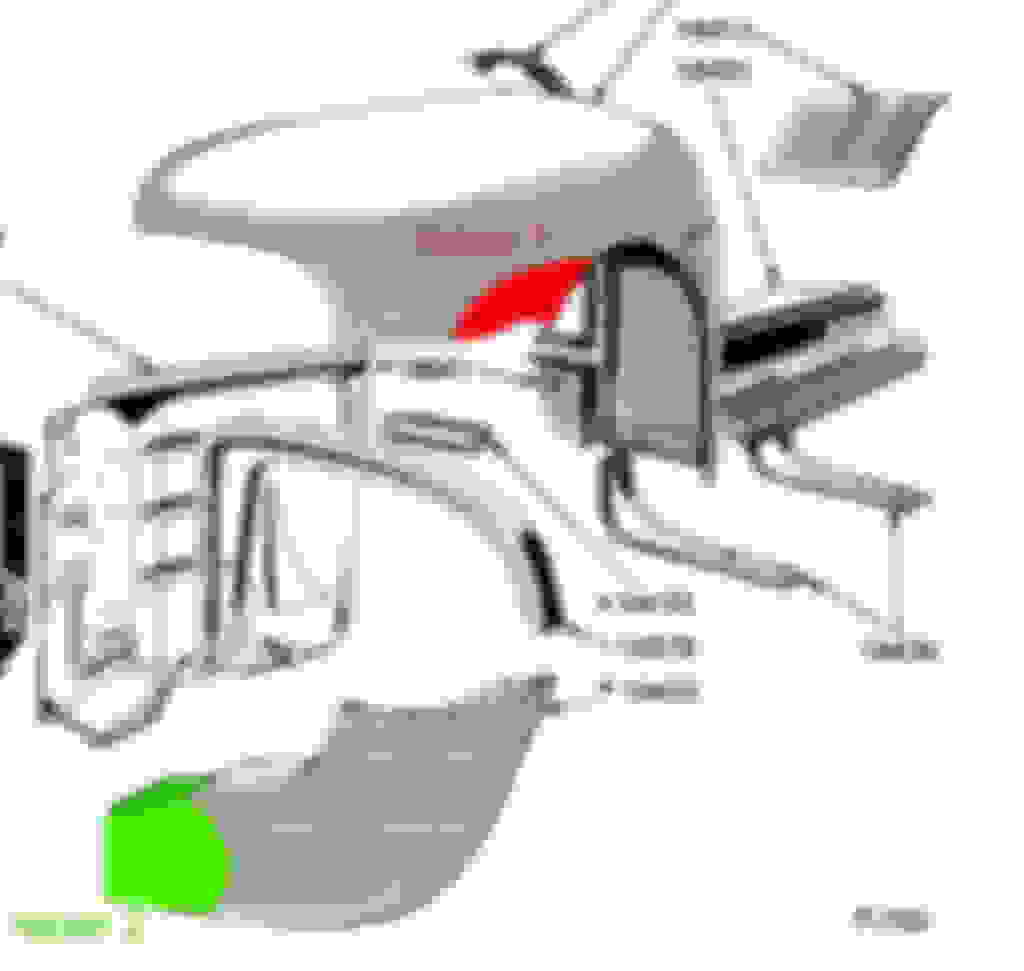
Phase 3: fender lower front and frame opening (repair 2 green in drawing) .
Next rust damaged area to be dealt with is the lower front of the fender along side the frame opening and below the headlight panel. There is a large complex doubler in this area, and it is open to the wheel, so a lot of water, dirt, and road chemicals/debris is thrown up into this portion of the fenders on the �monkey face� F1s. The doubler stiffens 2 sides of the open bottom U frame horn opening and supports the headlight panel as well as connecting to the lower grill valance. It also stiffens the front of the lower fender section. On this fender lower section the surface sheet metal was rusted thru over the doubler on the face of the panel along the vertical portion of the frame opening and on the horizontal surface from the face to the headlight panel. The section of the doubler that reinforced the outside vertical side of the frame horn opening was also rusted thru and heavily deteriorated. Since the PO of Gary's truck had bobbed the frame horns and Gary liked the appearance of the openings filled with no bumper we decided to fill the opening at the same time to avoid extra face seams. Since this area would be all one piece and bolted to the lower valance it was decided to remove the heavily corroded section of the doubler. The rest of the doubler would be reused to strengthen the area under the headlight and maintain the fit and shape. The repair patch that would be created would be made in two pieces, it would be very difficult to form a very wide curved flange under the headlight (darker green portion in drawing) without getting a lot of distortion in the face of the panel. This is not a portion that gets a lot of scrutiny since the headlight bucket masks most of it, and is a compound curve backed by the doubler, any weld distortion could be easily dealt with.The face metal was trimmed to solid metal along a curved line, and the spot welds attaching the doubler were drilled out and the surface metal removed from it. The heavily corroded and no longer needed portion was cut away. Had the frame opening to remain, a new section of doubler would have been formed and attached. From here on the forming of the patch panel and installation was done similarly to the previous repair except where noted.
FRR201
Heavily rusted section of doubler that was removed. The frame horn opening was to the lower right. The bulging rusted out face metal over it had been filled with bondo and primed over.
FR201a
Remaining portion of doubler with spot welds drilled out and rusted thru outer sheet metal stripped off, being fitted back in place so an accurate patch pattern can be made. Note again metal has been cut away along a curve. Curved seams are shorter and don't concentrate heat/shrinkage in a small area like a corner. Much easier to stretch seam if needed and requires less metal finishing.
FRR202
The 2 sections of fender, front grill/headlight panel, remaining doubler and lower valance were all bolted/clamped together and a posterboard pattern was traced like in Repair1. An MDF hammer form and oversized sheet metal blank sandwich was created, and clamped together in the vise.
Note: the flange that formed the bottom edge of the fender was not a sharp bend, but transitioned from a � roll (�J� shape) towards the wheel arch to an angled narrow flange at the valance. To shape this edge The face piece of MDF (the side facing me in the picture) was cut back 1/4� shorter than the rear piece. I marked the rear piece along this new edge and drew another line 1/4� on the adjacent edge of the rear MDF piece of the form. I used the two lines as a guide and with a small palm sander I sanded the sharp corner to a 1/4� � round in this edge. Folding the metal over this edge made this flange bend have a rounded curved shape. This is the side running bottom left to top right under the two clamps in the picture.
I then determined how wide the remaining portion of the flange needed to be to complete the �J� shape and trimmed to width, Clamped a piece of 5/8� steel rod to the patch and used a weighted plastic mallet to bend the remainder of the flange around the rod into a perfect matching �J�. There are more areas with that �J� shape edge where straightening or repair need to be done, so I am going to bend some 5/8� and 1/2� rod into curved and straight forming stakes and weld handles to them. I'll take pictures of what they look like and how I use them in repair 3.
FRR203 The curved section under the headlight was a originally a wide curved flange over the doubler that would have required excessive metal shrinking to make in one piece so it was decided to make this portion in 2 pieces. The portion of the blank that would form the front of the flange was cut back to 1/2� wide in this area. The end of a wood punch was sanded to a matching curve to fold the flange over with. By bending it slowly with several passes it folded down flat. A curved universal dolly was used like a hammer to tap the flange smooth and tighten the bend to where a light pass with a � round file trued up the surface and edge. A light pass with a flat file straightened the edge where the 2 pieces will be seamed. Note: you can see the start of the curved J bend edge just below the short straight flange.
FRR204
The folded but oversized patch was clamped in place and check for fit. The seam was scribed on the back with a sharp scribe. Cut just outside the scribe line and carefully trim to a perfectly tight accurate fit.
HINT: to make scribed lines easier to see. Color a wide path where the scribe will go with a permanent marker before scribing. The scribe mark will stand out as a bright silver line through the blackened metal. The marker will quickly burn away without any residue when you weld the seam.
FRR205
View from inside of fender of patch being fitted. Note that doubler has been bolted/clamped into place for fitting.
After cutting the patch along seam it became obvious the fender was not flat (seldom is a panel perfectly flat. A bowed or bulged panel will be much stiffer without tendency to �oilcan�) but it had a slight bow top to bottom along the seam. A very shallow curved dolly and large diameter slightly crowned face body hammer was used to place a couple rows of slightly overlapping ON DOLLY taps from top to bottom near the seam edge to very gently stretch the panel so it will bow up. Take your time and recheck fit after each row. At first it will seem like you aren't doing anything, but after doing several rows, checking the panel with a ruler will show it is no longer flat. Be patient avoid the temptation to whack at it. HINT: If you don't know the difference between on dolly and off dolly hammering, and why/where to use each, stop everything and order a copy of Ron Covell's outstanding DVD: Basic Techniques for Working with Steel. Ron Covell Creative Metalworking Workshops
FRR206
The patch has been trimmed to fit and tack welded to the face of the lower fender panel. Note the small overlapping hammer marks where the on dolly stretching was done and may be able to see the shallow bulge in the patch to match the bulge along the seam. Had a more pronounced bulge been needed, I would have used a torpedo mallet and sandbag to create the bulge and smoothed out any dimples by planishing over a dolly or shrinking them out with the shrinking disk depending if I wanted more or less bulge. A short length of 5/8� rod was clamped into the J bend across the seam to hold that edge of the patch in alignment while tacking.
FRR207
The tacked patch from the inside. Note the Magic marker band used to make the scribe line easily visible. I use a machinist scribe, but a sharp ice pick, awl, knife point, or the short scribe usually built into a sliding adjustable square (Aha! That's what that little round **** is in the center of the sliding portion. Unscrew it and pull it out!) or anything sharp that will mark right into the corner will work. Don't use a pencil or pen, or your patch will come out undersize. The doubler has been removed here. The J bend edge transitioning to a narrow flange is at the top in the picture, will be refined and adjusted later.
FRR208
Here I have turned the fender panel upright after unbolting the grill and valance and tacking the doubler to the lower fender panel. A filler patch was then formed from sheetmetal to finish off the wide flange over the doubler. A strip of metal was cut and a 3/4� flange was bent on one end using my little 30� bench brake. It was then bent over a large round dolly (a 6� section of a welding tank I picked up at the metals recycling yard.) This strip needs to be tapered in shape, so it was set in place and the shape marked then cut and sanded to fit. It was deliberately left a little long on the left side, the overhang will be trimmed off after welding it in place. Note the full penetration of the tacks securing the doubler done from the other side near the top of the picture, as well as the close fitting seams around the filler patch.
FRR209
After tacking the flange filler piece all around the fender panel was once again bolted to the grill and valance. The doubler was plug welded to the filler from this side, and the welds as well as the protruding filler edge were ground smooth. A 1� x 1� vertical doubler was bent and welded into place then a second bolt hole was drilled thru the valance, new filler patch and the new doubler (bolt just below clamp) to secure everything.
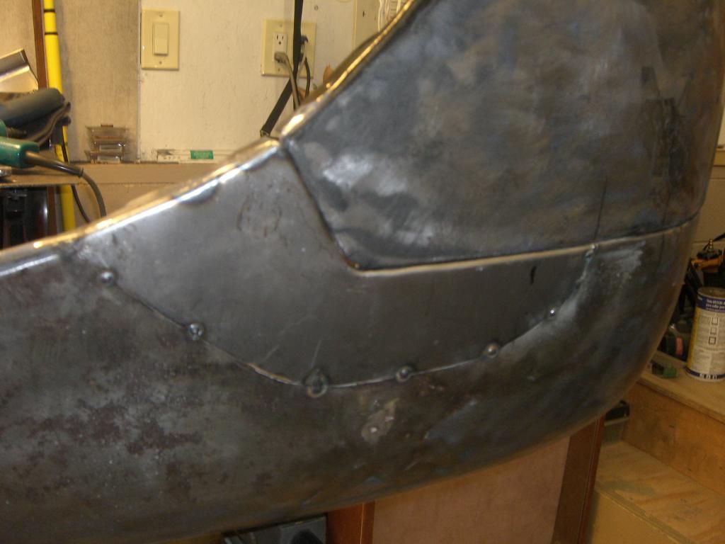
FRR210
Here is the completed lower front fender rust repair and frame hole fill ready to be finish welded and metal finished. Note the smooth line along the rolled fender bottom edge, and along the S curve below the headlight panel as well as the fit at the valance. The bulge in the patch and lower fender match along the seam and blend to flat at the valance.
Next installment: Front fender at running board repair
Well the site software won't let me edit the second section now, so it'll have to be what it is, formatting errors etc. Should still be understandable if not fire away with questions/comments.
 12-02-2014, 11:36 AM