Bye Bye Front Drums
#316
 01-29-2015, 02:12 PM

Hotshot
They said they have all the parts, individually (of what's supposed to be together as a set).
Bearings are $12.50 ea. Seals are $10.00 ea. Bearing collars are $4.00 ea. This means the sets have been broken up.
I told them I need (2) bearings and (2) collars.
I suspect axle seal rubber technology has probably improved since 1969 and I don't think I want rubber axle seals that old, that have probably been sitting in a (likely) non-climate controlled warehouse. I have new seals anyway.
They're supposed to get back with me, to confirm that the bearings and collars are on hand.
#317
01-29-2015, 04:16 PM
The bearings are NOT $12.50 ea. They're $17.50 ea. --still not a bad price. The bad news, however, is they have (2) bearings but only (1) bearing retainer/collar for these bearings. So, again, the other axle bearing is useless without the retaining collar for it.
Seals, whatever they're for, should always be coated with whatever type of fluid they will be retaining, prior to the object being installed that the seal will be riding on. In other words, they should not initially be installed with the rubber portion being dry, before the seal has a chance to break in. Dry seals will fail sooner than ones that were coated, prior to component installation into to them.
#318
01-29-2015, 05:05 PM
Hotshot
[QUOTE=ultraranger;15040187]Sad Trombone (aka, 'loser sound effect') time again.
The bearings are NOT $12.50 ea. They're $17.50 ea. --still not a bad price. The bad news, however, is they have (2) bearings but only (1) bearing retainer/collar for these bearings. So, again, the other axle bearing is useless without the retaining collar for it./QUOTE]
Yeah. I know. I talked with him just a bit ago buying some C9ZZ10094A 's off them For my supercharger belt's idler pulleys. C9ZZ10094A was the front bearing in old style small case Ford alternator. Pretty sure GM's also. But this is also the bearing used in a gazzion v-belt and serp belt idler pulleys.
They show 2 of the C9AZ1180A on the locator???? I'll list more here in a minute.
#319
01-29-2015, 05:28 PM
Hotshot
C9AZ1180A
The Lincoln/mercury Old Parts Store...shows 1...727-445-7551.
Green Sales.....................................shows 2...800-543-4959.
Dennis Carpenter Ford.......................shows 3...800-476-9653.
NOS Parts Warehouse........................shows 34..888-727-0418.
Miller Obsolete Parts..........................shows 5....607-722-5371.
NOS only..........................................show s 3....800-667-6659.
RPN Parts.........................................show s 2...888-864-9305.
Haven Ford.......................................shows 2...620-465-2252.
#320
01-29-2015, 06:51 PM
[QUOTE=JEFFFAFA;15040281]
I guess it's a good thing the s'charger/alternator bearing you need doesn't require a bearing collar, 'cause they'd probably tell you they ain't got it.
Then YOU'D be hearing, wah wah wah wahhhhh!
Sad Trombone (aka, 'loser sound effect') time again.
The bearings are NOT $12.50 ea. They're $17.50 ea. --still not a bad price. The bad news, however, is they have (2) bearings but only (1) bearing retainer/collar for these bearings. So, again, the other axle bearing is useless without the retaining collar for it./QUOTE]
Yeah. I know. I talked with him just a bit ago buying some C9ZZ10094A 's off them For my supercharger belt's idler pulleys. C9ZZ10094A was the front bearing in old style small case Ford alternator. Pretty sure GM's also. But this is also the bearing used in a gazzion v-belt and serp belt idler pulleys.
They show 2 of the C9AZ1180A on the locator???? I'll list more here in a minute.
Then YOU'D be hearing, wah wah wah wahhhhh!
#321
02-01-2015, 02:51 PM
I got tired of running around in circles searching for NOS axle bearings that don't have corresponding bearing retainer rings so, I went to NAPA yesterday and ordered the correct axle bearings. They'll be here Tuesday.
I got the front sway bar put on today --now, that item can be checked off the to-do list.
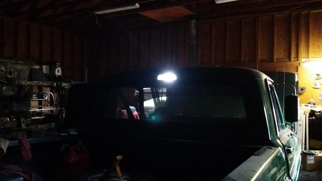
The red/white switchback LED I ordered several weeks ago finally showed up in the mail yesterday. I finished up the wiring connections on the cargo light housing/socket just a little bit ago. Everything checks out on it and it works just as I had intended.
If the cargo light **** on the dash is pulled out, it illuminates the bed of the truck, just as it used to with the incandescent bulb.
(the brightness of the LED doesn't really show up in the photos as it actually appears but, you get the general idea).
If the brake pedal is stepped on, the switchback LED changes to red.
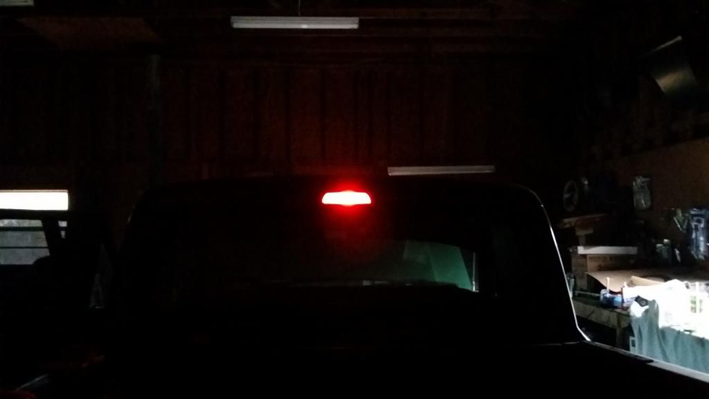
If there's something wrong and the truck has to be pulled over to the side of the road, the '3rd brake light' flashes red along with the hazard lights --as shown in the first part of the following video clip.
If you really want to get peoples' attention, to let them know you're on the side of the road, so they don't run into you, the cargo **** can be pulled out, in conjunction with the flashers being on and the cargo light/3rd brake light will alternate between red and white.
http://vid1093.photobucket.com/album...pszwh2nsvt.mp4
I got the front sway bar put on today --now, that item can be checked off the to-do list.
The red/white switchback LED I ordered several weeks ago finally showed up in the mail yesterday. I finished up the wiring connections on the cargo light housing/socket just a little bit ago. Everything checks out on it and it works just as I had intended.
If the cargo light **** on the dash is pulled out, it illuminates the bed of the truck, just as it used to with the incandescent bulb.
(the brightness of the LED doesn't really show up in the photos as it actually appears but, you get the general idea).

If the brake pedal is stepped on, the switchback LED changes to red.

If there's something wrong and the truck has to be pulled over to the side of the road, the '3rd brake light' flashes red along with the hazard lights --as shown in the first part of the following video clip.
If you really want to get peoples' attention, to let them know you're on the side of the road, so they don't run into you, the cargo **** can be pulled out, in conjunction with the flashers being on and the cargo light/3rd brake light will alternate between red and white.
http://vid1093.photobucket.com/album...pszwh2nsvt.mp4
The following users liked this post:
#323
02-02-2015, 12:34 PM
Thanks.
3rd brake lights were mandatory on new vehicles sold in the U.S., starting in 1986. In 1969, nobody knew what a 3rd brake light was.
Now, my old truck has a safety feature of a modern day vehicle, --with a little extra twist added into it.
I'll have to post the LED bulb information this evening, after I get home from work.
#324
02-02-2015, 06:40 PM
The LED came from Autolumination.com . It's a switchback LED listed as; 60 LED Prec. The colors I got are White-Red.
I got an 1157 metal socket from Summit racing. The part number for it is; 84725. It has two contact wires (black) and one ground wire (white). It had some tabs around the opening of the socket that weren't needed. I took some needle nose pliers and broke them off the socket housing.
When I went to insert the LED into the socket, I accidently broke the THIN fiberglass wafer that keeps the contacts of the wires located and separated. The wafer is keyed so, make sure it's lined up in the slot BEFORE you try to put the LED in the metal socket. I went to O'Reilly Auto Parts and got a replacement contact/wire set to install in the socket, p/n 85801.
Off and on, I had tried to come up with a way to double the cargo light as a 3rd brake light but, I just couldn't come up with a clean and easy solution to accomplish this.
A while back, I had seen on Fordification where a guy had done this with a switchback LED (which before then, I didn't know such a thing even existed). The main credit goes to Coupe5oh in figuring this out.
However, his description of how he did it only consisted of mentioning where he got the LED, he said he used a universal 1157 socket and he ran another circuit to go to the cargo light (and I believe he said) he wired it into the rear brake lights (?). I just sort of had to fill in the blanks of the unknowns of how it was done, to make the modifications to my cargo light, and how I wired mine to get it to work the way it does now.
Coupe5oh posted two photos: one of the cargo light lit up white, with the cargo light **** pulled out and, one of it lit up red, when the brakes were applied.
I have no idea in his setup if the cargo light flashes red when the flashers are on or, if it will alternate between red/white when the flashers AND the cargo **** are activated (?).
I wired my 3rd brake light circuit off the switched side of the brake pedal switch. My factory brake switch mounts to a bracket under the dash. It's a normally closed switch, held open. There are two wires on the spade connector that plugs into the back of the switch. One wire is Red/Black. This is the constant 12v hot wire to the switch. The other wire is solid Red. It's the wire on the switched side of the circuit. --this circuit is dead when the pedal is back because the switch contacts are being held open (no current/voltage flow through it).
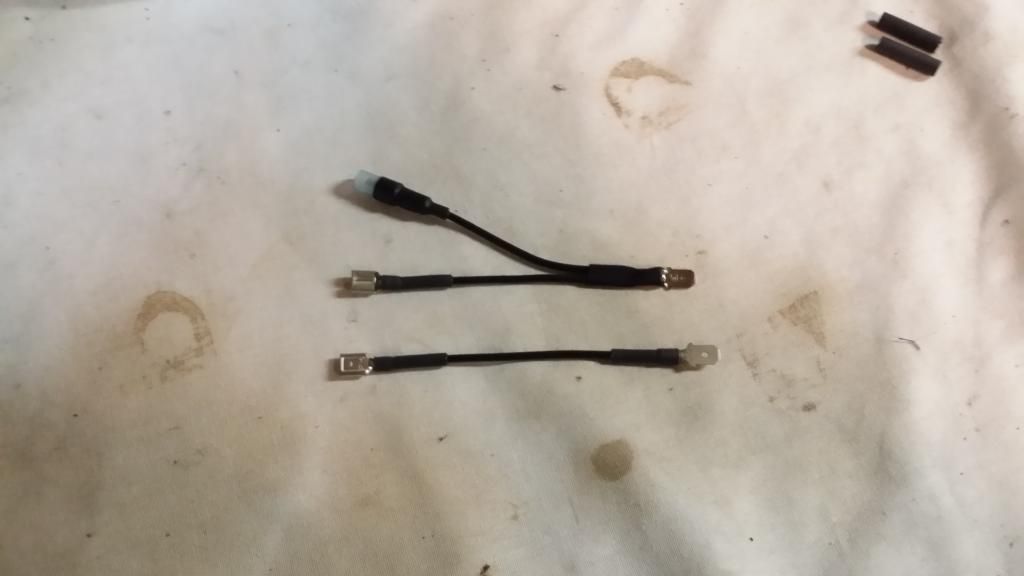
I took the factory connector loose from the back of the brake pedal switch and made two short jumpers with spade connectors at each end. On one of the jumpers for the switched side (Red wire) of the brake switch, I made a breakout pigtail and attached a .157" female bullet terminal. --this breakout would be connected to the circuit going to the cargo light, to turn on the red portion of the LED.
These are the jumpers (patch wires) I made to go between the spade terminals of the brake switch and the wiring harness connector that used to plug into the brake switch. The top jumper in the photo is the one with the breakout and the female bullet terminal attached.
The jumpers installed in between the switch and the original wiring connector (wires have since been wire-tied and tucked away from when this photo was taken --and there were also no factory wiring harness wires cut).
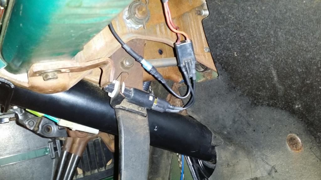
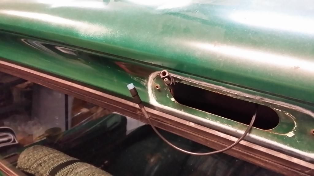
I put a male bullet terminal on some black 14 ga. automotive primary wire, plugged it into the breakout jumper, fed the wire behind the instrument cluster, up through the A-pillar, over the top of the drivers door and then around to the opening where the cargo light mounts. --this was really easy, given the fact I don't (presently) have a headliner.
Wire fed up through the hole in the A-pillar, behind where the left end of the instrument cluster is located.
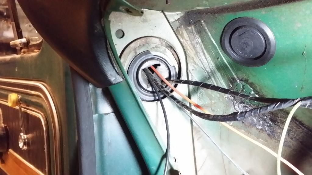
New wire (with female bullet connector attached) poking out of the hole along with the original cargo light male/female moulded bullet connector. (it took 11' of 14 ga. wire to get from the brake switch to the hole for the cargo light).
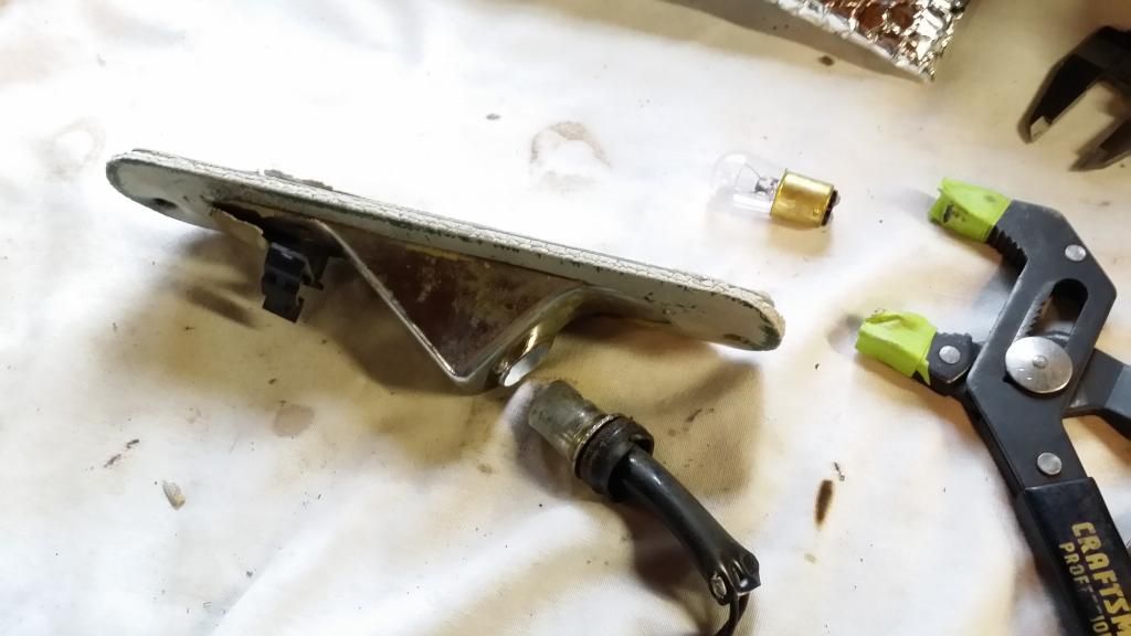
The original socket in the cargo light housing is an 1156. It's designed for a bulb with a single filament (one function). For this to work, the 1156 single filament metal socket has to be swapped for a dual filament 1157 socket.
Original 1156 socket in the housing of the cargo light.
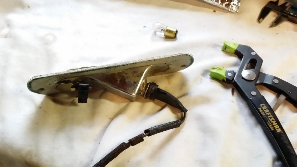
I just took some channel locks, gripped the metal ridge around the outside of the socket and twisted it back and forth while pulling outward on it and the socket slid out of the housing.
1156 socket removed from housing.
I didn't really document the steps beyond this with photos but, I took my die grinder with a carbide bit and had to make (3) small divots in the I.D. of the cargo light housing for the 1157 metal socket to slide in --two divots to clear the ears on the socket for the offset tabs on each side of the bulb, where its base plugs into the socket and, one divot to clear the keyed tab that runs the length of the metal socket. --remove a little material at a time, try to install the socket into the housing until the socket will finally slide into the bore fairly tight.
The new base will have a wired ground so, it will not be dependent on the 1157 socket being absolutely tight to the cargo light housing for its ground path.
Once the socket will fit into the housing, slide it back out and install the switchback LED into the socket, then install the socket/LED into the housing as a unit --it will be harder to install the LED into the socket if the socket is installed into the housing, first.
After the LED/socket are installed, JB Weld the socket to the housing and let it harden.
Now, you can check which black wire of the socket illuminates the LED white and which goes to the red.
Once I figured this out, I marked the wires, clipped the male/female moulded bullet connector off the old 1156 socket, spliced the appropriate terminal to the wire of the socket going to the white portion of the LED, connected the white (ground) wire to the other bullet terminal on the original moulded connector from the old socket and then, connected the wire I ran from the brake switch to the other black wire on the 1157 socket that illuminates the red portion of the LED.
This modification is really pretty easy to do. The explanation is just lengthy in trying to explain how I did it.
I got an 1157 metal socket from Summit racing. The part number for it is; 84725. It has two contact wires (black) and one ground wire (white). It had some tabs around the opening of the socket that weren't needed. I took some needle nose pliers and broke them off the socket housing.
When I went to insert the LED into the socket, I accidently broke the THIN fiberglass wafer that keeps the contacts of the wires located and separated. The wafer is keyed so, make sure it's lined up in the slot BEFORE you try to put the LED in the metal socket. I went to O'Reilly Auto Parts and got a replacement contact/wire set to install in the socket, p/n 85801.
Off and on, I had tried to come up with a way to double the cargo light as a 3rd brake light but, I just couldn't come up with a clean and easy solution to accomplish this.
A while back, I had seen on Fordification where a guy had done this with a switchback LED (which before then, I didn't know such a thing even existed). The main credit goes to Coupe5oh in figuring this out.
However, his description of how he did it only consisted of mentioning where he got the LED, he said he used a universal 1157 socket and he ran another circuit to go to the cargo light (and I believe he said) he wired it into the rear brake lights (?). I just sort of had to fill in the blanks of the unknowns of how it was done, to make the modifications to my cargo light, and how I wired mine to get it to work the way it does now.
Coupe5oh posted two photos: one of the cargo light lit up white, with the cargo light **** pulled out and, one of it lit up red, when the brakes were applied.
I have no idea in his setup if the cargo light flashes red when the flashers are on or, if it will alternate between red/white when the flashers AND the cargo **** are activated (?).
I wired my 3rd brake light circuit off the switched side of the brake pedal switch. My factory brake switch mounts to a bracket under the dash. It's a normally closed switch, held open. There are two wires on the spade connector that plugs into the back of the switch. One wire is Red/Black. This is the constant 12v hot wire to the switch. The other wire is solid Red. It's the wire on the switched side of the circuit. --this circuit is dead when the pedal is back because the switch contacts are being held open (no current/voltage flow through it).
I took the factory connector loose from the back of the brake pedal switch and made two short jumpers with spade connectors at each end. On one of the jumpers for the switched side (Red wire) of the brake switch, I made a breakout pigtail and attached a .157" female bullet terminal. --this breakout would be connected to the circuit going to the cargo light, to turn on the red portion of the LED.
These are the jumpers (patch wires) I made to go between the spade terminals of the brake switch and the wiring harness connector that used to plug into the brake switch. The top jumper in the photo is the one with the breakout and the female bullet terminal attached.

The jumpers installed in between the switch and the original wiring connector (wires have since been wire-tied and tucked away from when this photo was taken --and there were also no factory wiring harness wires cut).

I put a male bullet terminal on some black 14 ga. automotive primary wire, plugged it into the breakout jumper, fed the wire behind the instrument cluster, up through the A-pillar, over the top of the drivers door and then around to the opening where the cargo light mounts. --this was really easy, given the fact I don't (presently) have a headliner.
Wire fed up through the hole in the A-pillar, behind where the left end of the instrument cluster is located.

New wire (with female bullet connector attached) poking out of the hole along with the original cargo light male/female moulded bullet connector. (it took 11' of 14 ga. wire to get from the brake switch to the hole for the cargo light).

The original socket in the cargo light housing is an 1156. It's designed for a bulb with a single filament (one function). For this to work, the 1156 single filament metal socket has to be swapped for a dual filament 1157 socket.
Original 1156 socket in the housing of the cargo light.

I just took some channel locks, gripped the metal ridge around the outside of the socket and twisted it back and forth while pulling outward on it and the socket slid out of the housing.
1156 socket removed from housing.

I didn't really document the steps beyond this with photos but, I took my die grinder with a carbide bit and had to make (3) small divots in the I.D. of the cargo light housing for the 1157 metal socket to slide in --two divots to clear the ears on the socket for the offset tabs on each side of the bulb, where its base plugs into the socket and, one divot to clear the keyed tab that runs the length of the metal socket. --remove a little material at a time, try to install the socket into the housing until the socket will finally slide into the bore fairly tight.
The new base will have a wired ground so, it will not be dependent on the 1157 socket being absolutely tight to the cargo light housing for its ground path.
Once the socket will fit into the housing, slide it back out and install the switchback LED into the socket, then install the socket/LED into the housing as a unit --it will be harder to install the LED into the socket if the socket is installed into the housing, first.
After the LED/socket are installed, JB Weld the socket to the housing and let it harden.
Now, you can check which black wire of the socket illuminates the LED white and which goes to the red.
Once I figured this out, I marked the wires, clipped the male/female moulded bullet connector off the old 1156 socket, spliced the appropriate terminal to the wire of the socket going to the white portion of the LED, connected the white (ground) wire to the other bullet terminal on the original moulded connector from the old socket and then, connected the wire I ran from the brake switch to the other black wire on the 1157 socket that illuminates the red portion of the LED.
This modification is really pretty easy to do. The explanation is just lengthy in trying to explain how I did it.
#325
02-02-2015, 07:21 PM
#326
02-02-2015, 09:12 PM
You can find the LED ("60 Led Switchback*Two Colors - One Bulb") about the middle of the page at this link:
Tail Lights LED Flashing
I don't have a ballast resistor on the LED. LEDs draw significantly less amperage than a conventional incandescent bulb(s). If you put LEDs in place of an incandescent bulb, it can cause 'hyper flashing' where the lights blink rapidly.
This is caused when the blinker relay senses low current from a circuit (thinks the bulb is burned out) and blinks rapidly to let you know you have a signal light(s) that aren't working --or, at least it 'thinks' the bulb is out. --In a modern vehicle, this can generate problem codes on the vehicle processor.
I plan to install 1157 red LEDs in the tail lights and 1157 yellow LEDs in front turn signal/parking light housings.
There are 2-way and 4-way LED compatible flashers (designed to get rid of hyper flashing) that I'll replace my regular flasher relays with.
I'll have to do some more research on this but, I don't know if the only purpose of the external ballast resistors is just to stop the LEDs from hyper flashing (?), or if they have a secondary function to reduce voltage/amperage to the LEDs (?).
IF no voltage/amperage control is needed and IF the purpose of the resistors is only to stop hyper flashing, it would be much simpler and more professional looking to simply change out the regular flasher relays to ones designed for LEDs than to have clunky resistors spliced into, and hanging off of, the wires.
#327
02-02-2015, 09:38 PM
#328
02-03-2015, 07:11 AM
Thanks. I was originally thinking along the same basic lines as you --I thought about the outer rows being white LEDs and the inner rows being red but after I found out about the switchback LED, the solution was MUCH cleaner and simpler to accomplish this.
#329
02-03-2015, 04:24 PM
Thanks, Moe.
You can find the LED ("60 Led Switchback*Two Colors - One Bulb") about the middle of the page at this link:
Tail Lights LED Flashing
I don't have a ballast resistor on the LED. LEDs draw significantly less amperage than a conventional incandescent bulb(s). If you put LEDs in place of an incandescent bulb, it can cause 'hyper flashing' where the lights blink rapidly.
This is caused when the blinker relay senses low current from a circuit (thinks the bulb is burned out) and blinks rapidly to let you know you have a signal light(s) that aren't working --or, at least it 'thinks' the bulb is out. --In a modern vehicle, this can generate problem codes on the vehicle processor.
I plan to install 1157 red LEDs in the tail lights and 1157 yellow LEDs in front turn signal/parking light housings.
There are 2-way and 4-way LED compatible flashers (designed to get rid of hyper flashing) that I'll replace my regular flasher relays with.
I'll have to do some more research on this but, I don't know if the only purpose of the external ballast resistors is just to stop the LEDs from hyper flashing (?), or if they have a secondary function to reduce voltage/amperage to the LEDs (?).
IF no voltage/amperage control is needed and IF the purpose of the resistors is only to stop hyper flashing, it would be much simpler and more professional looking to simply change out the regular flasher relays to ones designed for LEDs than to have clunky resistors spliced into, and hanging off of, the wires.
#330
02-03-2015, 07:08 PM
The truck gods finally smiled on me today and bestowed upon me a bounty of the correct axle bearings/collars and axle seals.
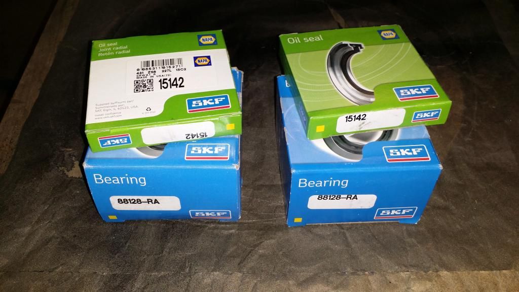
Time to press them on. The bearing slid onto the axle.
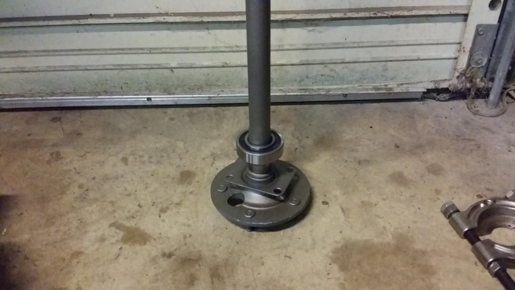
I removed the inner race from one of the old bearings I had previously removed from one of the 31-spline axles. I took my die grinder with a carbide bit and slightly opened up the I.D. of the old bearing race --so the interference fit of it won't get stuck on the axle. I placed the old inner bearing race on top of the new bearing.
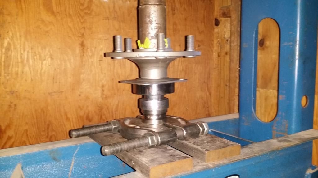
Then, I placed the bearing separator on top of the old inner bearing race.
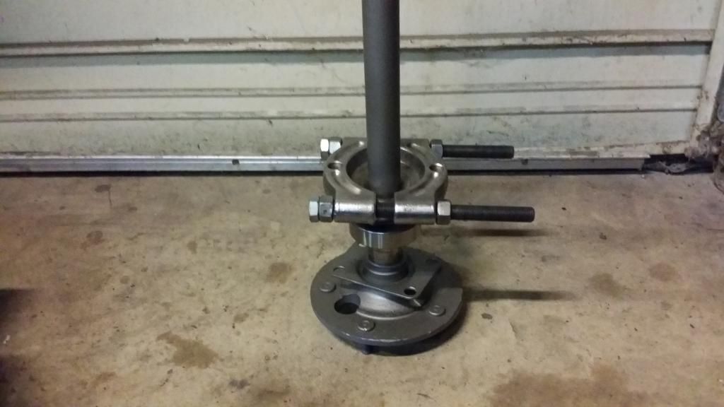
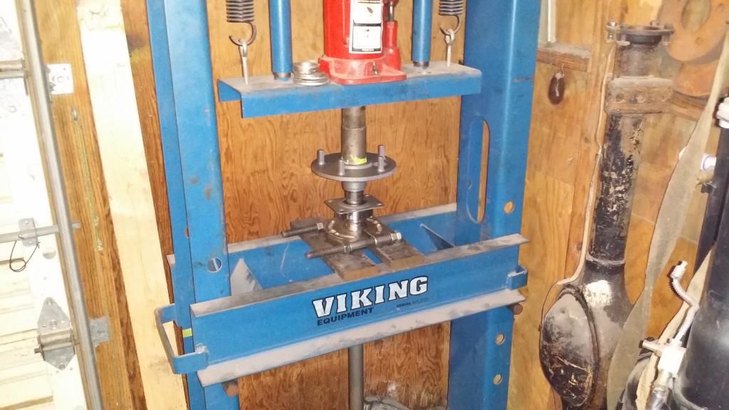
The 'assembly' set into place over in the 20-ton press. --the separator will press against the old inner bearing race (spacer), which will push directly against the inner race on the new bearing and will drive the new bearing onto the bearing seat of the axle journal. The spacer will keep any load and stress from being placed directly on the bearing itself.
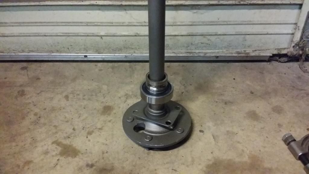
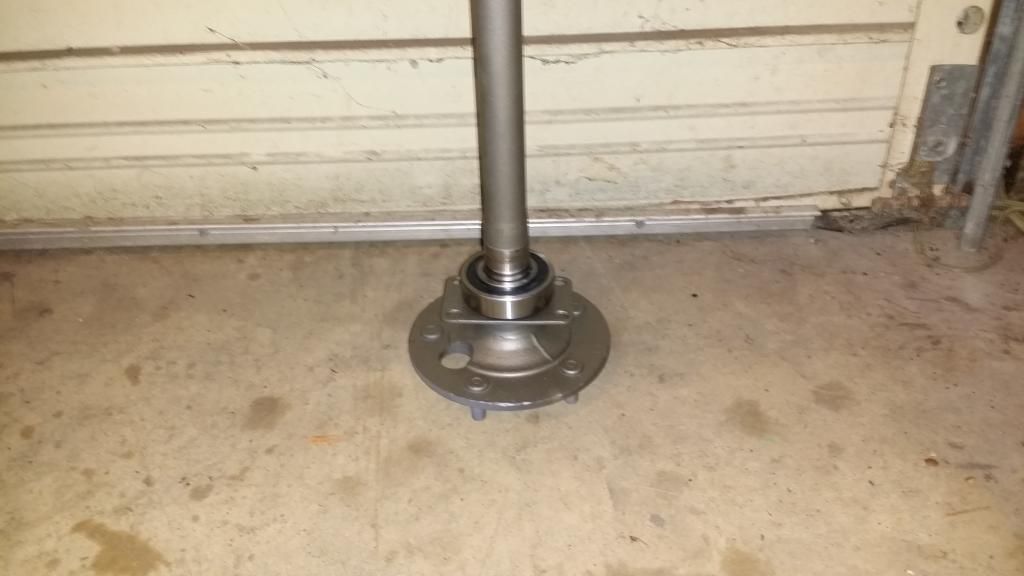
New axle bearing pressed onto the axle. Time to press the bearing retainer collar on.
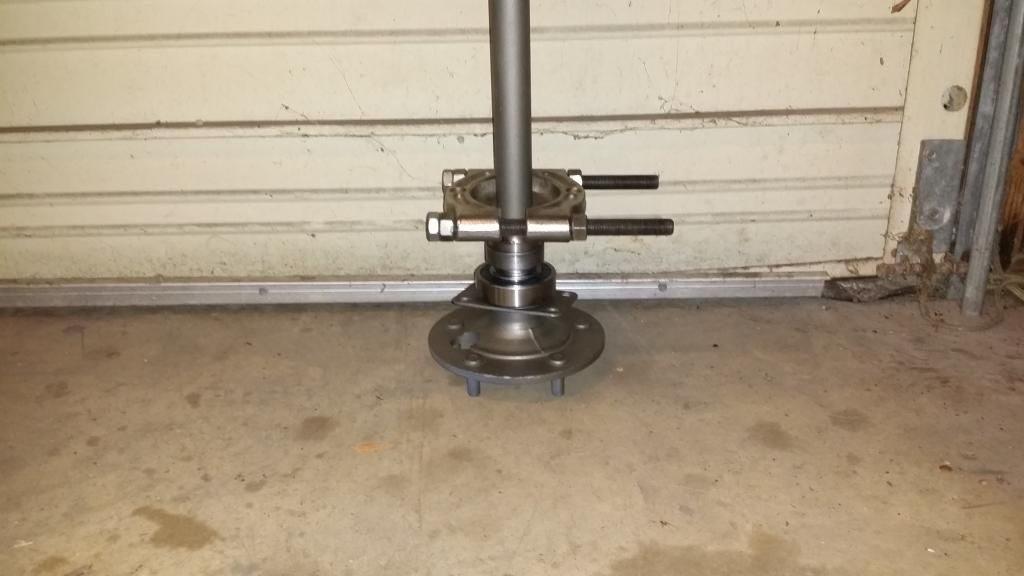
Bearing retaining collar, spacer and bearing separator in place and ready to put the axle back in the press to press the collar on.
Axle bearing and retaining collar pressed on --axle ready to be installed in the housing.
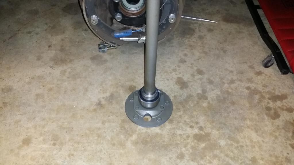
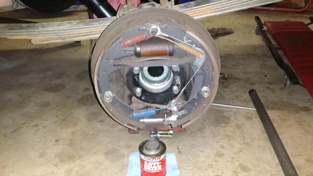
....but first, I took a little bit of fresh gear oil and smeared it around the rubber portion of the axle seal and on the journal of the axle, where the seal will be riding. I also smeared a thin layer of Anti-Seize on the bearing socket on the end of the axle tube, just prior to installing the axle (the 'silvery' looking stuff in the photo). This will keep the axles from getting stuck to the housing, so they will come out easily if they have to be pulled out sometime in the future.
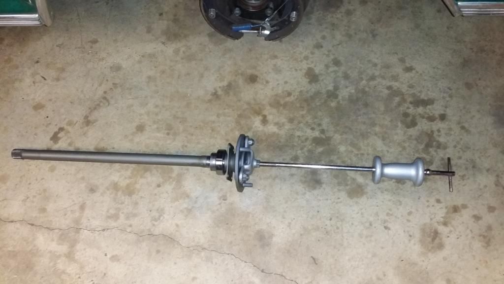
Here's our old friend, Mr. Slide Hammer. (what's he doing here?). He's going to help assist me in putting the axle back into the housing. He's good for counter-balancing the weight of the axle and, he makes a good handle too. He's also going to help me hold the weight of the axle up, while I put the axle into the housing. --don't want any pesky premature leaks caused by nicks or tears from the weight of the axle dragging across the seals .
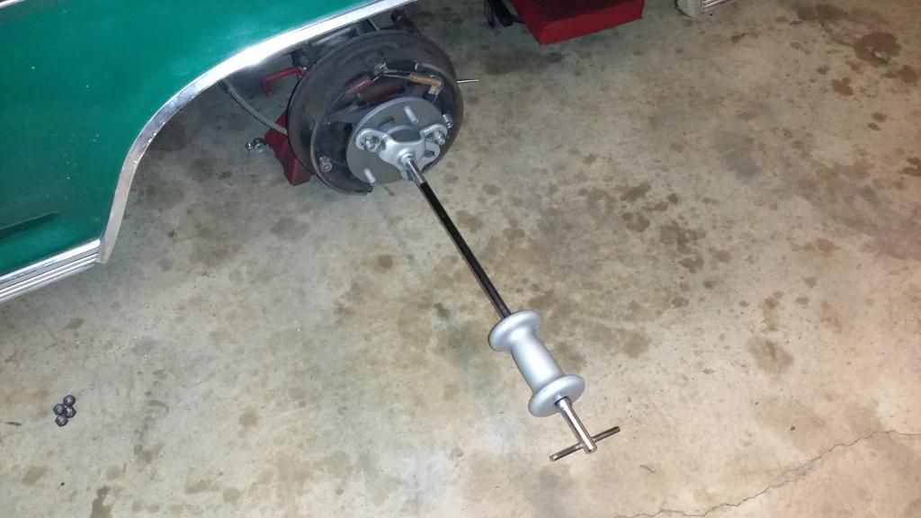
Axle installed, axle retainer bolted down and, it's in there! ....time to repeat the same process for the other side.

Time to press them on. The bearing slid onto the axle.

I removed the inner race from one of the old bearings I had previously removed from one of the 31-spline axles. I took my die grinder with a carbide bit and slightly opened up the I.D. of the old bearing race --so the interference fit of it won't get stuck on the axle. I placed the old inner bearing race on top of the new bearing.

Then, I placed the bearing separator on top of the old inner bearing race.

The 'assembly' set into place over in the 20-ton press. --the separator will press against the old inner bearing race (spacer), which will push directly against the inner race on the new bearing and will drive the new bearing onto the bearing seat of the axle journal. The spacer will keep any load and stress from being placed directly on the bearing itself.

New axle bearing pressed onto the axle. Time to press the bearing retainer collar on.

Bearing retaining collar, spacer and bearing separator in place and ready to put the axle back in the press to press the collar on.


Axle bearing and retaining collar pressed on --axle ready to be installed in the housing.

....but first, I took a little bit of fresh gear oil and smeared it around the rubber portion of the axle seal and on the journal of the axle, where the seal will be riding. I also smeared a thin layer of Anti-Seize on the bearing socket on the end of the axle tube, just prior to installing the axle (the 'silvery' looking stuff in the photo). This will keep the axles from getting stuck to the housing, so they will come out easily if they have to be pulled out sometime in the future.

Here's our old friend, Mr. Slide Hammer. (what's he doing here?). He's going to help assist me in putting the axle back into the housing. He's good for counter-balancing the weight of the axle and, he makes a good handle too. He's also going to help me hold the weight of the axle up, while I put the axle into the housing. --don't want any pesky premature leaks caused by nicks or tears from the weight of the axle dragging across the seals .


Axle installed, axle retainer bolted down and, it's in there! ....time to repeat the same process for the other side.
