When you click on links to various merchants on this site and make a purchase, this can result in this site earning a commission. Affiliate programs and affiliations include, but are not limited to, the eBay Partner Network.
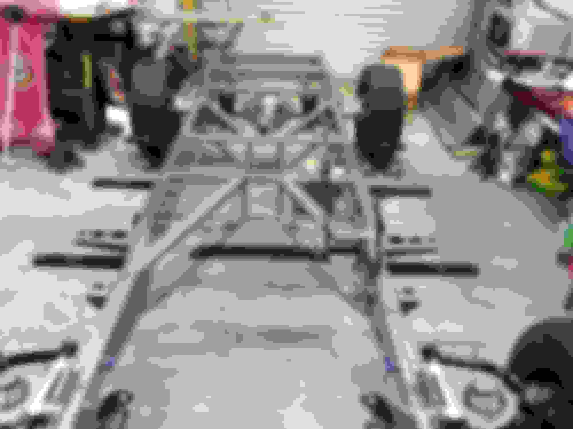
Currie 9" 3.5 posi and airbags
front suspension, with coil overs Above, are some good shots of the pwr brakes, clutch master cylinder and Wilwood rear brake
pressure adjuster
On the Moroso oil pan, for a Mustang II front suspension, the front sump drain plug hit the rack and pinion unit. So, I plugged and ground down the factory drain, and added my own to the bottom. The drain is well protected.
I also installed a oil temp sensor in the back sump.
I'm a bit of a sensor nut, so I also installed a temp sender in the rear end and the Tremec TKO-600 5 spd transmission.
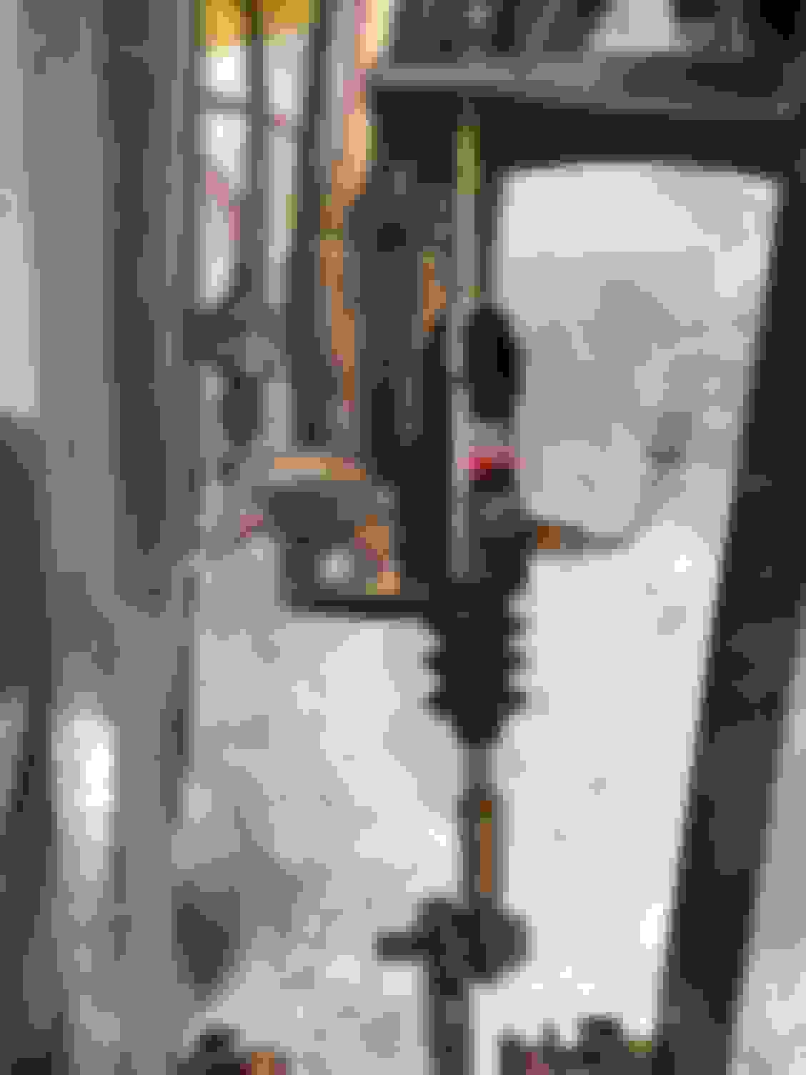
I decided to go with a Flaming River tilt steering column. I mounted it with a short drop mount and because the original ford mount was similar, I didn't have to add any reinforcements.
From this angle, you also see I had to cut/split my gear shift to tilt it forward to prevent seat interference.... it will be welded up later.
The floor pan was modified with in and out column adapters.
With the headers (FordPowerTrain) in place, I was unable to run the steering shaft direct from the rack and pinion u-joint to the steering column end u-joint.... so I had to add a 3rd u-joint to go around the headers.
Here you see the bracket I made out of 2" angle iron and the additional support needed for the middle 3rd u-joint. It really turned out well.
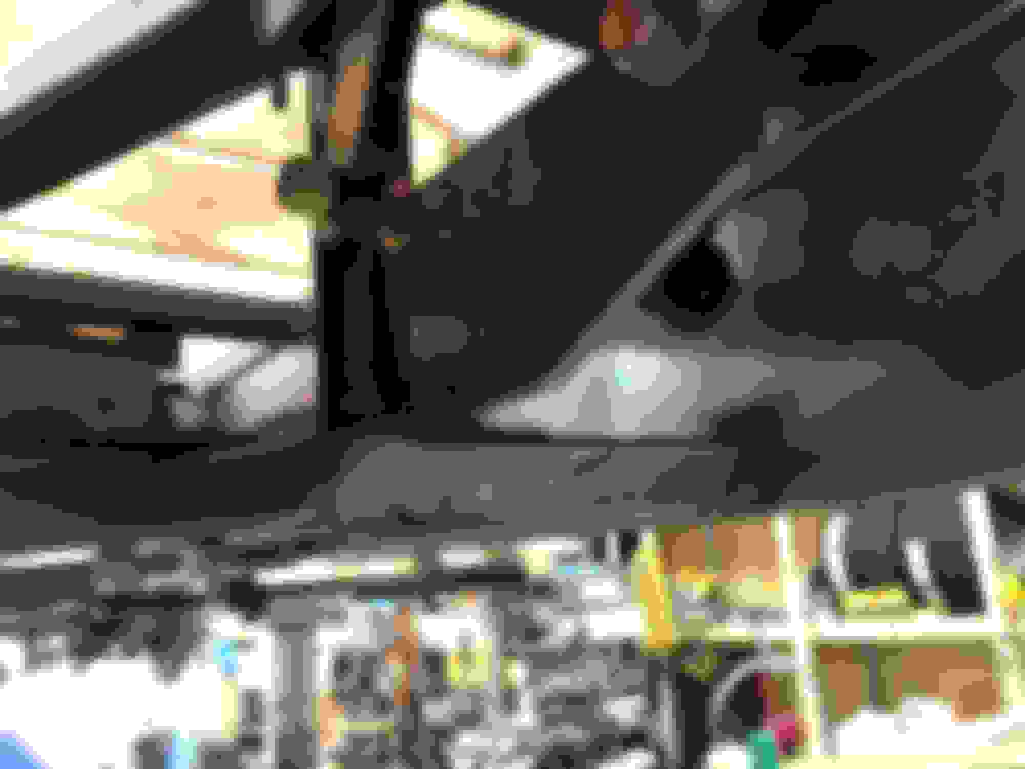
Today I had to make changes to the lower forward x-braces to allow room for my 3+ exhaust out of the headers. The X-brace interfered and didn't allow room for my exhaust to exit. Also, I made a mount for the clutch slave cylinder.
In the picture above, you can see the two (L & R) lower frame x-bracing. I need to cut them just forward of the trans mount cross member (black).
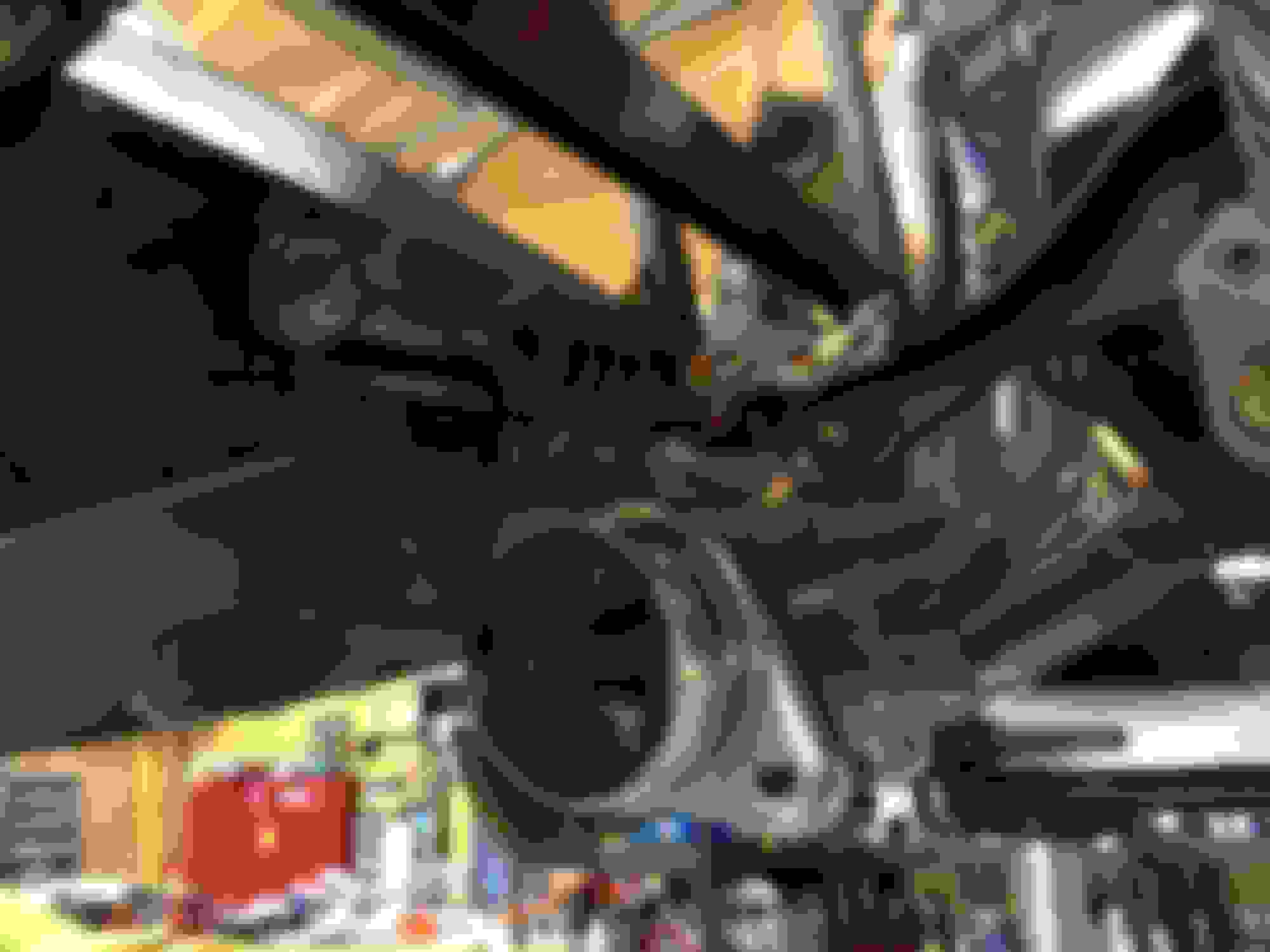
In this shot, you see the lower left x-brace with the left header collector and the lack of clearance.
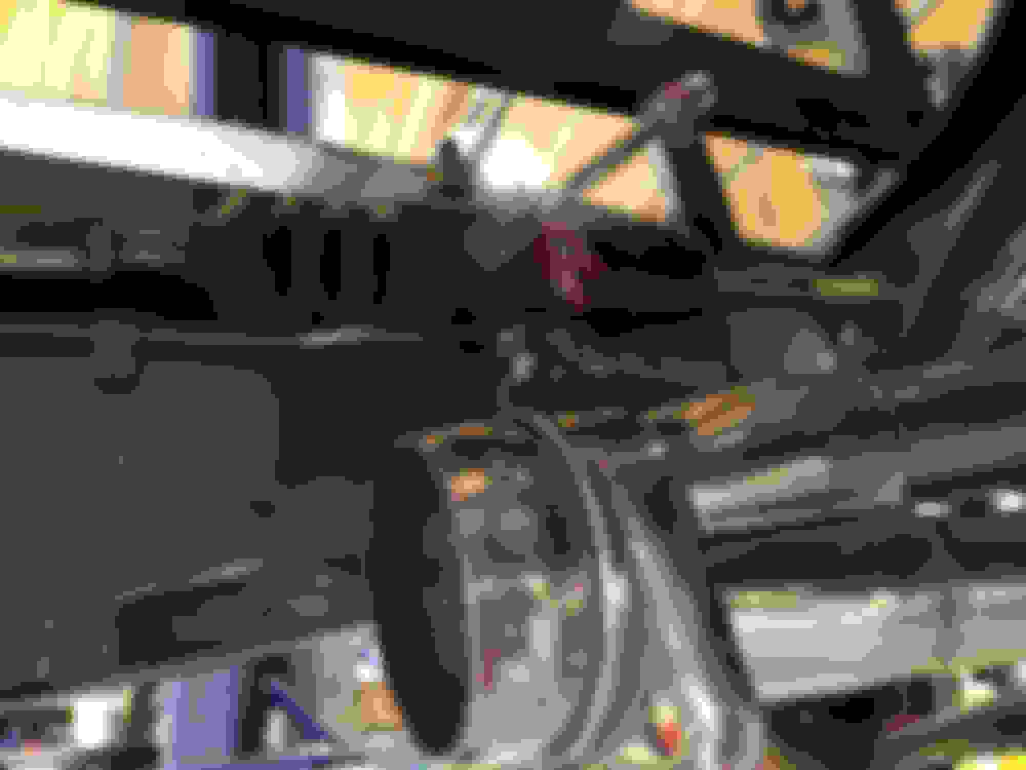
Here, you can see I added a vertical 1" angle iron to tie the top and bottom x-braces. The angle also serves as an attachment point for the plate that the rear of the slave cylinder attaches to. The bottom x-brace was cut and I ran a 1" strap from the braces end to the side of the frame.
In this shot, you can clearly see where I cut the x-brace from the frame. I was also happy so see the green internal frame coating I applied went down the length of the x-brace and coated the frame also.
I'll add heat shielding between the header and the slave cylinder and clutch fluid lines.
Here you can see I added an additional piece of metal to the plate the slave cylinder mounts to. It's a 2"x 2" piece welded in place and then I drilled a 5/16" hole for the grade 8 mounting bolt.
I'm going for a more "finished" look and decided to cap off the beds side and front end panel ends.
I was considering the billet end plugs, but then thought it was too much of an eye catch. This way only those with knowledge of the original rolled steel would know of the change.
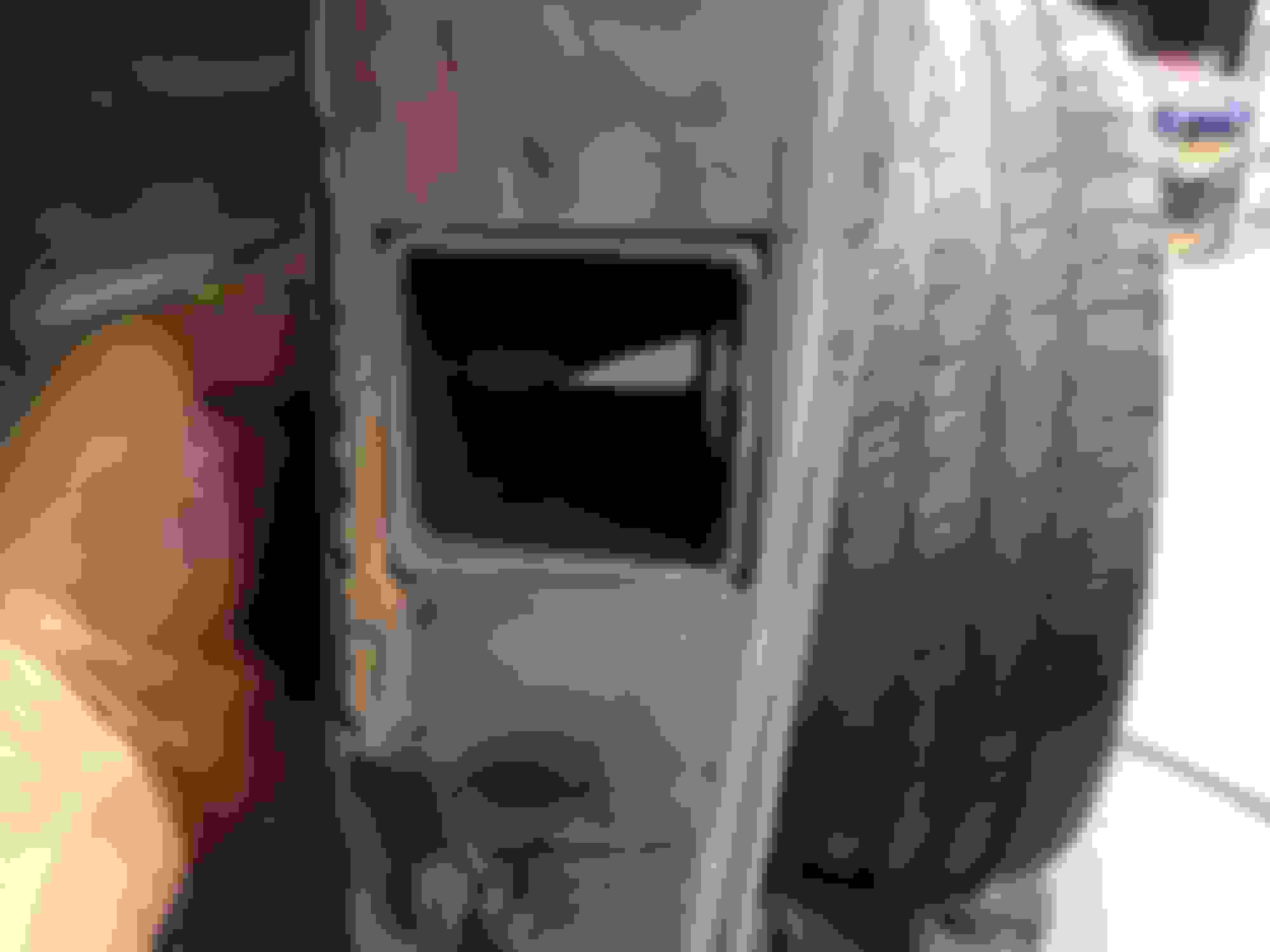
From inside the passenger door, you can see I added a 3rd brake light and a seat belt shoulder harness attachment plate. I decided that since this truck will be my daily driver I wanted the extra safety factor. Let's face it, the small tail/brake lights and their low placement isn't the attention getter I want. I did however upgrade to LED tail/brake lights/lens.
Here's an outside view of the 3rd brake light. I still have to weld up the seam.
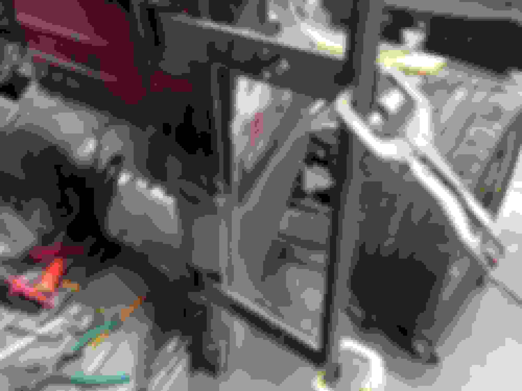
I purchased a modern aluminum radiator that fit exactly as the original and bolts in using the factory mounting points. To give me more room for the electric fans, I also had to move the radiator support into the six cylinder position and giving approx. 3" more room in front of the March Performance pulley system mounted to the 351W engine. The fans still had to have a low front to back profile and you'll also notice I went with 2 smaller fans vs one larger one..... reason?... the low profile large fan didn't pull enough air (CFM) that I wanted, so with two 11" fans I was able to increase CFMs by a considerable % amount. The controller I'm using allows for variable fan speed which I'll set, example, lower temp = 80% fan speed and higher temp = 100%.
In this shot, you can clearly see the close fit and why I needed the extra 3".
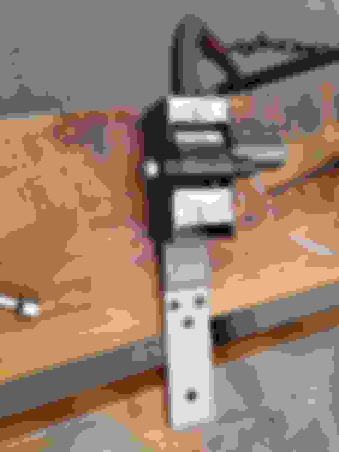
To give the exterior a little cleaner look, I decided to remove the original door hinges and install inside hidden hinges.
This is a shot of a single hinge... it shows the box that needs mounted in the A-Pillar and the swing arm that will attach to the door box that will need cut into the door.
This is a close up of one of the internal hinge box to be installed in the A-Pillar.
Once the hole is cut and the hinge box aligned, I tack welded in place.
After both top and bottom hinge boxes are tacked in, I installed the swing arms, clamped a 1" piece of angle iron to both arms to insure the arms swung freely and didn't bind anywhere.
While the angle iron was still attached, I added additional bracing to the hinge boxes. I tied both boxes together, triangled to the fire wall and the rear of each box to the A-pillar. I also finished welding up the box faces to the A-pillar.
In the next post, I'll show the doors boxes being installed.
Besides the need for very good craft skills, this thread mainly demonstrates to me the technical difficulty in a frame swap - even with a spec designed solution.
Besides the need for very good craft skills, this thread mainly demonstrates to me the technical difficulty in a frame swap - even with a spec designed solution.
DW, Why do you feel the frame swap if technically difficult? I'm very interested in your thoughts... Mark
 09-22-2014, 05:03 PM