understanding vacuum line diagram
#1
 07-10-2013, 08:06 AM


Join Date: Feb 2004
Posts: 19
Likes: 0
Received 0 Likes
on
0 Posts
understanding vacuum line diagram
Hello. I need some help understanding where the parts on the diagram are located on the engine. Yesterday, I found out what all the abbreviations stand for, but now I don’t know where those parts are located on the engine. I can do the work, but I know little to nothing about engines. Can someone show me where each part of the diagram is in relation to my engine? I just replaced the timing chain and sprockets and now I think the vacuum lines may be wrong as I think I may have messed around with them before knowing where each one goes. I can get it to crank but when I put it into gear, it shuts off. I think I may have to get a new electric choke as well. I don’t have any type of gages to do testing on vacuum flow or any type of pressure tests. ’83 E350 460 7.5l (with carb) Motorhome.
Any help is greatly appreciated!
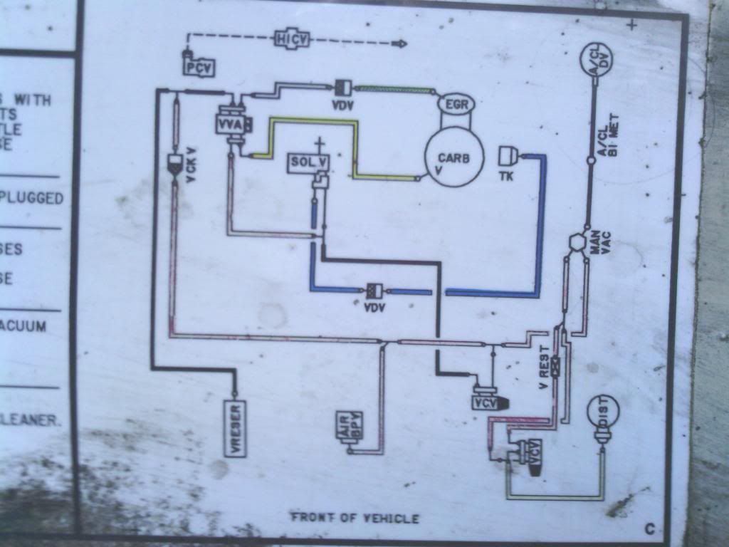
Diagram on the hood
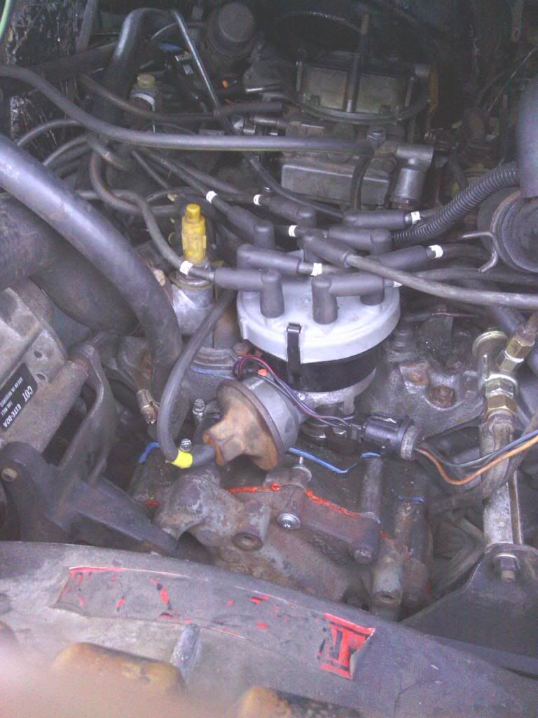
Front

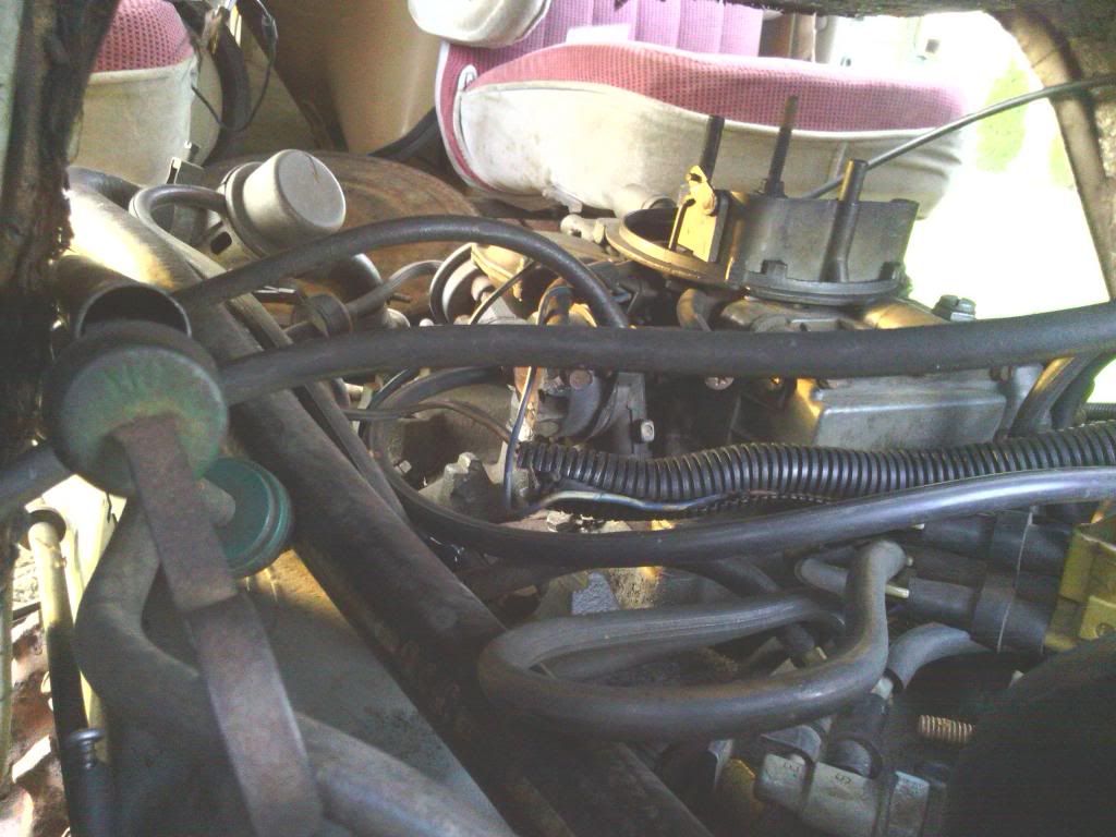
Passenger side of holley

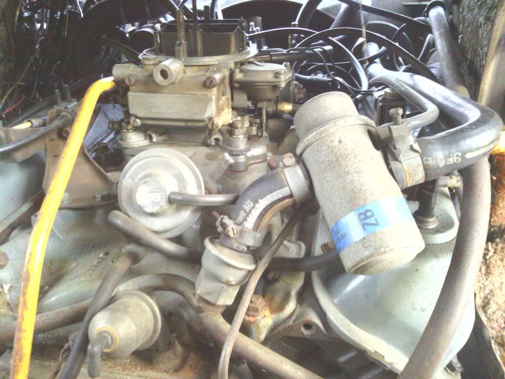
Driver's side of holley

Unknow what all the parts are..
Brighter picture
Inside of cab
Any help is greatly appreciated!

Diagram on the hood

Front

Passenger side of holley

Driver's side of holley

Unknow what all the parts are..

Brighter picture

Inside of cab
#2
07-10-2013, 12:42 PM

Looks like most of it is there! In pic#4 I see tagged plug wire#5 running under the Throttle Kick back valve, (KT) in #1 pic, it moves in and out (pinch point) and pushes on the throttle linkage to keep it from stalling when you turn on the A/C, come to a stop, or put trans in drive or reverse, keep that area clear! But that Holley carb might of seen better days and will give you a lot of trouble until the engine warms up........keep us posted.
#3
07-10-2013, 07:41 PM
Join Date: Feb 2004
Posts: 19
Likes: 0
Received 0 Likes
on
0 Posts
Thank you, econolinemanor. That is a great start; I now know which part on the engine is the TK. I think I found the (2) VCV’s and The EGR. Now I just have to locate which engine component is the:
A/CL DV
A/CL BI MET
MAN VAC
V REST
AIR BPV
VRESER
VDV
V CK V
SOL V
HICV
VVA
Any chance you could tell me where these are located in the pictures posted above as well? Also, my Holley has 2 lines coming off of it on the passenger’s side however the diagram only shows 1 (marked "V"). Does it matter which one is capped off?
Thank you again for the help!
#4
07-11-2013, 10:54 AM
Glad to help, I don't have a picture account to post from or I could mark them. NOT in the pics is the A/CL DV on the Air Cleaner housing inlet (Air Cleaner Diverter valve) and that connects to the A/CL BI MET (Air Cleaner BiMetal valve) inside the housing and under that valve a hose that connects to a Vacuum tree (ManVac) pic#1 on the Intake Manifold. But with the Air Cleaner completely off it should have some kind of plug on it or it's a vacuum leak.........
#5
07-11-2013, 12:19 PM
In pic#1 the (V CH V) is a Vacuum Check Valve (one way) and the (VDV) is a Vacuum Diverter Valve for the EGR (vacuum reducer) all 3 should be little black and white round plastic valve spliced into the vacuum hoses, I can see the EGR VDV in pic#6 but I don't see the V CH V spliced into the (TK) hose that should go to the (SOL V) Solenoid Valve...On the Holley (marked V) should go to (VVA) Variable Vacuum Actuator? that's where the other end of the EGR hose and VDV plugs into.
#6
07-11-2013, 12:56 PM
(V REST) Vacuum Resistor, another spliced in very small plastic thing, (VRESER) is the Vacuum Reservoir mounted somewhere on the passenger side! not sure where it's at for that year, and there should be a Carb connection somewhere for the EVAP canister vacuum (gas tank emissions). It will take some time to trace it all down and see what still works.........
#7
07-17-2013, 11:48 AM
Join Date: Feb 2004
Posts: 19
Likes: 0
Received 0 Likes
on
0 Posts
I am grateful for all the help! Can't wait to get this thing running again.
I think I now have most of the lines on the correct ports, but still a few more questions. Mostly about the vacuum lines to / from the carb.

The (metal) line (D) in pic #2 runs from the front of the carb back to some valve(?) in pic #1 that seems to be some type of movable switch? Do I need to adjust it or anything?
The carb has 4 vaccum lines. (pics #2 & #4).
Port "A" is plugged, Port "B" is now plugged, Port "C" is going to the VVA (pic #3), and Port "D" (pic #2) is going to an unknown part on the engine.
Which of these ports SHOULD be going to the VVA, and which ports SHOULD be capped off, or should they be going some where else?
Trending Topics
#8
07-17-2013, 12:40 PM
#9
07-17-2013, 01:00 PM
Now for (C) it looks like the Choke (Pre Heat) that comes from the Exhaust Manifold. It will be a small diameter metal tube covered in heat protected material that is force fitted into the Exhaust Manifold and the other end has a tubing style connector that screws into the Carb Choke Housing pic#4 right at where you marked (C). The Choke pre heat tube will rust off flush at the Manifold pretty quick and need to be carefully drilled out if needed.
#10
07-17-2013, 01:33 PM
#11
07-17-2013, 03:53 PM
Join Date: Feb 2004
Posts: 19
Likes: 0
Received 0 Likes
on
0 Posts
This is great info! Thanks again. And yes, it IS actually fun. 
In picture #2, directly below the choke is a diamond shaped plate bolted to the manifold. I happen to have one with a "U-shaped" metal tube on it. I am thinking that I can cut it and have one side go to "C" and the other side go to "B". That should in fact, take care of all the vacuum lines.
I think I forgot to mention that I do have the Air Cleaner Housing and have it connected to the vac lines as well.
I already changed the plugs, fuel filter going into the carb, and installed a new timing change and sprockets. Fuel pump works, fresh gas, so a few twists of the distrubitor and she should fire up and go into gear. (Hopefully without shutting off!).....
We will see in a few hours!
#12
07-18-2013, 08:06 AM
Join Date: Feb 2004
Posts: 19
Likes: 0
Received 0 Likes
on
0 Posts
Well, She fired up!
I seem to have a leak at the PCV and HIC V so I need to replace those. I hope that solves the problem of shutting off when I put it into gear. Break light is on but parking break is disengaged. Maybe low fluid. I havn't checked that yet.
I had to leave "B" uncapped and open. I connected "A" to the VVA. Seems like I might have a choke issue. (Butterfly needs to be open when first starting, but it stays shut unless I manually open it up.) I think I need to replace the electric choke.
One problem at a time and eventually I have ALL new parts!
Last edited by lilhelppls; 07-18-2013 at 08:07 AM. Reason: wouldn't save video correctly
#13
07-18-2013, 10:55 AM
#14
07-19-2013, 09:12 AM
Join Date: Feb 2004
Posts: 19
Likes: 0
Received 0 Likes
on
0 Posts

#15
07-19-2013, 01:36 PM

Thread
Thread Starter
Forum
Replies
Last Post
Xtreasurehunter
1973 - 1979 F-100 & Larger F-Series Trucks
9
08-27-2021 12:05 PM
chemaholic
1973 - 1979 F-100 & Larger F-Series Trucks
17
04-03-2018 08:45 AM
eriklane
1980 - 1986 Bullnose F100, F150 & Larger F-Series Trucks
7
05-17-2014 07:30 AM
physicsguy11
1973 - 1979 F-100 & Larger F-Series Trucks
3
04-12-2010 09:27 AM