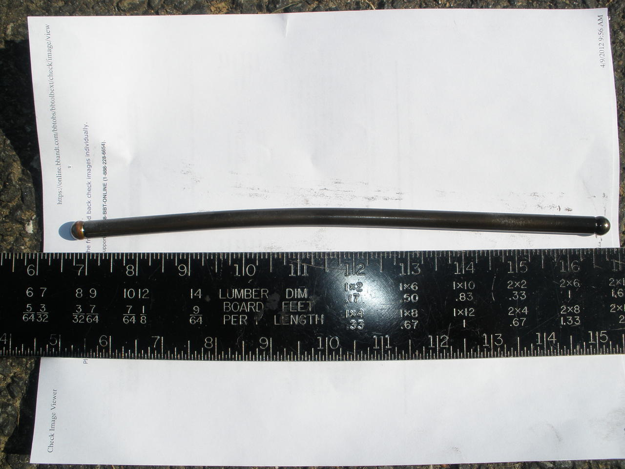
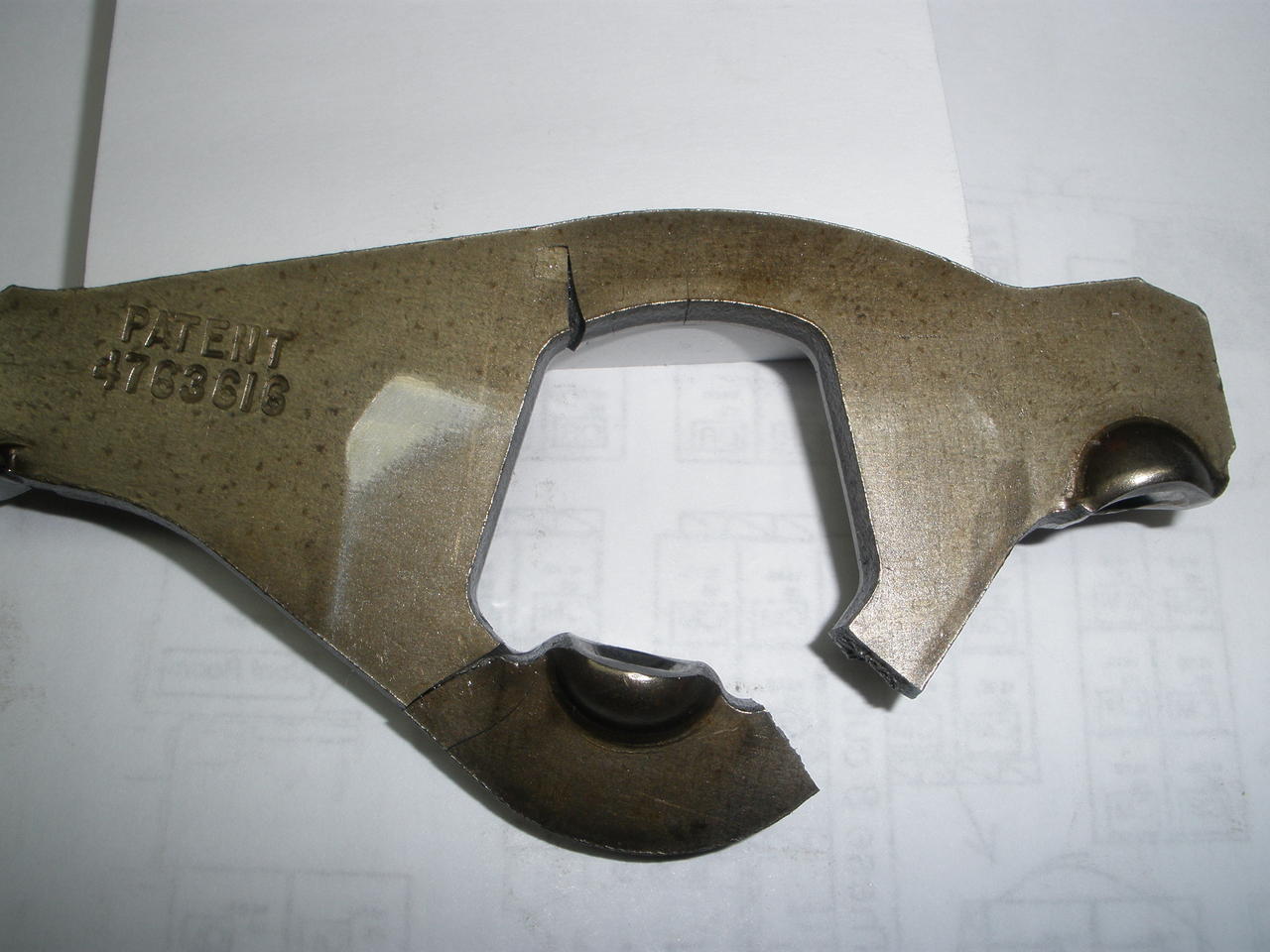
RUH ROH...this can't be good! Bent rod; cracked arm!!
#1
 05-17-2012, 06:15 PM


Join Date: Feb 2010
Location: Harford County, MD
Posts: 238
Likes: 0
Received 0 Likes
on
0 Posts
RUH ROH...this can't be good! Bent rod; cracked arm!!
Well, this is my first time removing injectors and it was going along pretty smoothly removing the injectors on my 96 7.3 PSD until I got to the number 3 cylinder. My hand brushed against the rocker arm and it was loose. I then noticed that the push rod was loose and I could simply pull it right out of the head. Noticed a little while later that the rocker arm itself is cracked in three places. Not sure what to make of this.....anyone ever seen anything like this before? Any thoughts about what to do now short of having to pull the whole engine?
This is not turning out to be the deal I thought it would be. Paid $5K for this truck about three months ago and now have at least $3k in repairs/parts and now this!!
This is not turning out to be the deal I thought it would be. Paid $5K for this truck about three months ago and now have at least $3k in repairs/parts and now this!!
#5
05-17-2012, 06:28 PM
Join Date: Feb 2010
Location: Harford County, MD
Posts: 238
Likes: 0
Received 0 Likes
on
0 Posts
#6
05-17-2012, 06:30 PM
Join Date: Feb 2010
Location: Harford County, MD
Posts: 238
Likes: 0
Received 0 Likes
on
0 Posts
Buddy of mine owns an auto shop. They don't work on diesels but I just ran it by him and he suggested the same thing. He said to try cranking it by hand first to make sure nothing is binding.
#7
05-17-2012, 06:33 PM
Trending Topics
#8
05-17-2012, 06:37 PM
Join Date: Feb 2010
Location: Harford County, MD
Posts: 238
Likes: 0
Received 0 Likes
on
0 Posts
#10
05-17-2012, 07:14 PM

#11
05-17-2012, 07:25 PM
From the manual :
This is the entire page ...:
CAUTION: Failure to follow the next step of this procedure could result in bent valves, causing severe engine damage.
Rotate the engine until the mark on the crankshaft damper is at 11 o'clock to prevent valve damage when installing the intake rocker arm and exhaust rocker arm.
Rotate the engine until the mark on the crankshaft damper is at 11 o'clock to prevent valve damage when installing the intake rocker arm and exhaust rocker arm.
This is the entire page ...:
Rocker Arm Cover, Rocker Arm and Push Rod, Right
Removal
Disconnect battery ground cables (14301).
Remove the generator retaining bolt and position the heater hose aside.
Remove the drive belt (8620). Refer to Section 03-05 .
Disconnect the generator electrical connectors.
Remove the generator bracket retaining bolts.
Remove the generator bracket (10A313) (with generator (GEN) (10300) attached).
Remove the oil level indicator bracket bolts, bracket and oil level dipstick (6750).
WARNING: RED-STRIPED WIRES CARRY 115 V DC. SEVERE ELECTRICAL SHOCK MAY BE RECEIVED. DO NOT PIERCE.
CAUTION: Do not pierce engine electrical wires or damage to the harness may occur.
Disconnect the engine harness electrical connectors from the valve cover gasket (6584).
Item Part Number Description
1 � Fuel Injector Connector
(Part of 9D930)
2 � Glow Plug Connector
(Part of 9D930)
3 � Fuel Injector and Glow Plug Electrical Connectors to Rocker Arm Cover Gasket (Part of 12A581)
4 12A342 Glow Plug
5 3802246 Fuel Injector
Remove the valve cover bolts and valve cover (6582).
Disconnect the electrical connectors from the fuel injector nozzle tip (9E527) and glow plugs.
Remove the valve cover gasket.
Remove the two rocker arm bolts (6A527).
Remove the rocker arm (6564) assembly.
Remove the push rod (6565).
NOTE: Be careful when removing the rocker arm snap retaining clip. Do not lose the rocker arm steel ball.
Remove the snap retaining clip.
Remove the rocker arm and steel ball from the rocker arm pedestal.
Item Part Number Description
1 � Snap Retaining Clip
(Part of 6564)
2 � Rocker Arm Pedestal
(Part of 6564)
3 � Rocker Arm Ball
(Part of 6564)
4 � Rocker Arm (Part of 6564)
5 6564 Rocker Arm Assy
Installation
Assemble the intake rocker arm or exhaust rocker arm assembly as follows:
Place the steel ball in the rocker arm cup and lubricate with clean engine oil.
Place the rocker arm pedestal on the steel ball.
Snap the retaining clip over the rocker arm pedestal groove.
Item Part Number Description
1 � Snap Retaining Clip
(Part of 6564)
2 � Rocker Arm (Part of 6564)
3 � Rocker Arm Pedestal
(Part of 6564)
4 � Rocker Arm Ball
(Part of 6564)
5 6564 Rocker Arm Assy
Lubricate the push rod ends with engine oil and install the push rod (copper end up).
CAUTION: Failure to follow the next step of this procedure could result in bent valves, causing severe engine damage.
Rotate the engine until the mark on the crankshaft damper is at 11 o'clock to prevent valve damage when installing the intake rocker arm and exhaust rocker arm.
Install the push rods.
Install the intake rocker arm or exhaustrocker arm.
Install the two rocker arm bolts. Tighten rocker arm bolts evenly to 27 Nm (20 lb-ft).
Install the valve cover gasket.
Connect the electrical connectors to the fuel injectors and glow plugs.
Install the valve cover and retaining bolts. Tighten bolts to 11 Nm (8 lb-ft).
Connect the engine harness electrical connectors to the valve cover gasket. Install the fuel injector harness clip.
Install the oil level indicator bracket, oil level dipstick and retaining bolts. Tighten bolts to standard torque specifications listed at the end of this section.
Install the generator bracket (with generator attached).
Install the generator bracket retaining bolts. Tighten bolts to 40-55 Nm (30-40 lb-ft).
Connect the generator electrical connectors.
Install the drive belt. Refer to Section 03-05 .
Reposition the heater hose and install the generator retaining bolt. Tighten bolt to 40-55 Nm (30-40 lb-ft).
NOTE: When the battery (10655) has been disconnected and reconnected, some abnormal drive symptoms may occur while the powertrain control module (PCM) (12A650) relearns its adaptive strategy. The vehicle may need to be driven 16 km (10 miles) or more to relearn the strategy.
Reconnect battery ground cables.
--------------------------------------------------------------------------------
#12
05-17-2012, 07:45 PM
Join Date: Feb 2010
Location: Harford County, MD
Posts: 238
Likes: 0
Received 0 Likes
on
0 Posts
#13
05-17-2012, 07:46 PM
I just did the same thing last month.

https://www.ford-trucks.com/forums/1154317-oops.html
While it's apart you might want to pull the rest of them and roll the pushrods on a piece of glass to make sure you don't have anymore bent ones.
And like Rick said put the CPS pointer on the mark on the crank before you put them back in.
https://www.ford-trucks.com/forums/1154317-oops.html
While it's apart you might want to pull the rest of them and roll the pushrods on a piece of glass to make sure you don't have anymore bent ones.
And like Rick said put the CPS pointer on the mark on the crank before you put them back in.
#14
05-17-2012, 07:52 PM
Join Date: Feb 2010
Location: Harford County, MD
Posts: 238
Likes: 0
Received 0 Likes
on
0 Posts
Damn........that looks exactly like mine. Have you had any problems since you replaced them?
Can't tell you how much of a relief this is. I'm already out another 3K since I bought the truck and when I found this I thought I was going to have to pull the engine and have it rebuilt!!
Really appreciate all of the replies!
Can't tell you how much of a relief this is. I'm already out another 3K since I bought the truck and when I found this I thought I was going to have to pull the engine and have it rebuilt!!
Really appreciate all of the replies!
#15
05-17-2012, 07:57 PM
I just did the same thing last month.
https://www.ford-trucks.com/forums/1154317-oops.html
While it's apart you might want to pull the rest of them and roll the pushrods on a piece of glass to make sure you don't have anymore bent ones.
And like Rick said put the CPS pointer on the mark on the crank before you put them back in.
https://www.ford-trucks.com/forums/1154317-oops.html
While it's apart you might want to pull the rest of them and roll the pushrods on a piece of glass to make sure you don't have anymore bent ones.
And like Rick said put the CPS pointer on the mark on the crank before you put them back in.