When you click on links to various merchants on this site and make a purchase, this can result in this site earning a commission. Affiliate programs and affiliations include, but are not limited to, the eBay Partner Network.
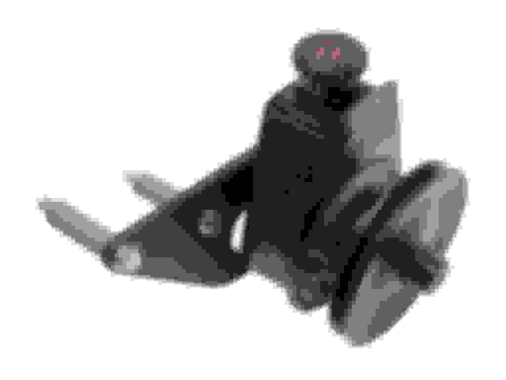
P-series Saginaw PS pump (add 2nd return for hydroboost)
This particular adventure stared out with the purchase of the Borgeson P/S Pump upgrade for Ford FE 390/428 engines. This upgrade comes with a Saginaw P-series pump that has one low pressure return line fitting just like the stock unit. It looks like this:
Subsequently, I encountered a fitment issue between the tall valve covers and the vacuum power brake booster and chose to address that with the installation of a hydroboost system from Hydratech.
Although most hydroboost conversions are content to use a "T" to join the low pressure return lines right before the reservoir, this can produce backpressure that causes a brake self-apply condition. I want to avoid that possibility if I can.
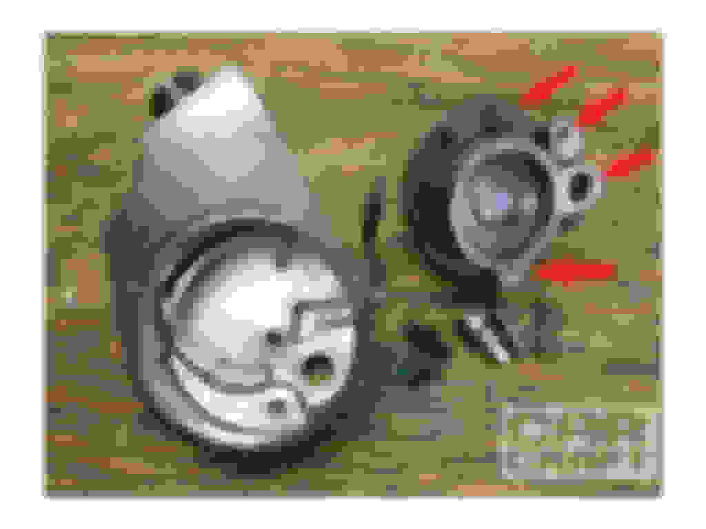
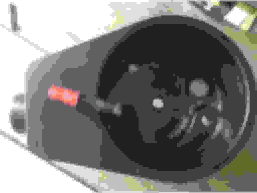
So here's the question. What are good ways to get two return line fittings for this brand new Saginaw pump? The reservoir can be removed (or replaced) like this:
Instructions: ... Remove Both Bolts On The Back Side Of The Reservoir And Remove The Large, High Pressure Fitting From The Rear Of The Pump. Then, Mount The Pump In A Vise Using The Flat Portion Of The Shaft Housing. The Housing Is Press Fitted Over The Pump, And A Few Whacks With A Large Rubber Mallet Will Drive The Reservoir Off The Pump Body. This Will Expose The One Large And Three Smaller O Ring Seals (arrows) ...
Of course AN fittings aren't strictly necessary with low pressure lines but it does look neater than overtightened hose clamps.
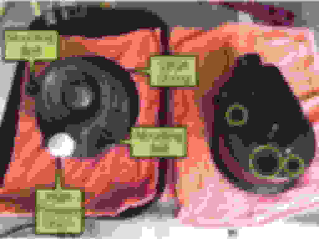
Here's an image showing how someone has actually done this albeit on a different kind of pump:
Where to place these bulkhead fittings seems an important question since I'd want to avoid aeration and foaming. How to place them is another question. I have only a picture of the inside of the reservoir and that seems to show that the return line doesn't simply exit/dump into the reservoir. There seems to be a guided channel in the body of the reservoir.
So if anyone here has done this or anything close to it, please share your experiences.
I put that question to the Hydratech people but no response yet. I did so b/c that seemed a reasonable tactic to me.
In my experience of searching on the threads on FTE, nobody has had that same issue with the brakes self-applying. I'm not saying it's never happened, just saying I haven't come across it in the countless threads I've searched.
Some have reported that their pedal was down a couple inches and wouldn't return to the top, but that doesn't necessarily mean that they were experiencing the same problem from this thread: brake self-apply condition.
If you read through the thread, the solution came when the gentleman having the problem completely eliminated the cooler (from what I can tell at least). Since the cooler was the issue with restricting the flow, the other gentleman from this thread: brake self-apply condition simply removed the cooler completely and returned the low pressure line directly to the pump? Am I understanding this correctly?
Alternatively... Instead of installing a Borgeson P/S Pump, why not go with the same pump that the Superduty's used? It's the same C-II pump with the additional return fitting in the housing.
Unless there's something I'm missing, the canned-ham power steering pumps are indeed better than the C-II Ford pumps. But why not just use the "right tool for the job" methodology and install a 99-04 C-II superduty pump? What's the big benefit of a different pump?
According to Hydratech, 98% of the people who correctly use a "T" fitting to join both low pressure returns do not experience any issues. The two most common errors are placement and orientation of the "T" fitting and use of a fluid cooler on the PS line that restricts flow. They also say that the optimal solution is to have and use two return line ports.
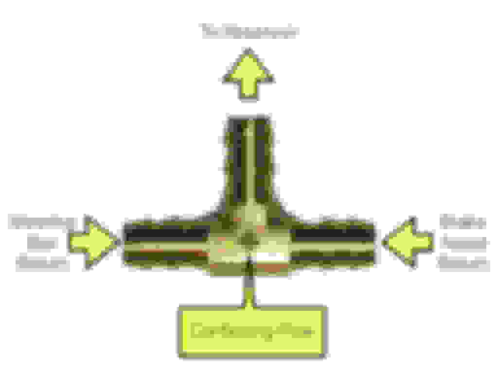
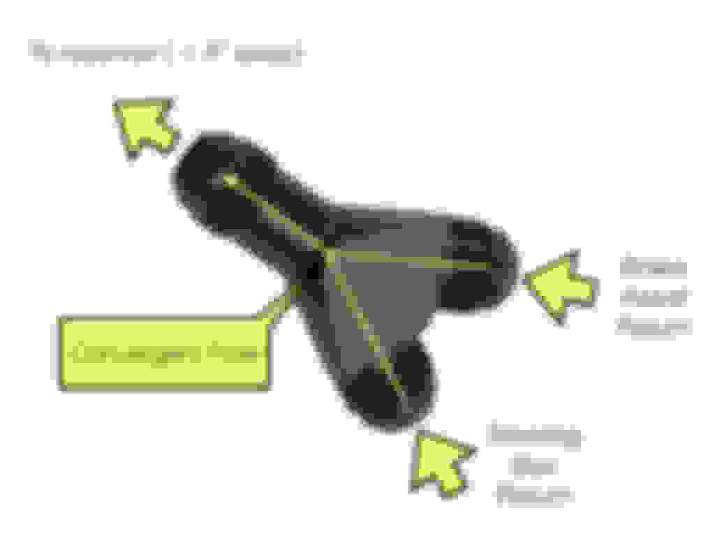
1) The "T" fitting needs to be very close to the reservoir and the connections to it need to avoid creating unnecessary turbulence. Here's a diagram:
2) Coolers often have internal structures (turbulators) designed to cause fluids to slow down to enhance the cooling effect of the fins so even if you are cooling only the PS return, the slowdown could increase pressure. Only 2-3 psi is needed to cause problems. This is why Hydratech recommends using passthru transmission coolers with the "T" fitting. For the same reasons check valves won't prevent upstream pressure caused by fluids that can't move through the return lines fast enough.
That 98% is encouraging but there are people who report various degrees of the self apply phenomenon. It's not clear from these reports whether some or all of these folks didn't make one or more of those common errors.
Since I'm already invested in Borgeson's FE PS conversion which includes the Saginaw pump with one return port, my options are more limited than someone who is just starting to work with their drawing table. Those options seem to be:
Take my chances with the "T" making sure I avoid the common errors
Modify the Saginaw reservoir
Purchase a new Saginaw pump specifically designed for hydroboost.
The third option isn't as appealing as the first two. I could start out with the "T" and see if I'm in that 98% group and then move to modifying the canned ham tin if not. Inded, I could probably source just the reservoir part and practice on it.
I would go to the jy and buy a used Saginaw ps pump that has the 2 return lines. Doesn't matter if the pump is still good because you only want the reservoir. Bring it home and clean well. Problem solved for cheap. I got mine from a 70's Lincoln.
I would go to the jy and buy a used Saginaw ps pump that has the 2 return lines. Doesn't matter if the pump is still good because you only want the reservoir. Bring it home and clean well. Problem solved for cheap. I got mine from a 70's Lincoln.
I like the idea of having expendable parts to experiment with.
My pump already had two return fittings but were of the slip on variety. Those things are notorious for leaking and I hate leaks. Removed the tank as per your earlier post, cut a piece of pipe the correct length to support the inside of the tank when clamped pump opening down on your work table. Obtain the correct AN fittings and slowly weld them in to keep warping to a minimum. Worked like a champ for me.
My earlier diagrams were not as clear as I would like so here are some replacements and additions that I hope make the single return option clearer.
This more clearly shows the condition to be avoided.
This being the preferred approach using a standard "T" fitting. However, one other option occurred to me as I thumbed through the Russell catalog.
Although this is an AN fitting which would require modifying a single return reservoir, it does offer a much less turbulent flow. I hope that this is more helpful.
Implementing Dual AN Returns (Saginaw P-series PS Pump)
After noodling over the various options, I chose to go with dual AN fittings so ordered two Russell Fuel Cell Bulkhead Adapter Fittings from Summit. Since I�ll be using a fair amount of braided SS lines for other things in the engine compartment, this will be in concert with the overall design. Beyond the aesthetics, there is the practical fact that dual return lines are best in a hydroboost conversion like this. Dual returns will reduce uncertainty.
The reservoir is easily separated from the pump body. Just remove the two mounting bolts and the high pressure union then tap the reservoir with a rubber hammer in several places to unseat it from the large o-ring that seals the border between pump and reservoir. Since this is a new pump, I will re-use all four of the O-rings during reassembly.
The pump body is then wrapped up and put away for reassembly later on after the reservoir mods have been completed.
The stock return lines on these pumps vary in shape and location. The one supplied with Borgeson�s FE PS upgrade is located in the center and sticks straight out to the rear. It is swedged on the inside and brazed on the outside. Thus the first step is to remove the stock return and enlarge this hole to 0.55� for the bulkhead fitting.
I simply put the return line in the vice and drilled it out from the back. There is still a lot of material to remove from the brazing and the swedge.
The mounting surface for the bulkhead fitting needs to be as flat and uniform as possible for optimal sealing so a good bit of time was spent on making the surrounding area flat after the hole was enlarged to 0.55� to accommodate the bulkhead fitting.
The same was done on the inside. This will replace the original return. Next up is locating and fabricating a hole for the second return. Once I have both holes made and finished, I will repaint the reservoir satin black.
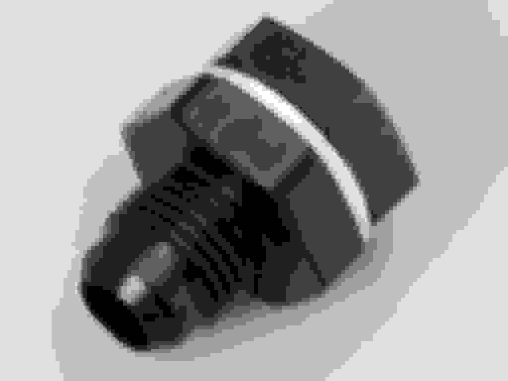
Here are the parts of the bulkhead fitting. The washers appear to be made of teflon or some kind of compressible plastic.
After a coat of light gray primer, I mocked-up the reservoir to survey potential locations for the second return.
A pencil tracing shows how the mounting bracket precludes many otherwise attractive locations. I decided to place the second return on the side of the reservoir because this location provides the most direct path to the PS fluid cooler from which the PS return fluid will come. One also has to be concerned about avoiding those parts of the pump that rise to the outer surface of the reservoir (see arrows). Each of these holes matches an O-ring on the pump body.
So YMMV even though you might also be using a Saginaw P-series pump. The brackets and stock return locations on your pump may dictate an entirely different approach.
Here is that path. The PS return from the steering box will go to the lower AN-6 port on the fluid cooler, exit the upper port and proceed to the AN-6 return port on the side of the power steering pump reservoir. The return from the hydroboost unit will go to the AN-6 port at the center of the rear of the reservoir.
Here�s the reservoir with a final coat of satin black and the two AN-6 bulkhead fittings tightened in place with a few dabs of Loctite blue on the threads.
The key to reassembly is matching the three small O-rings that secure the two mounting bolt holes and the high pressure union port as well as the large O-ring that secures the border between the pump body and the reservoir. There are several parts to the high pressure union that need to be returned in the same order and orientation as before.
I used the mounting bolts and a stack of extra washers to gently press the reservoir over the big O-ring before attempting to replace the high pressure union. These are metric bolts requiring a 17mm wrench.
So here it is mounted on the Borgeson bracket for this conversion and waiting for the plumber (me) to come and fab the necessary SS braided lines. I will have to develop some expertise with both high and low pressure braided SS lines since I have almost zero experience at this point. I�ve studied the instructions on the Russell web site and it seems to be a fairly straightforward process.
For reference for anyone....and not taking away from this thread.
There is a place in MN that sells just the reservoir with dual return lines for $40 and are brand new. That’s what I did. I bought a rebuilt kit for the pump for $18 and took a spare pump I had laying around and put it all together. Was real easy to do. I did a complete write up on it with pic’s in my pump rebuild.
The other option and a little harder to find is a pump that already has the dual return line set up. I just picked up a spare mid 70’s Ford 460 out of a LTD and the pump was still on it and had the Saginaw pump with the dual return lines on it. I’m going to keep that one for a spare.
You guys are overthinking this. The convergent flow tee in your pic works fine in everything I've put together.What can be a slight problem is too much or too little pressure the way the pump was delivered. which is easily corrected with the Borgeson pressure relief kit.Some nice low pressure hydraulic hose and some oetiker or wire spring clamps make the assembly look somewhat original. The orig 2 return cans are nice but sometimes the fittings can be in a bad spot for a nice assembly.

 05-25-2017, 12:16 PM