


113 things to know about a stock 7.3L PSD @ WOT!!!
Thread Starter
|
Postmaster
Joined: Jun 2006
Posts: 2,647
Likes: 0
From: Fulltime RVer

113 things to know about a stock 7.3L PSD @ WOT!!!
Since it's Friday the 13th I figure the safest way to get through the day is to remain in my easy chair and post 13 plus 100 more things about a stock 7.3L PSD doing a WOT run on a load dyno! Several months ago I came across this chart... http://ernesteugene.com/PSD/FEHPChart.jpg ...which already has the correct 250 FWHP output filled in so I decided to calculate the missing numbers for a stock 7.3L PSD. Well that became a several month effort which required building a new improved computer model but here's those missing numbers... http://ernesteugene.com/PSD/FEHP3.jpg ! The astute observer will notice that my numbers add up to a 679.9 hp output for a 679.7 hp input ...and that's how some accountants make extra profit by pocketing the "rounding errors" on their thousands of transactions!
As you can see in this pie chart... http://ernesteugene.com/PSD/Stock_Pie.jpg ...in my new model I lump the 3 lower terms in the previous chart together as FAHPL=Friction Accessories HP Loss because they all increase "nonlinearly" with engine rpm and they're all combined in the measured data I found in my engine textbooks.
The 113 things I promised appear as 113 numbered line items in these 3 tables... http://ernesteugene.com/PSD/Stock_Input.jpg ... http://ernesteugene.com/PSD/Stock_Output1.jpg ... http://ernesteugene.com/PSD/Stock_Output2.jpg ...and I also put together these graphs which are easier on the eyes... http://ernesteugene.com/PSD/Stock_FEHP.jpg ... http://ernesteugene.com/PSD/Stock_FEHP2.jpg ... http://ernesteugene.com/PSD/Stock_EGT.jpg ... http://ernesteugene.com/PSD/Stock_VFF.jpg ... http://ernesteugene.com/PSD/Stock_VFF2.jpg ... http://ernesteugene.com/PSD/Stock_AFR.jpg ... http://ernesteugene.com/PSD/Stock_EBP.jpg ... http://ernesteugene.com/PSD/Stock_BSFC.jpg ...
My next project is to use my new model to analyze the performance of these 2 wastegate mods... http://ernesteugene.com/PSD/WGMods.jpg ...and hopefully someone with a stock tune and a EGT gauge will try these mods and report their results. I did mod #2 years ago when trouble shooting my wastegate control system and with my 70-hp Superchip I could only make a maximum boost of about a BP=17 psig when the wastegate actuator was connected directly to the spider. With stock fueling I'm guessing that mod #2 will limit the maximum boost to about BP=12 psig ...and that with mod #1 the maximum boost will be about BP=22 psig.
So for starters I'm going to run my model with the same VFF gph vs RPM stock fueling curve used in the above runs with BP=17 psig and the only changes are to assume that with mod #1 the wastegate remains completely closed and allows a BP=22 psig and that with mod #2 the wastegate opens far enough to limit the boost to BP=12 psig. So does anyone want to predict what happens to the FWHP output for mod #1 vs mod #2 vs stock for the same VFF input? I know the answer for a previous run but that was before I updated my model to include the variation of TE with AFR and there's an increase in efficiency at higher AFR due to less combustion heat loss to the coolant.
Gone Fishin for Mark
Joined: Nov 2004
Posts: 1,354
Likes: 2
From: West of Houston

And I will supply your beer!!!

Duct Tape Tech.
Joined: Jul 2009
Posts: 2,381
Likes: 1
From: San Antonio Tx.
Free Beer!
Trending Topics
PREMIUM SPONSOR


Joined: Feb 2009
Posts: 6,037
Likes: 73
When do we need to be there Rick? I need some lead time...
FTE Stories
Ford Trucks for Ford Truck Enthusiasts

10 Best Ford Truck Engines We Miss the Most!
Joe Kucinski
2026 Shelby F-150 Off-Road: Better Than a Raptor R?
Brett Foote
2027 Super Duty Carhartt Package First Look: 12 Things You NEED to Know!
Michael S. Palmer
10 Most Surprising 2026 Ford Truck Features!
Joe Kucinski
Top 10 Ford Trucks Coming to Mecum Indy 2026
Brett Foote
5 Best / 5 Worst Ford Truck Wheels of All Time
Joe Kucinski
Ford Super Duty: 5 Things Owners LOVE, 5 Things They LOATHE!
Joe Kucinski
Every 2026 Ford Truck Engine RANKED from WORST to FIRST!
Michael S. Palmer
The Best F-150 Deal of Every Trim Level (XL through Raptor)
Joe KucinskiPost Fiend
Joined: Feb 2006
Posts: 11,892
Likes: 2
From: Middle Tennessee
Good to hear from you Gene and I hope all is well. I don't have time to really look at the data but I will try, hopefully in a week or so. I have a whole lot going on right now. Again, always good to see you posting. You have good viewpoints and valuable analysis.

Thread Starter
|
Postmaster
Joined: Jun 2006
Posts: 2,647
Likes: 0
From: Fulltime RVer
...So for starters I'm going to run my model with the same VFF gph vs RPM stock fueling curve used in the above runs with BP=17 psig and the only changes are to assume that with mod #1 the wastegate remains completely closed and allows a BP=22 psig and that with mod #2 the wastegate opens far enough to limit the boost to BP=12 psig. So does anyone want to predict what happens to the FWHP output for mod #1 vs mod #2 vs stock for the same VFF input? I know the answer for a previous run but that was before I updated my model to include the variation of TE with AFR and there's an increase in efficiency at higher AFR due to less combustion heat loss to the coolant...
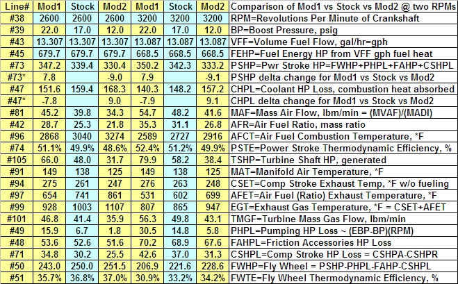
Lines 73* & 47* above show that the gains in PSHP with higher BP occur because the CHPL=Coolant HP Loss (which is caused by combustion heat being absorbed by the cylinder during the power stroke) is lower by the same amount as the gains in PSHP ...and the following lines show that this happens because a higher BP causes a higher MAF which causes a higher AFR which causes a lower AFCT=Air Fuel Combustion Temperature which causes less combustion heat to be lost during the power stroke time interval which at a given RPM is the same time interval for each BP value ...and this explains the higher PSTE=Power Stroke Thermodynamic Efficiency for higher BP shown in line #74!
However the rest of the story begins with the next line which shows that a larger TSHP=Turbine Shaft HP needs to be generated in order to sustain a higher BP and that even though the MAT is higher at higher BP the lower AFET=Air Fuel (Ratio) Exhaust Temperature causes a lower EGT and this means the larger TSHP must be generated by a larger TMGF=Turbine Mass Gas Flow at a lower EGT and that can only be done with a larger EBP relative to the BP which results in the larger PHPL=Pumping HP Loss in line #49. The higher BP pressure loading also causes an increase in friction forces which results in a slightly larger FAHPL=Friction Accessories HP Loss ...and compressing all that extra MAF causes a larger CSHPL=Compression Stroke HP Loss ...and the bottom-line is a... FWHP=PSHP-PHPL-FAHP-CSHPL ...that's lower at higher BP resulting in a lower FWTE=Fly Wheel Thermodynamic Efficiency even though the PSHP and PSTE are higher at higher BP!
Check out these graphs which tell the complete story... http://ernesteugene.com/PSD/WG_EGT.jpg ... http://ernesteugene.com/PSD/WG_HPdelta.jpg ... http://ernesteugene.com/PSD/WG_VFF.jpg ...and note the data point in this graph... http://ernesteugene.com/PSD/WG_BSFC.jpg ...which is from the factory dyno sheet on my C7 because it shows that Mod1 (which produces an AFR=28.0 at 2200 RPM) is about how much my C7 is "over boosted" in order to meet the 2003 NOx emissions spec!
Here's some more charts for those who enjoy finding "Waldo" on placements... http://ernesteugene.com/PSD/WG_Output1.jpg ... http://ernesteugene.com/PSD/WG_Output2.jpg

Thread
Thread Starter
Forum
Replies
Last Post
ernesteugene
6.7L Power Stroke Diesel
12
May 10, 2013 06:06 PM
ernesteugene
1999 - 2003 7.3L Power Stroke Diesel
16
May 18, 2010 01:03 PM
ernesteugene
1999 - 2003 7.3L Power Stroke Diesel
20
May 28, 2008 11:26 AM
ernesteugene
1999 - 2003 7.3L Power Stroke Diesel
25
Jul 31, 2007 08:15 PM