When you click on links to various merchants on this site and make a purchase, this can result in this site earning a commission. Affiliate programs and affiliations include, but are not limited to, the eBay Partner Network.
The clean-up and painting of the rearmost part of the frame is best done after removing the axles and springs. At this point, the fuel and brake lines plus all wiring in this area have also been removed. When done I will have a clean workspace.
Taking this approach will also require me to pay close attention to all of these components before replacing them. Who knows what ideas and issues will emerge.
The drive shaft and emergency brake linkage had already been removed so all I had to do is remove the nuts to the U-bolts, raise the chassis a few inches and then roll the rear axle out on the vehicle dollies that I�ve been using to move the truck around in the shop.
The springs come off by removing two 7/8� bolts per side.
Initially, I used pair of antique screw jacks that I had just finished restoring but they proved to be a little too wobbly for me to feel OK about getting under it. They may be better than a hydraulic jack which can leak down on you but they cannot beat a modern jack stand. Safety first.
Compared with the F-100 of the same year (�76), the F-150 springs have an auxiliary spring raised an inch or so by a cast iron spacer. This aux spring doesn�t do anything until the regular springs are significantly compressed. There are special riveted tabs on the frame that engage this aux spring as needed. There is also an extra HD spring added to the bottom of the spring bundle. These extras are where much of the GVR differences between the F-100 and F-150 apparently come from.
I will need to research whether these extras are compatible with this truck�s new mission. It will have a Class III trailer hitch/receiver but any really heavy lifting will probably be left to the F-350.
Wheels removed, the rear axle will sit outside on jack stands getting an occasional scrubbing from rainfall. I�m inclined to keep the housing but replace the third member and axles. I�m thinking 3.70 (up from 3.25) with TrueTrack or WaveTrack (up from limited slip clutches). Keeping the drum brakes versus a disc brake conversion will also be an interesting debate.
So the frame is bare and ready for cleaning and painting. Note the use of jack stands and substantial blocks. Rock steady, that enables me to safely remove the dirt and rust. Painting the cleaned-up frame will set the stage for installing the new fuel tank and running the new fuel lines etc.
Problem is, I don't think there's another 5x5.5" disc brake pattern stock from Ford. Maybe a later Dodge system could be used, not sure if there's a bracket that can be used on a Ford rear end.
A bracket for using the Dodge calipers on a Ford rear would be a cool deal if no one is already making one.
In most cases, there is a drum system on the inside of the rotor hat. IIRC that's the way the Explorer works and maybe the old 5x5 Lincoln.
Problem is, I don't think there's another 5x5.5" disc brake pattern stock from Ford. ... In most cases, there is a drum system on the inside of the rotor hat. IIRC that's the way the Explorer works and maybe the old 5x5 Lincoln.
Yes, I believe that you are correct which means that one would have to look to aftermarket suppliers to fulfill the desire for disc brakes on the rear of a dent side truck using the stock bolt circle. I did find a vendor offering a $600 kit (Western Chassis) that seemed to fit the bill but they state that it's for 1948-72. It will work on a bump but not on a dent. Does that sound right? I have written to them asking that.
I then spent some time on the Currie web site and found this:
CE-6011WT - Wilwood Disc Brake Kit w/ Internal E-Brake - 11" Rotors (Late LB) Wilwood Disc Brake Kit w/ Internal E-Brake - 11" Rotors (Late LB)
SKU: CE-6011WT $745.95
Wilwood 11" diameter rotor disc brake kit features vented rotors, forged aluminum 4-piston black anodized calipers with pads, caliper mounting bracketry that is also the mounting for the internal drum style parking brake assembly, and your choice of wheel bolt pattern and wheel stud hole size. This kit will only fit the late model large bearing housing ends and axles with a 2.500" brake space offset.
So I guess that I need to do some measuring to determine whether my 9" rear axle has the late model large bearing housing ends and axles with the required offset. Of course Currie would be happy to sell me a brand new housing. Also, the eBrake linkage (Lokar) is extra and I suppose that te eBrake drum etc. is also extra though I couldn't find a listing for it.
Thanks. I did that and found TSM Disc Brakes who offer a 9 inch Ford 1957 to 1986 Complete Rear Disc Brake Kit in two varieties:3/8 inch backing plate bolts and 1/2 inch backing plate bolts for about $700.
The images and descriptions were a bit fuzzy so I've written to them asking for a copy of the installation instructions. Short of having the product in hand, I find that the installation instructions often convey a good bit of usable information.
1973-79 Ford F100 & F150 5 X 5.5 in either 3/8� or 1/2� axle flange bolts. $799.95
Rear Disc Brake Conversion Kit converts rear drums to 11-5/8" rotors with single piston calipers equipped with integrated emergency brake. Simply reuse your existing emergency brake cables. Rear disc brakes improve your truck's braking system and provide reliable, all-weather performance. Kits are available with either standard or cross drilled/slotted rotors for better performance, longer life and cooler braking temperatures.
Fits models with Ford 9" rear end only. Rear Disc Brake Conversion Kit will work with 15" or larger wheels. Disc Brake Combination Valve #37-8546 is required. Requires fabrication of new rear brake lines.
Kit contains 11-5/8" standard or performance cross drilled/slotted rotors, single piston calipers with semi-metallic brake pads, brake hoses, mounting brackets and hardware, and detailed instructions.
I liked the fact that you can re-use the stock eBrake cables. It looks like the slotted, cross-drilled rotors are $100 extra.
Well, good sir I am greatly impressed by your wealth of knowledge and I am local to you. Can I buy you a cup of coffee and pick your brain for some of this tremendous wisdom. I know my 73 dent in retrospec would greatly appreciate it.
Well, good sir I am greatly impressed by your wealth of knowledge and I am local to you. Can I buy you a cup of coffee and pick your brain for some of this tremendous wisdom. I know my 73 dent in retrospec would greatly appreciate it.
The rear part of the frame (behind the cab, formerly under the bed) is now ready for clean-up and paint. That operation will set the stage for installing a new fuel line and fuel tank.
Here is the rear of the frame stripped of bed, gas tank, fuel lines, brake lines, wiring, springs and rear axle. It is now ready for clean-up.
I must have scraped five or ten pounds of rust and dirt from this part of the frame. Fortunately, it�s been rather cool here in the middle of Georgia so I was able to wear protective gear somewhat comfortably. The hardest part was working overhead while laying on a creeper. Tools seem to gain weight when one is in this position. Still, �I got her done.�
This took almost three rattle cans of Canyon Black. There is a lot of surface area on a frame it seems.
Here�s another angle.
Disassembling the springs reveals a lot of rust and dirt that will have to go. As well, some of the spring leaves themselves may have to be set aside.
A few hours of work with a rotary wire brush removed most of the rust and dirt. The leaf most likely to be excluded is the fat one found at the bottom of the spring pack. An F-100 of the same year (�76) will not have this spring.
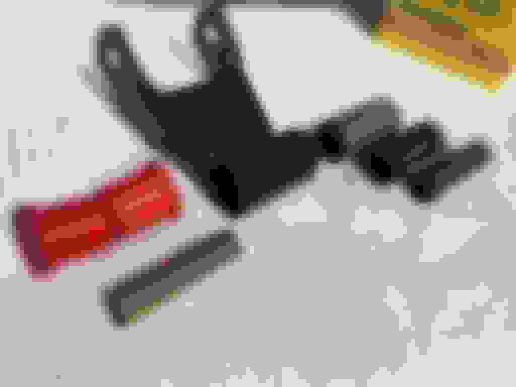
In order to replace the old, worn-out stock bushings with polyurethane units from Energy Suspension, one has to remove three components of the old system. I found that the innermost sleeve could be driven out with the round head of a ball peen hammer used as a drift (it centers nicely) followed by a more conventional drift pin. The rubber sleeve and outer steel sleeve needed to be split with reciprocating saws before they could be driven out. The last step of this prep is to use emery paper and a little oil to remove rust and smooth the way for the new polyurethane bushings.
A bit of paint will keep the rust away for a while
Using the supplied lube, the polyurethane bushings are easily installed by hand. The metal bushings, on the other hand, need to be pressed in. I used a big C-clamp.
There are three bushings for each spring set. Here, you can see the main leaf plus the rear hanger.
The main leaf package now has only four leaves because I have omitted the short fat spring at the bottom which is one of the things that differentiates an F-150 from an F-100 for this year (�76).
The rear hangar is loosely attached. I duplicated the orientation of the bolts which I suppose is to assure proper clearance.
Not shown in this image is the elevated secondary spring that is only active when the main spring set is significantly compressed. This temporary installation will keep these parts safe and out of the way as I attack the second set of springs.
Not using the big F-150 specific spring makes the bolt that secures and centers the spring pack a bit too long.
This is the spacer that separates the lone helper spring which has a button located in this hole which is currently preempted by the aforementioned bolt.
The extra helper spring doesn�t locate well because of the length of the spring pack bolt. The extra spring that I�ll not be using is on the floor.
The extra helper spring engages plastic pads attached to these perches.
The passenger side springs are finished to the same point as the driver side. Here, we see the auxiliary spring atop the cast iron spacer and under the U-bolt plate.
I will not be shortening the center bolt until I have resolved the question of what to put between the leaves if anything. I am currently looking to source UHMW plastic that is 2.5� wide and 0.060� thick in lengths of 120� or more. Three of those would add 3/16� to the main spring pack and obviate the need to shorten the center bolt. I did find one supplier who quoted a price just shy of $60 but the shipping would be $350! So, still looking
UHMW is Ultra-high-molecular-weight polyethylene. This is a very tough material, with the highest impact strength of any thermoplastic presently made. This stuff seems to be very popular with off-roaders whose vehicles use leaf springs.

 03-23-2018, 06:32 PM