Auto-Lamp System Retrofit for Truck Use
By Ford-Trucks Community Member: LCAM-01XA
Ya’ll know how on many new cars and trucks when you shut the engine off and exit the vehicle the headlights and sometimes the interior lights stay on for some time to illuminate your way to the house, then automatically shut off? Well most of our trucks don’t have that, but many Ford passenger cars do – I installed an ’89 Crown Victoria delayed-exit light modules in my ’90 truck, and now my headlights stay lit for a full minute after engine has been shut off.
Coincidentally, the same module also has a photocell in it and can be used for automatically operating the headlights – I didn’t use this feature as I didn’t really feel like messing with the associated wiring and I like manual control of my (way too powerful) lights anyways, but if you wanted to run automatic lights in addition to the delayed-exit, and also be able turn the system on/off, this is how to wire the thing up (diagram courtesy of an English gentleman by the name of Dereck who installed this in his Excursion):
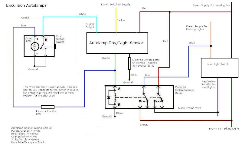
Basically the switch in the left side is your on/off switch for the system, the autolamp sensor is the factory Ford control module, the stuff below the sensor is a DPDT relay (one control circuits triggers two independent power circuits at the same time), and on the right you have your factory headlights switch. What happens is that when the ignition is on and you on/off switch is also on the autolamp sensor will bypass the headlights switch and power up the lights independently of it, so if it’s dark out there and you want your lights off while running the engine you have to use your on/off switch to shut the the autolamp sensor off, and if you want headlights during daytime (the autolamp sensor will not turn them on when there ambient lighting is good) you use your factory ignition switch. The autolamp sensor will obviously need to be installed in a location where it can "see" daylight good, the factory drills a hole in the dash pad and puts it under there so light can fall through that hole and onto the photocell.
As far as the relay goes you have two options:
- If you want both your headlights and marker lights to be controlled by the autolamp sensor you either install a DPDT relay like in the diagram, or you just run two regular cheap SPST relays in parallel where you splice the sensor output wire (green in the diagram) into two separate wires so it triggers both relays at the same time;
- If you only want the headlights to be controlled by the autolamp system just run a single SPST relay for the headlights circuit and don’t worry about the blue and brown wires in the diagram that are used for the marker lights.
An important note on this: your gauge cluster illumination is tied into the marker lights circuit, so if you use the autolamp system to only power up the headlights your gauges will not light up unless you manually turn the marker lights on with the factory headlights switch.
Now onto the delay-exit lights – the factory uses a variable resistor to control the time the lights stay on after ignition is shut off, that variable resistor (along with the system on/off switch really) is integrated in the main headlights switch which looks like it could made to fit our trucks but may require some grinding on the plastic panel of the dash. If you would like adjustable time delay, but do not want to mess with retrofitting headlight switches, you can run an external variable pod like you can buy in RadioShack. For sake of simplicity both Dereck and I have chosen to run a fixed time delay, he opted for the 54k-ohm resistor that you see in the diagram and that gives him about 30 seconds of delay, while I installed a 100k-ohms resistor in my truck and my lights stay on for about a minute. As you probably figured it by now, there is a small capacitor inside the autolamp sensor, and its discharge rate depends in that external resistance – the larger the resistance the slower the discharge and so the longer the time delay, and this will take some experimentation on your part to find the exact resistance that makes your lights stay on for the amount of time you want them on.
The way all this is installed in my truck – I have converted my low beams to DRL mode (they are on all the time the truck is running), so I did not really need the autolamp feature of the control module, which allowed me to lose the on/off switch and also to install the control module inside the engine bay where it "sees" dark all the time – basically the system is always active when the ignition is on, and it also keeps the DRLs lit regardless of ambient lighting conditions. This greatly simplifies the install – the white wire that in the diagram goes to the on/off switch now gets grounded instead, and the sensor itself get spliced in my key-on trigger for the SPST relay I already installed for the DRLs so that the key-on 12V go into the sensor through its yellow wire, and then out the sensor and to the DRL relay through the green wire. Piece of cake really, and works awesome!
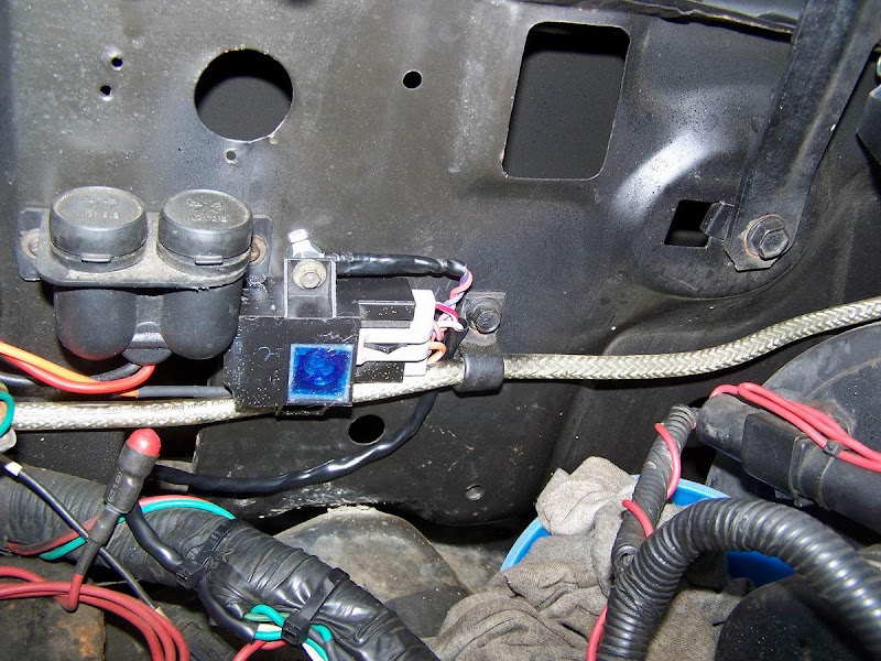
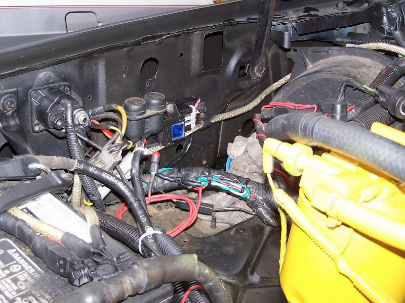
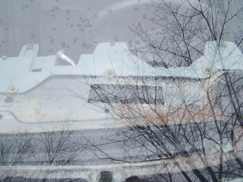
And here are the pictures – this is where the sensor is right now in my truck:
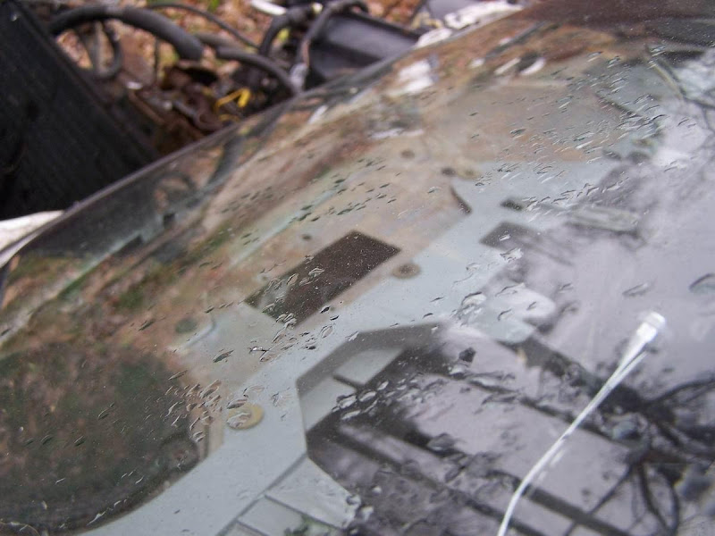
And this is where it came from in the box-body Crown Vic, that hole in the sheetmetal above the gauge cluster (you need to remove the dashpad to get to it tho, lots of #2 philips screws):
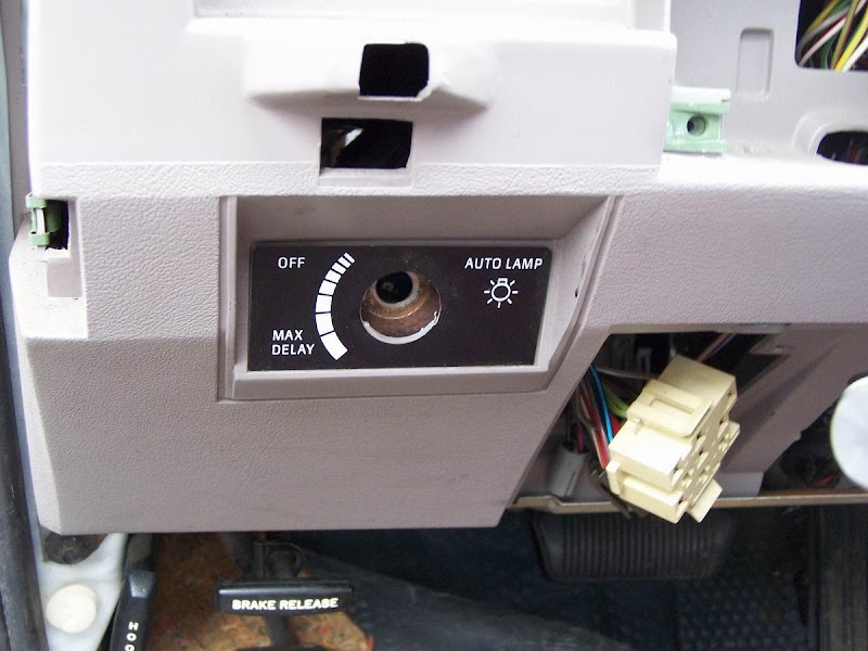
I do not have the exact Ford part number for the sensor, and I’m sure it changed a few times through the years anyways, but many (not all tho) Ford Crown Victoria, Mercury Grand Marquis, and Lincoln TownCar vehicles from the late-’80s will have that system, it’s easiest identifiable by the extra collar around the headlights switch know – basically if you see this you got the right car:
To make install easier it’s best that you take the sensor and some of the wiring, then splice and extend as needed. To make this work as a delayed-exit system only he wiring is as follows, colors are the actual ones on the pigtail:
- Purple wire with orange tracer – ground it
- Red wire with yellow tracer – give it 12V key-on
- Orange wire with white tracer – give it 12V constant (battery)
- White (sometimes looks like salmon) wire with purple tracer – this is your headlights relay trigger
- Bluish wire with orange tracer – attach your resistor to that, then ground it.
Also it must be noted the sensor was not designed to live in an environment where it can get wet, so a silicone sealer treatment may be a good idea, I sealed every single gap and crack in my sensor except the access opening for the adjustment wheel inside it, but that’s on the bottom of the sensor as I have it installed. Additionally, if you were to use the auto-lamp feature of the module, you cannot have it under the hood, instead it needs to go in a place where it can "see" ambient light.