
My lifted 2WD F250

#227
 11-08-2011, 12:54 PM
Lead Driver
Spools are pretty much a dirt only truck thing IMO. Even on a race truck I'd rather run a locker or posi (set up super tight of course) if it's me. Posi is my 1st choice if it's available in whatever rear & axle size I'm running actually.
As for desert trucks having them - yeah many do. The high end trucks with them are race teams that have the $$ to replace the axles often.
I also see a lot of spools in the lower classes or race trucks, but often those guys are buying them because they are much cheaper than a locker. Many of those guys would back me up in saying spools are silly to have on a truck that sees much if any street time - which the truck in question does.
#228
11-08-2011, 01:45 PM
#230
03-12-2012, 07:07 PM
Join Date: Jan 2007
Location: Trabuco Canyon, SoCal
Posts: 547
Likes: 0
Received 0 Likes
on
0 Posts
here's a small video of my V10 SD. The red one is owned by Sage Carli, check out www.thecarlisuspension.com to see his line-up of systems. He's been heavily involved with the Dodge HD's, and has been slowly getting into the Ford's.
http://www.youtube.com/watch?feature...&v=ipppIts1I6Q
http://www.youtube.com/watch?feature...&v=ipppIts1I6Q
Last edited by 76Hauler; 03-12-2012 at 07:08 PM. Reason: video

#235
04-30-2012, 08:27 PM
#236
04-30-2012, 09:59 PM
Join Date: Jan 2007
Location: Trabuco Canyon, SoCal
Posts: 547
Likes: 0
Received 0 Likes
on
0 Posts
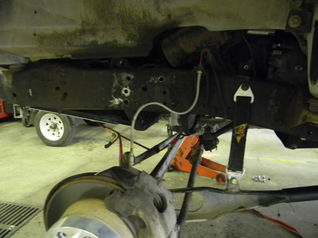
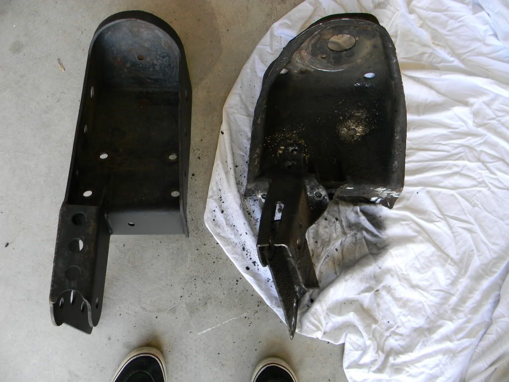
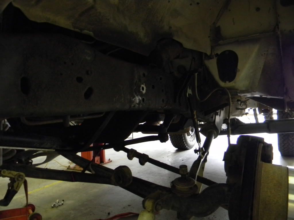
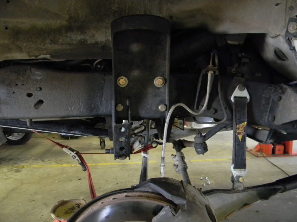
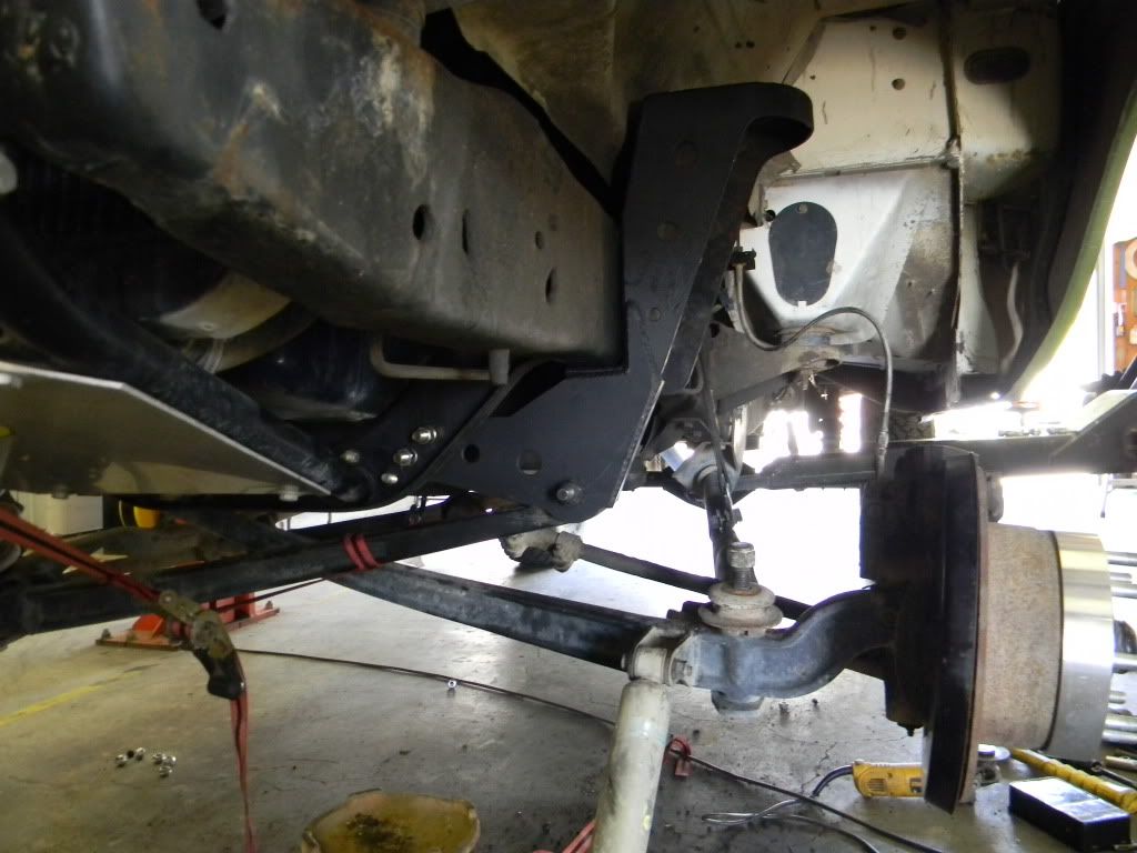
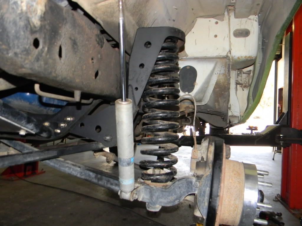
these are Autofabs one peice coil buckets. the design lets the end user have better shock options, meaning you can build a hoop for 1-2- even 4 shocks per wheel! I plan to use one 2.5" 14-16" stroke King or Bilstein shock w/ resi's. Plus, these towers are, I think, 2" taller, to allow a longer coil to be used, that lets the truck have more up travel for better bump control.
<!--msnavigation--><!--msnavigation--><TABLE dir=ltr border=0 cellSpacing=0 cellPadding=0 width="100%"><TBODY><TR><TD vAlign=top width="1%">Table of Contents
</TD><TD vAlign=top width=24></TD><!--msnavigation--><TD vAlign=top>Front wheel travel
What we do to get wheel travel.
There are numerous lift companys out there but Autofab is the only company to offer a 5 inch lift and 16" of front wheel travel for the 1965 to 1979 Ford 2WD twin I beam trucks. Up to 4 shocks per wheel custom hoop structures , fabricated coil spring buckets with optional coil height adjusters ! New pivot structures for the beams are fabricated then welded to the buckets. This is a bolt on kit of racing quality that you can install yourself, if you have reasonable mechanical skills!

This kit is shown with coil adjusters and reinforced radius arm options. Price $3450 exchange on beams and radius arms. This kit will work on F250 and F350 trucks as well from 1965 to 79. Add $200 for F250/350 kits. Optional mono ball and rod end joints on beams and radius arms. Call for current pricing on rod ends.
First we inspect the king pin end then straighten the I beam. We have a 100 ton press in our shop to accomplish this ! 90 percent of the time the beams are tweaked from hitting a curb or ditch and even previous bending at alignment shops. Their common practice is to bow the beam to correct minor camber changes.
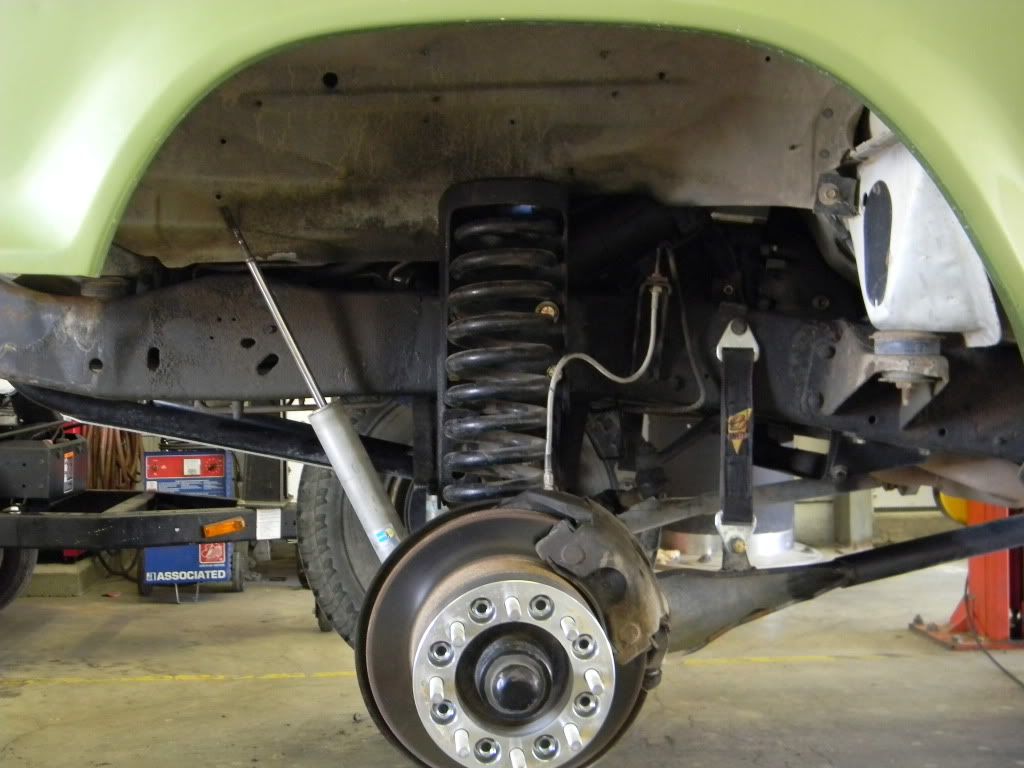
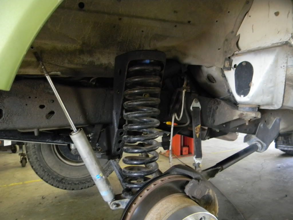
The beams are then aligned for the 4" of lift. This requires bending for camber and caster on each beam. The radius arms are then lengthened about a foot to allow the beam and spindle to droop further for more wheel travel. We fabricate our extensions from solid steel not just tubing because we want our radius arms to be stronger than stock. New threaded ends are installed on the radius arms at this time. New radius arm pivot brackets are fabricated to correct the bushing alignment and offset the radius arm in for more tire clearance. Also provisions for a crossmember are designed into the pivot brackets for you chassis guys.
To get wheel travel to work you need longer shocks and different mounts. Here is I discovered the problems of working with a stock coil bucket. It basically is in the way of good shock mounting ! This led to the development of our coil bucket complete with beam pivot brackets built in. Now we have plenty of room to put our longer travel shocks on the front and back side of the coil. With special shock mounts welded to the beam and the radius arms joined with custom hoops and shock mounts welded to the coil bucket, we have achieved 16" of wheel travel with stock steering components. Close attention is paid to correct shock geometry in our shock mounting , for longer life on bushing or heim ends of shocks
</TD></TR></TBODY></TABLE>
<!--msnavigation--><!--msnavigation--><TABLE dir=ltr border=0 cellSpacing=0 cellPadding=0 width="100%"><TBODY><TR><TD vAlign=top width="1%">Table of Contents
</TD><TD vAlign=top width=24></TD><!--msnavigation--><TD vAlign=top>Front wheel travel
What we do to get wheel travel.
There are numerous lift companys out there but Autofab is the only company to offer a 5 inch lift and 16" of front wheel travel for the 1965 to 1979 Ford 2WD twin I beam trucks. Up to 4 shocks per wheel custom hoop structures , fabricated coil spring buckets with optional coil height adjusters ! New pivot structures for the beams are fabricated then welded to the buckets. This is a bolt on kit of racing quality that you can install yourself, if you have reasonable mechanical skills!
This kit is shown with coil adjusters and reinforced radius arm options. Price $3450 exchange on beams and radius arms. This kit will work on F250 and F350 trucks as well from 1965 to 79. Add $200 for F250/350 kits. Optional mono ball and rod end joints on beams and radius arms. Call for current pricing on rod ends.
First we inspect the king pin end then straighten the I beam. We have a 100 ton press in our shop to accomplish this ! 90 percent of the time the beams are tweaked from hitting a curb or ditch and even previous bending at alignment shops. Their common practice is to bow the beam to correct minor camber changes.
The beams are then aligned for the 4" of lift. This requires bending for camber and caster on each beam. The radius arms are then lengthened about a foot to allow the beam and spindle to droop further for more wheel travel. We fabricate our extensions from solid steel not just tubing because we want our radius arms to be stronger than stock. New threaded ends are installed on the radius arms at this time. New radius arm pivot brackets are fabricated to correct the bushing alignment and offset the radius arm in for more tire clearance. Also provisions for a crossmember are designed into the pivot brackets for you chassis guys.
To get wheel travel to work you need longer shocks and different mounts. Here is I discovered the problems of working with a stock coil bucket. It basically is in the way of good shock mounting ! This led to the development of our coil bucket complete with beam pivot brackets built in. Now we have plenty of room to put our longer travel shocks on the front and back side of the coil. With special shock mounts welded to the beam and the radius arms joined with custom hoops and shock mounts welded to the coil bucket, we have achieved 16" of wheel travel with stock steering components. Close attention is paid to correct shock geometry in our shock mounting , for longer life on bushing or heim ends of shocks
</TD></TR></TBODY></TABLE>
#237
04-30-2012, 10:03 PM
Join Date: Jan 2007
Location: Trabuco Canyon, SoCal
Posts: 547
Likes: 0
Received 0 Likes
on
0 Posts
here is what I want to copy.......
<TABLE dir=ltr border=0 cellSpacing=0 cellPadding=0 width="100%"><TBODY><TR><TD vAlign=top>Equal Length Tie Rod system
The Ford twin I beam front end was introduced in 1965 on Ford 2wd trucks. The basic design remained unchanged until 1979. One of the most unusual features of the Ford 2wd truck is Rear steer. That means the steering and linkage is behind the front axle centerline. Ford used rear steer on many passenger cars as well. Ford produced many fast successful cars with rear steer. Early Mustangs, Fairlane, and Torinos are good examples. I think this was their reasoning back in the day for better steering geometry. The idea is this: Picture the front suspension looking down from the top. Draw an imaginary line from the center of the steering axis through the center of the tie rod hole and project it until the 2 lines left and right intersect in the rear. That is the center of the rear axle. This is how Ford decided where the steering arms needed to be. Also this is the primary reason you do not want to turn a rear steering spindle around when converting to a front steer. I have seen many done that way too, back when these trucks were the class 8 choice. I may cover that topic at a later date.
Why Ford did not try to create an equal length tie rod system remains a mystery. My guess is that it was considered, but economics dictated a Y style system. Obviously less complicated and cheaper to build regardless of the toe change problems. This is one of the reasons Ford trucks has a reputation of cupping front tires. You have a beam making a constant camber change and a Y style steering with toe change. When you really stop and think about it , This front end should not have worked at all! But time has proven otherwise. You really do not notice this driving a Ford and the changes that occur are within tolerable limits. Off road racing dictates a different steering system. There were just too many problems with steering tie rods bending from hard off road use. The position of the Ford steering gear box is pretty close to the inside beam pivot. By creating an idler arm to swing from the opposite beam pivot we accomplish our left side tie rod starting point. The primary complication to overcome is driving the idler. The simple method is creating a special pitman arm. The tie rod to the right wheel and the link to drive the idler arm both come off the pitman arm now. This all sounds easy enough until you start trying for some serious wheel travel. The tie rods have to go through the radius arm and there is only so much room to work with. Also we have to avoid the tie rods colliding with each other as well. The system we designed for the spare parts truck cycles correctly through up to 26 inches of wheel travel. We have almost totally eliminated the bump steer as a result. Here are some pictures of our system.
.jpg)
.jpg)


<!--msnavigation--></TD></TR><!--msnavigation--></TBODY></TABLE>
<!--msnavigation--><TABLE border=0 cellSpacing=0 cellPadding=0 width="100%"><TBODY><TR><TD>Send E-mail to john@autofab.com with questions or comments about this web site.
Last modified: August 17, 2011
</TD></TR><!--msnavigation--></TBODY></TABLE>

I'll just be doing this stages, as money does not want to hang out with me that much. Seems like cash likes to go were the wife and kids wanna go.<NOSCRIPT></NOSCRIPT>
<TABLE dir=ltr border=0 cellSpacing=0 cellPadding=0 width="100%"><TBODY><TR><TD vAlign=top>Equal Length Tie Rod system
The Ford twin I beam front end was introduced in 1965 on Ford 2wd trucks. The basic design remained unchanged until 1979. One of the most unusual features of the Ford 2wd truck is Rear steer. That means the steering and linkage is behind the front axle centerline. Ford used rear steer on many passenger cars as well. Ford produced many fast successful cars with rear steer. Early Mustangs, Fairlane, and Torinos are good examples. I think this was their reasoning back in the day for better steering geometry. The idea is this: Picture the front suspension looking down from the top. Draw an imaginary line from the center of the steering axis through the center of the tie rod hole and project it until the 2 lines left and right intersect in the rear. That is the center of the rear axle. This is how Ford decided where the steering arms needed to be. Also this is the primary reason you do not want to turn a rear steering spindle around when converting to a front steer. I have seen many done that way too, back when these trucks were the class 8 choice. I may cover that topic at a later date.
Why Ford did not try to create an equal length tie rod system remains a mystery. My guess is that it was considered, but economics dictated a Y style system. Obviously less complicated and cheaper to build regardless of the toe change problems. This is one of the reasons Ford trucks has a reputation of cupping front tires. You have a beam making a constant camber change and a Y style steering with toe change. When you really stop and think about it , This front end should not have worked at all! But time has proven otherwise. You really do not notice this driving a Ford and the changes that occur are within tolerable limits. Off road racing dictates a different steering system. There were just too many problems with steering tie rods bending from hard off road use. The position of the Ford steering gear box is pretty close to the inside beam pivot. By creating an idler arm to swing from the opposite beam pivot we accomplish our left side tie rod starting point. The primary complication to overcome is driving the idler. The simple method is creating a special pitman arm. The tie rod to the right wheel and the link to drive the idler arm both come off the pitman arm now. This all sounds easy enough until you start trying for some serious wheel travel. The tie rods have to go through the radius arm and there is only so much room to work with. Also we have to avoid the tie rods colliding with each other as well. The system we designed for the spare parts truck cycles correctly through up to 26 inches of wheel travel. We have almost totally eliminated the bump steer as a result. Here are some pictures of our system.
<!--msnavigation--></TD></TR><!--msnavigation--></TBODY></TABLE>
<!--msnavigation--><TABLE border=0 cellSpacing=0 cellPadding=0 width="100%"><TBODY><TR><TD>Send E-mail to john@autofab.com with questions or comments about this web site.
Last modified: August 17, 2011
</TD></TR><!--msnavigation--></TBODY></TABLE>
I'll just be doing this stages, as money does not want to hang out with me that much. Seems like cash likes to go were the wife and kids wanna go.<NOSCRIPT></NOSCRIPT>

#240
05-02-2012, 12:08 PM
Lead Driver
