When you click on links to various merchants on this site and make a purchase, this can result in this site earning a commission. Affiliate programs and affiliations include, but are not limited to, the eBay Partner Network.
Jolly
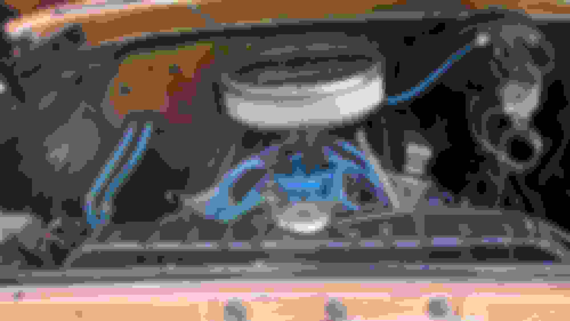
Your photo shows a wire behind the distributor. On a stock FE that should be the temp sensor in its correct location. Did someone add a second temp gauge?
Have other photos in my profile. Also, specific routing is not important as you're just creating a loop. Valve can be installed in either hose as well.
Maybe others can chime in as to which is correct as original, but I've seen both ways.
Economy fresh air heater has a manually operated heater water shut-off valve: C5TZ-18495-A / Obsolete ~ Available NOS
Deluxe fresh air heater has two cables mounted to a bracket under the dash to the right of the steering column.
C3UZ-18495-A .. Cable Operated Heater Water Valve (Motorcraft YG-133) / Available from Ford, repro parts sellers, auto parts stores.
Both of these valves are located on the fender apron, spliced into the inletto heater core heater hose, just behind the starter solenoid (relay).
Originally Posted by AZSCAWPION
Valve can be installed in either hose as well. Maybe others can chime in as to which is correct, but I've seen it both ways.
Quoted from my post #9, plus I've typed this same info a gazillion times in this forum, plus I owned a '65 F100 with the deluxe heater for 44 years, so I ain't just a whistlin' Dixie!
Quoted from my post #9, plus I've typed this same info a gazillion times in this forum, plus I owned a '65 F100 with the deluxe heater for 44 years, so I ain't just a whistlin' Dixie!
Thanks for the clarification ND. I guess my post should have read that I've seen both connections at the core used as the inlet side (as determined by which was connected to the water pump). I still don't know which is factory correct as I've seen it both ways.
I'd just switch the wires to start. Chances are the aftermarket gauge would work if connected to the original sensor.
You'd be surprised what people do over the course of 50+ years. When I got my truck the PO had connected the ignition switch to the very temp sensor I pointed out. Many other wires connected wrong in a domino affect. Hours of "fun" ensued.
I tried to switch the wire on the sensors. The stock sensor wire pops right off but the aftermarket sensor wire won't come loose. I'll work on this more later. I took some pics under the dash to see if I can figure out some of the wiring. I don't think I stand a chance.
The rat's nest will have to wait until I can pull the seat out. I can't get under there to work on it with the seat in.
Joe:
Both holes have the same thread, so you can use whichever temp sender you need and place a 90-degree elbow in the other one for your heater hose. Since the hoses were disconnected...I would almost expect your heater core to leak....watch for water under the dash. If you want to keep a second sender for the factory gauge, you can also get a thermostat housing (water neck) with female threads for an additional sender.
Thanks. I don't know if the hoses were disconnected because of a problem with the heater core, or to allow them to hook up the aftermarket temp sensor. I guess I should check the integrity of the core before going any further. The heater blower doesn't work, but I don't even know if it's getting power yet. The wiper motor doesn't work, but again, I don't know what all the PO did to the wiring.
Not familiar with an aftermarket wiring kit, don't have a clue where those wires are running. Should be a single wire running from the water sending unit directly to the gauge and a single wire running from the gauge to the 'constant voltage regulator' in series with the other gauges. Not sure Ford truck wiring manual 65-66 would be of any help; posting link to thread member posted may, or may not find helpful.
Joe I think the reason why you can't get the wire off of the after market sensor is because it's a probe and it is one piece connected to the gauge. Like the one in the following picture. , Doug.
Joe I think the reason why you can't get the wire off of the after market sensor is because it's a probe and it is one piece connected to the gauge. Like the one in the following picture. , Doug.
You are exactly right. I thought it might be something like that. Thanks for the pic Doug.
Not familiar with an aftermarket wiring kit, don't have a clue where those wires are running. Should be a single wire running from the water sending unit directly to the gauge and a single wire running from the gauge to the 'constant voltage regulator' in series with the other gauges. Not sure Ford truck wiring manual 65-66 would be of any help; posting link to thread member posted may, or may not find helpful.
Thanks Dave. I printed out those diagrams and I'll use them along with the laminated one I got from ClassicCarWiring.com. The fuse panel shown on that one has only 3 fuses, and the one in my truck has 5 fuses, so I'm already confused.
EDIT:
I still haven't found enough information to troubleshoot the wiring in my truck. I have now ordered the reprinted Ford wiring diagrams (12 pages) from Faxon Auto Literature. It's ironic that I moved to VA 3 months ago from Riverside, CA, which is where Faxon is located. I ordered the 1965 Ford F-100 thru F-750 Truck Wiring Diagram Manual Reprint. Hopefully that will give me enough information to figure out how the truck was hacked.
Never installed the valve, if it would provide additional heat to the cab I probably should?; having said that, routed the hose closest to the inner fender to the water pump, the outer hose to the intake manifold. Believe the valve is inline with the hose that connects to the manifold.
Not to rob a thread but...what booster and master cyl combo is that you have there? Is that original on a 65? Looks like a 78/79 era? Thanks
If I recall, many " years ago salvaged the 'booster' off a 76-77 truck, along with the bracket and master cylinder. Later purchased a master cylinder replacement thru NAPA auto parts. Kept the pressure brake switch using a T fitting, prudent to convert to switch.
If I recall, many " years ago salvaged the 'booster' off a 76-77 truck, along with the bracket and master cylinder. Later purchased a master cylinder replacement thru NAPA auto parts. Kept the pressure brake switch using a T fitting, prudent to convert to switch.
 02-26-2017, 11:29 AM


 as well. Maybe others can chime in as to which is correct, but I've seen it both ways.


 , Doug.