F1 headers, motormounts and crossmembers Oh MY!


#17
 08-31-2015, 05:06 PM
#18
08-31-2015, 05:19 PM
Shoo, yes anything can be done more than one way, Never did I say this was the only way that a crossmember should be built. But I think this design satisfied all the parameters we set for it, others may have different parameters and goals. My intentions is to show what we are doing on Gary's build, solving problems and our thought process as we go along since there is very little aftermarket support or information available and Ford made/makes each of it's engines so unique that it's very likely there never will be much aftermarket support (there must be a half doz or more variants on just the 4.6L version of the mod motor that share almost no interchangeable parts or electronics). So many here keep chanting the Ford in a Ford mantra, but Ford stopped making carburated pushrod engines decades ago, rebuildable cores are getting nearly as scarce as flatheads and if you handed a carb to a lot of younger gearheads, they'd ask what it is, or where do you hook up the laptop to adjust it. If it were mine I'd have done like droptop and put a GM LS engine and tranny that has interchangability and therefore a lot of aftermarket support, in it and been done already. We are having to break all new ground, and our solutions work so far. You (the universal you not the personal you) probably won't like our engine mount solution either because it too is a unique outside the box solution.
Mike, The only thing that upset me is people being critical of the design before I even showed the finished piece or had a chance to explain the thinking that went into it (Believe me a LOT of thinking and redesign went into it).
C91x, yes it probably is somewhat over designed, but since it wasn't my truck it was going on, I erred on the conservative side and also wanted to make it as versatile as possible. there will be almost no force exerted by the engine on it, the laminated mount is so soft it's almost being supported by a pillow. I designed it to be bolted in to start with since we are doing so much inventing as we go along there is some chance it may need to be moved or replaced in the future. If not then later the ends could be welded in if Gary decided to do so, since the center could still be unbolted for trans removal. Even if left bolted in it is likely that wires and brake, fuel lines may be run along the inside of the frame thru the triangular spaces making removal of the end sections difficult. Then again personally I'm not fond of welding on my back upside down when I can weld sitting down at the bench.
#19
08-31-2015, 08:18 PM


#20
08-31-2015, 09:43 PM

#23
09-01-2015, 09:51 AM
Elder User
Join Date: Jun 2013
Location: Metro Detroit-MI
Posts: 949
Likes: 0
Received 0 Likes
on
0 Posts
#24
09-01-2015, 02:19 PM
#25
09-01-2015, 03:13 PM
Why did you file down the crush tubes to 1/16" wall? If you are using 3/8" bolts a piece of 5/8" OD with 1/8" wall would have been what to use. Most like to use a crush tube of the same thickness as the piece it will be shoring up instead of working harder to thin it out. Odd choice.
1. It was the size tubing I had on hand, and would have plenty of strength for crush tube for this application. 1/2" was also the largest size twist drill I had on hand, had I had a 33/64" drill I could have saved a lot of time and effort.
2. Tubing has tremendous crush strength in the longitudinal direction. A 1" length of plastic soda straw would support your weight if it didn't bend. (proof experiment 1: Take an undamaged standard soda straw, even a paper one will work. Close off one end with your finger. Now bring the open end down rapidly onto a raw potato held between the fingers of the other hand. You can easily drive the straw completely through the potato without damaging the straw, the column of air trapped inside kept the straw from bending. ASIDE PS-Announcement: You or especially your kids should never drink thru a straw in a car unless it is a bendy one, a crash or even sudden stop could easily drive the straw thru your/their brain! You're welcome...)
Proof 2: thread a 1" length of the steel 1/16" wall tubing onto a 3/8" bolt with washers and nut, get out your longest wrenches and try tightening the bolts until the tubing crushes. It's a pretty good bet that the bolt or wrench breaks before you can crush it very far. As you compress the tubing you are increasing it's strength many fold, the more you compress it the more it will resist crushing, and that doesn't even consider the square tubing's additional crush strength it's welded to. (HS physics, but I also took physics in college.)
3. All they are there for is to assure the bolts don't work loose/rat out the holes. If I had been building it for my own use I wouldn't have bothered, just used matching grade 1"OD washers. (They were also used here as a teaching lesson for Gary, but shhh don't tell him).
#26
09-01-2015, 03:38 PM
Cargo Master
Crossmember looks good, as stated there is more than one way to do it. I used a mid 70s camaro crossmember, just had to cut the tab off, set the angle, and weld. Quick and dirty. I have a piece of tube steel across the top of my rails to tie the upper halves together so nothing needed on the crossmember.

#27
09-01-2015, 04:30 PM
Please note there are a number of technical, drawing and detail errors in the motor mount drawing above and changes were made up to and during fabbing the final assemblies.
Materials used for the motor mounts:
3.5" OD 1/8" wall DOM tubing
1/8" plate steel
Set of Speedway motors #7209314 universal bolt through engine mount cushions
(2) 5/8" NF grade 8 bolts x 4.5" with washers and nylok nuts.
Assorted bolts and nuts
Materials used for the motor mounts:
3.5" OD 1/8" wall DOM tubing
1/8" plate steel
Set of Speedway motors #7209314 universal bolt through engine mount cushions
(2) 5/8" NF grade 8 bolts x 4.5" with washers and nylok nuts.
Assorted bolts and nuts
#28
09-01-2015, 04:40 PM
Crossmember looks good, as stated there is more than one way to do it. I used a mid 70s camaro crossmember, just had to cut the tab off, set the angle, and weld. Quick and dirty. I have a piece of tube steel across the top of my rails to tie the upper halves together so nothing needed on the crossmember.

#29
09-03-2015, 01:55 PM
AXracer,
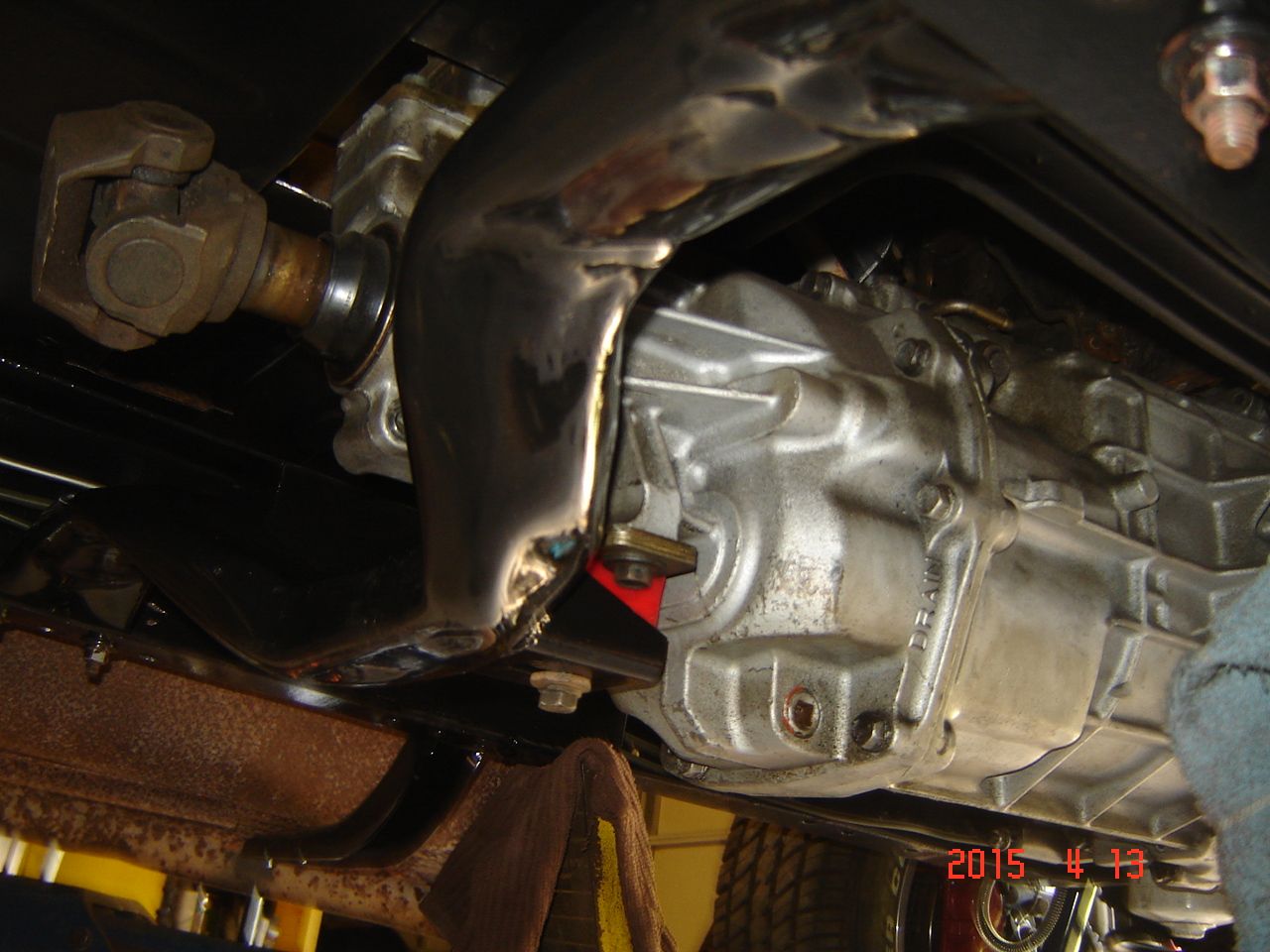
An excellent, well thought-out design. The only question I had I was able to answer myself. How do you remove the transmission? I see that by removing the bolts holding the bolt-on gusset plates on either side and the bolts holding the center section, the center piece will slide right out. Great plan.
Phil
#30
09-03-2015, 02:00 PM
Phil