When you click on links to various merchants on this site and make a purchase, this can result in this site earning a commission. Affiliate programs and affiliations include, but are not limited to, the eBay Partner Network.
Have you considered grafting a frame section from another truck onto your frame? Rather than dumping a hot of heat and time into it, just chop, measure and weld in the new section that you need
I did consider that and, in fact, have the two front frame horns from a '77 F-250 sitting in my shop. Unfortunately, that's a much heavier frame. I could make it work (sectioning) but that would be a lot of work too. I am on the lookout for an F-100 or F-150 frame that I can cut the horns off of but no luck so far.
Yet another fallback option is to fabricate that frame horn. The key to making that work would be getting the radiator crossmember holes and the bumper bolt in the right place.
Still, I've made some progress on the driver's side and will post a few pictures later today or tomorrow.
I recently saw a stripped half ton frame on my local CL for a few hundred. I will see if I can track down the link again. Maybe the seller would be willing to lop off the section you need and mail it to you.
I recently saw a stripped half ton frame on my local CL for a few hundred. I will see if I can track down the link again. Maybe the seller would be willing to lop off the section you need and mail it to you.
Thanks, that would be a good fallback option to have.
The driver side frame horn is proving to be a formidable challenge. Here are a few pictures that help make that point. First up is a comparison of the driver side frame rail on an undamaged F-100 and the same area on the wrecked F-150. The view of the F-100 on the left is what both vehicles should look like. Contrast that to the image on the right which shows the badly mangled driver side frame horn on the wrecked F-150.
The next image shows the slightly improved state of the driver side frame horn. It's still pretty ugly but a little less ugly than before.
The next two images show how the selective application of heat coupled with force applied in a specific direction can reverse some of the damage done in a collision.
Other contraptions exert force in different ways.
This part of the frame horn is starting to open up.
It may also be necessary to improvise various ways to exert force where you think it is needed.
So this is where I am at present. There's still lots more fun to be had with this.
BTW, if you saw the 1983 film adaptation of Steven King's "Christine" you'll remember the "show me" scene where this wrecked 58 Plymouth Fury reforms itself. I tried saying "show me" to this truck. It didn't work.
HIO Silver suggested that a wheelbase measurement was in order so that "tweaking" in the more important areas of the frame could be ruled out. I had already done that but the suggestion caused me to think a bit more deeply about this critical data point. If both sides aren't equal, something is amiss. One might be a "sidewinder" and not be aware of it.
Thus, accuracy in measurement becomes very important. Here's how I went about this task. Maybe there is a better way.
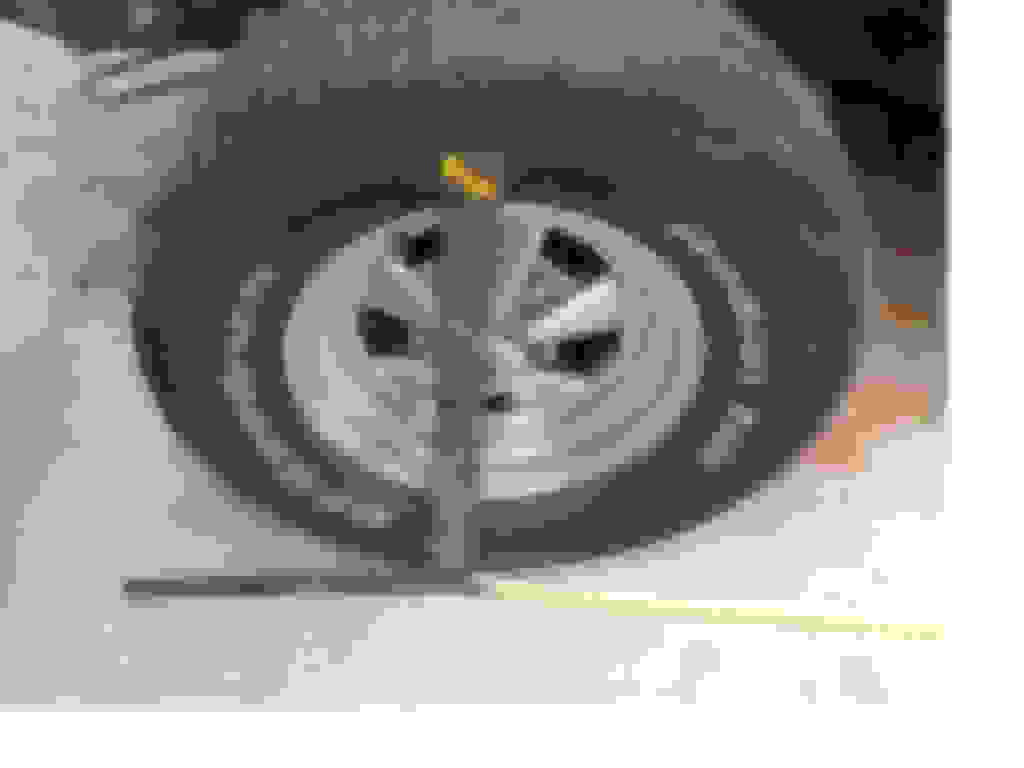
The first thing I did was to get the wheels close to straight forward as I could. Then I used a metal square to locate a point on the ground equal to the wheel center. Here is the driver side:
front - driver side
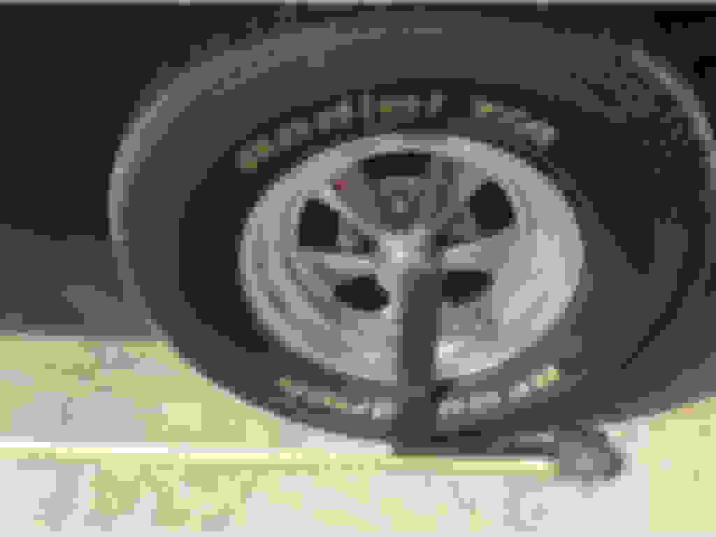
... and here is the passenger side
rear - driver side
Driver side w/ tape
Passenger side w/ tape
Here is the driver side wheelbase:
Driver side wheelbase
Here is the passenger side wheelbase:
Passenger side wheelbase
So the wheelbase measurements on both sides are equal. This is good news but there are more measures that can be taken.
personally id take a measurement from the rear axle tube to center of the kingpin much more accurate than hoping you have the wheels straight then do an X Measurement from the same points
It is okay to ask then do it your way. Sometimes that's how you learn there is a question you did not know existed, because something was mentioned and see it in another light.
Several ways to fix it actually, he seems to have taken the most difficult method I can think of. I'd of straightened the right side as he did, then cut the left off and replaced it with a straight piece, boxed them for support if all else checked out.
But that takes welding and some don't have the equipment or ability and that's okay too
After seeing a pic of the whole truck i see why you are trying to repair rather then part it out. As for the repair i woukd have done exactly as you did on the pass. side rail but i would have cut off the drivers one and replaced it. There is no saving that one, its way too deformed/stretched to ever get it back. Its a day job to cut off the bent horn and weld on a new one and it would be a better repair. Kudos for trying to save that truck, most folks wouldnt
personally id take a measurement from the rear axle tube to center of the kingpin much more accurate than hoping you have the wheels straight then do an X Measurement from the same points
This is a newer listing that I found while looking. Its a 4x4 frame, so im not sure if the horns are the same.
The 4X4 frame definitely won't work due to the differences in front suspension (leaf sprigs vs dual I-beams and coils).
The 78-79 might work but I see many differences between my frame and this one (coil towers, engine x-member) so I'd want to get a tracing first. I'll contact the seller. If I were the seller, I'd be open to selling that piece for the price of the whole frame but not less.
Oops, I just read that the seller says phone only. Because of my hearing impairment, I don't do we'll over the phone. F2F, I can read lips and use other contextual cues but voice only phones don't work for me.
I'd of straightened the right side as he did, then cut the left off and replaced it with a straight piece, boxed them for support if all else checked out.
No doubt that this is the road less travelled (like the Robert Frost poem of the same name). On the driver side, I'd be happy to find a decent frame horn and weld it in. I have gas, arc and MIG welding. I'm pretty good with gas, OK with arc and just learning MIG. I thought that I had that option with the F-250 frame horns but, despite the fact that they have the right shape, they are made of heavier gauge steel and are taller (top to bottom rail).
As you mentioned, there are ways to compensate for all that heat, stretching and banging such as boxing parts of the frame. There is also annealing (stress relief), tempering via quenching and adding a crossmember.
I was very lucky on the passenger side. Here's why. The passenger side is where the VIN is stamped in two places (top rail just below where the alternator is usually located and further back just under the passenger's butt). I'm located in Georgia which did not start using car titles until 1985 so it's quite common here to sell a pre-'85 vehicle with nothing more than a Bill of Sale and a recent registration slip. With that and proof of insurance, one can get a tag and live happily ever after.
The registration VIN matched the VIN on the warranty plate riveted to the driver side door. The door jamb sticker was illegible even after wet sanding the paint covering it. There is no VIN plate on the dash as with later models. However, there was a problem with this truck. Unbeknownst (maybe) to the PO, the door had been changed and, with it, the warranty plate. The VIN on the frame was different.
Since this truck was originally purchased for parts, that wasn't a problem but once I decided to repair it, that issue became very important.
Consulting with the local tag office, I learned that I could obtain a form that would be filled out by a sheriff's deputy after eyeballing the VIN. That's been done and it wasn't difficult for the neatly uniformed sheriff's deputy because I had removed the entire front clip. How they would handle this task with a fully dressed vehicle is hard to imagine. BTW. there is a company that will produce new warranty door plates with the correct VIN. So, eventually, all will be Kosher.
This is why I went after the passenger side first. If that couldn't be saved, the legitimacy of the vehicle would always be in doubt and jeapordize any return on the investment.
So, that's my VIN-tage truck story and I'm sticking to it.
Not a whole lot of progress to report as rain and an upper respiratory infection have slowed me down.
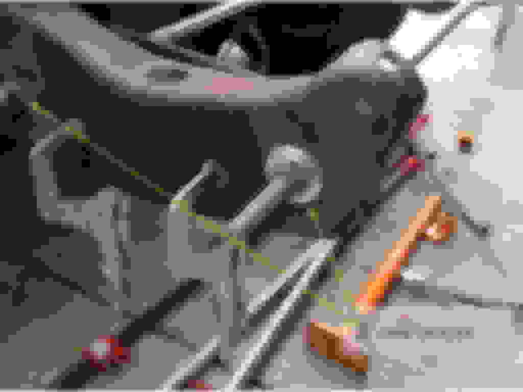
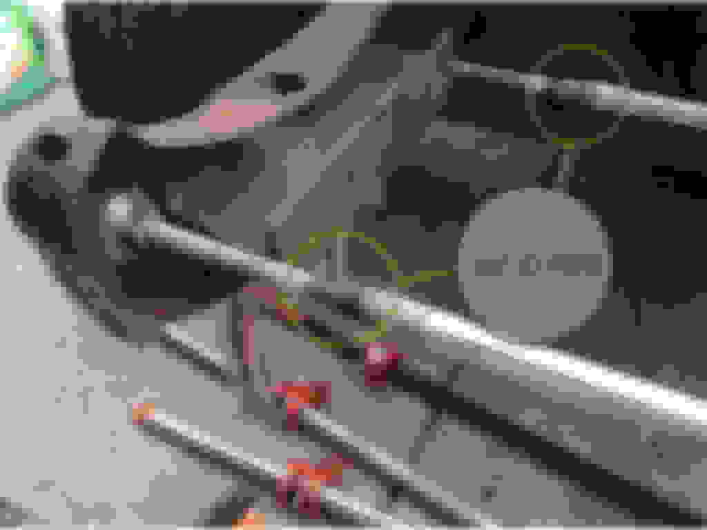
I wasn't happy with the behavior of those pipe clamps. They only work in one direction at a time. Time to fabricate a better solution. Sacrificing one of those .50" ID pipe clamps, loping off the heads of some long .50" OD bolts and a little welding produced a much firmer solution.
Bolts and washers on both sides provides two-way resistance to movement as contrasted with the unidirectional resistance of the pipe clamp.
With this newfound firmness, it became possible to push sections of the driver side frame horn from the passenger side frame horn. Using a small I-beam against cold steel spreads and thus diminishes the psi force applied to the passenger side. Using heat and a smaller force footprint on the driver side encourages movement.
So far, I've made two of these and will probably make at least two more. I've used existing holes in the fame thus far but I'm not above drilling some new ones if that seems necessary.
I did a little pushing and pulling after developing the new frame constraints and think I see some improvement.
Even tho' the wheelbase is the same 133" on either side the left side could be "back" farther than the right side.If the whole entire left side moved backwards say,1 whole foot,the wheelbases would still remain the same.That is the "diamond" that has been mentioned.To check this you need couple of reference points ,underneath, on the frame (because the top of the frame is covered w/body and box) probably around the rear tranny maybe cab area. Pick 2 holes on either side,or 2 bolts that look like they are located the same on either side or 2 pins,side,bottom,makes no difference as long as they are in the same spot on either left or right frame. Now... measure from one of those predetermined reference points to another point back on the frame or directly under the axle AT A 45% ANGLE.In other words, 1 end of the tape at the rt.starting point and the other end ACROSS the truck to the opposite lft.side. Then measure the left starting point to the rear right side.They need to match or you have a diamonded frame.You will find MANY of these points under a frame and you will be fine as long as you use dead- on corresponding points fore and aft. Now, with all that said,the #2 most critical possible problem that you need to address is the UP and DOWN of the frame. A pretty good hit like that generally does not just generate a straight back energy.It goes where it wants to.So... two good ,hopefully level places to support the frame off a level floor in the rear.Measure from the floor up where supported;they have to be dead on so your next measurements are proper,then support the front on either side where you think it is possibly undamaged.Now front and back ,where supported don't have to match.Just the support area left and right in the rear and then left and right area in the front. Go down EACH side of the frame in spots that are the same and compare measurements.This will give the up & down differences.Hopefully you have none.#3 most critical if you can make it by all this stuff IS the radiator support etc. But that is all adjustable,shimmable,etc,if you are pretty darn close. This is a quicky frame rundown,I hope it is understandable. Oh,one other thing,on those kinks that don't want to iron out up front,take a cut off wheel and just "slice" the kink.After straightening weld the slice back up.You'll be fine! Good luck,Gary
Even tho' the wheelbase is the same 133" on either side the left side could be "back" farther than the right side.
Thanks Gary, good advice throughout.
I'm working on the concrete apron right outside my shop. It has a slight incline for drainage so I'll need to make sure that the jack stands are equidistant from the surface. Once that's done, I plan to do several kinds of measurements as follows:
1) using a plumb at the kingpin centers and similar points at the rear axle, I can get a more accurate reading of the wheelbase. More importantly, I can measure from the driver side king pin to the rear axle center on the passenger side and compare that to the distance between the passenger side kingpin and the driver side axle center. If the driveline is running "square" or "squarely" those two numbers should be essentially equal. I'll need to be very careful on the rear axle to take measurements that are the same distance from the brake backing plates on both sides.
2) Since the frame should be perpendicular to the surface, though at a slight angle, I can then check for equality on the vertical plane at several points on both sides of the frame as well.
Since I have an undamaged F-100 of the same year ('76) that I am using for reference, I will post the dimensions I find there that I did not find in the Ford documentation such as the distance between the center of the radiator crossmember holes as well as the distance between the frame alignment pins closest to them. There are two more frame alignment pins at the centerline of the front axles. I'm not sure that I can reach and measure them in any useful way but I will try. These four data points would be very useful.

 08-30-2014, 10:24 AM