Dana 50 spindle nut. No idea.

#17
 12-04-2013, 07:45 AM

Join Date: Sep 2003
Location: TX
Posts: 2,731
Likes: 0
Received 0 Likes
on
0 Posts
Yes I have autozone, oreilleys, napa, etc. No one has what I need or I would just buy some, and take back the ones that didn't fit. I do not have the time or money to order the wrong sized socket, pay to have it shipped, and wait for a new one to ship back out. My truck is currently up on a jackstand.
So to clarify, and simplify.
What sized rounded hex do I need to buy in order to removed the spindle nut off of my 1997 F250 Dana 50 IFS with auto hubs?
#18
12-04-2013, 08:09 AM
Post Fiend
I'm just thinking out loud here, but could you swing it to order all three sizes and then return the two you don't need? I'm sure they're not cheap, but that's the only way I know of that you could be sure to get the one you need for sure without having to wait for the shipping three times over.
Either that, or if you can somehow get it off the truck and measure it, you could then order just the one you need to have for reassembly.
Either that, or if you can somehow get it off the truck and measure it, you could then order just the one you need to have for reassembly.
#19
12-04-2013, 08:12 AM
#20
12-04-2013, 08:20 AM
Join Date: Sep 2003
Location: TX
Posts: 2,731
Likes: 0
Received 0 Likes
on
0 Posts
I'm just thinking out loud here, but could you swing it to order all three sizes and then return the two you don't need? I'm sure they're not cheap, but that's the only way I know of that you could be sure to get the one you need for sure without having to wait for the shipping three times over.
Either that, or if you can somehow get it off the truck and measure it, you could then order just the one you need to have for reassembly.
Either that, or if you can somehow get it off the truck and measure it, you could then order just the one you need to have for reassembly.
#21
12-04-2013, 08:20 AM
Join Date: Sep 2003
Location: TX
Posts: 2,731
Likes: 0
Received 0 Likes
on
0 Posts
#22
12-04-2013, 09:06 AM
Performance Tool part # w83246. 2-3/4"
Got mine at oreillys
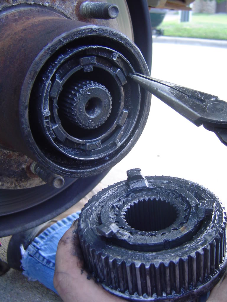
As far as the spindle nut there is a lip on it and the internal threads have grooves through them as well but it doesn't look like in your pic there is anything else holding it on. You obviously made it this far but I'll put up these pics anyway for you to compare to and see if something was missed.
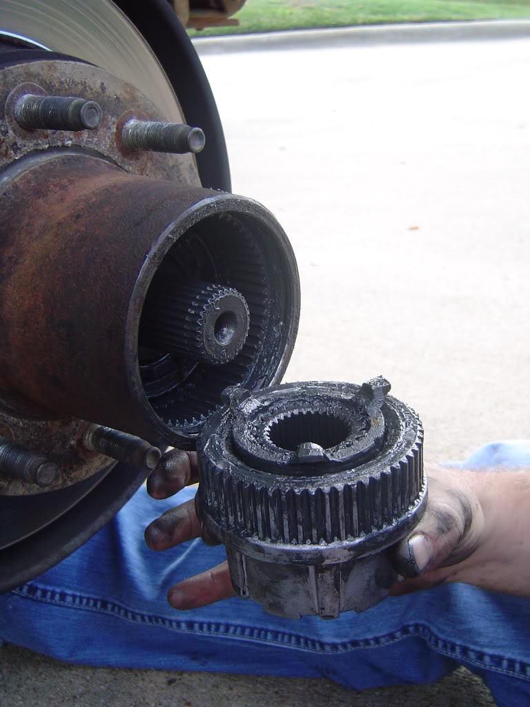
Hub
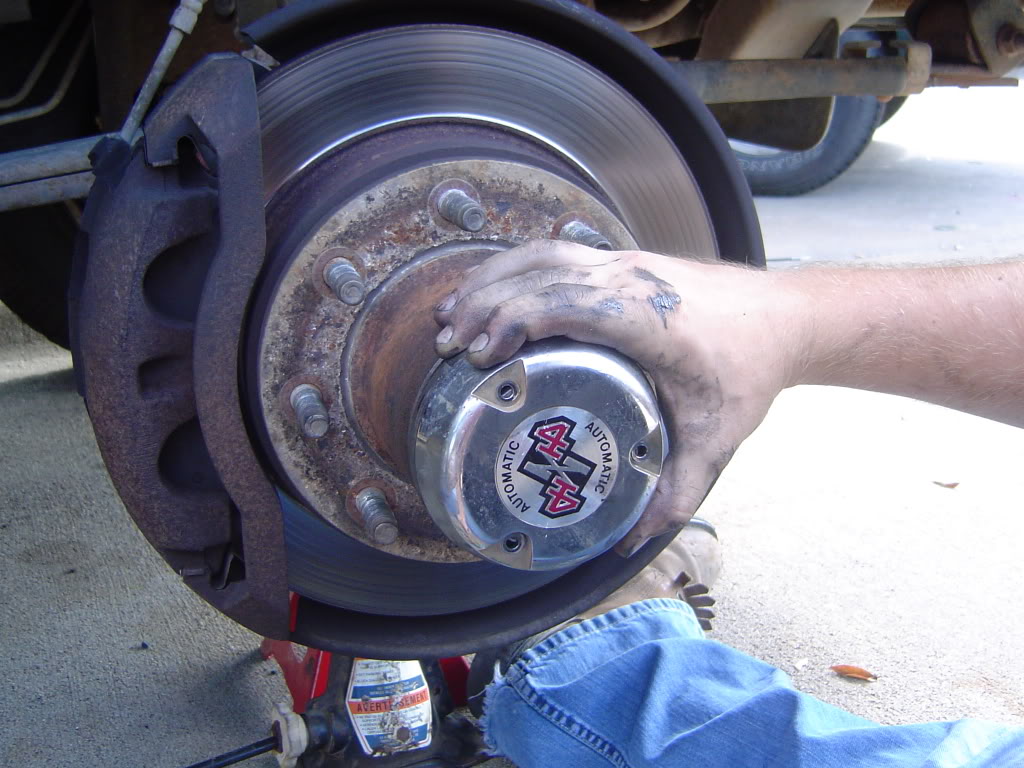
Cover Off
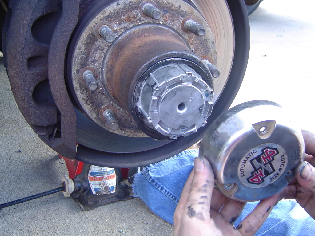
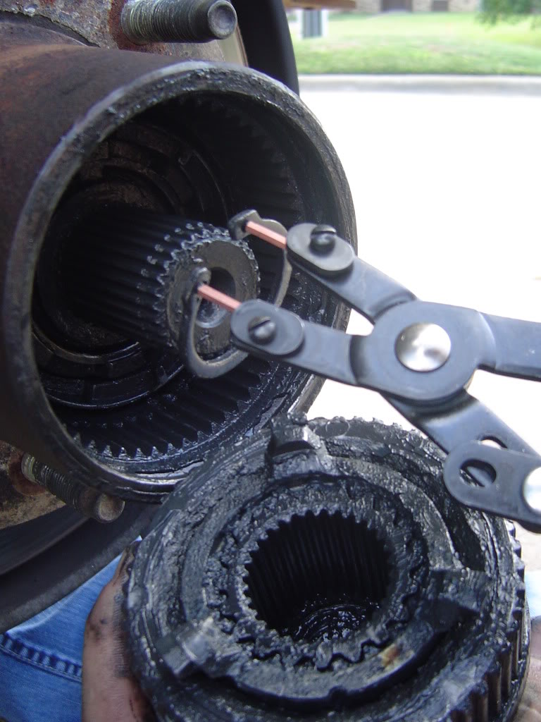
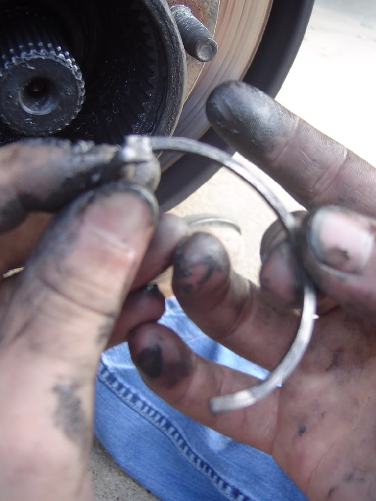
Remove snap ring from inside hub groove
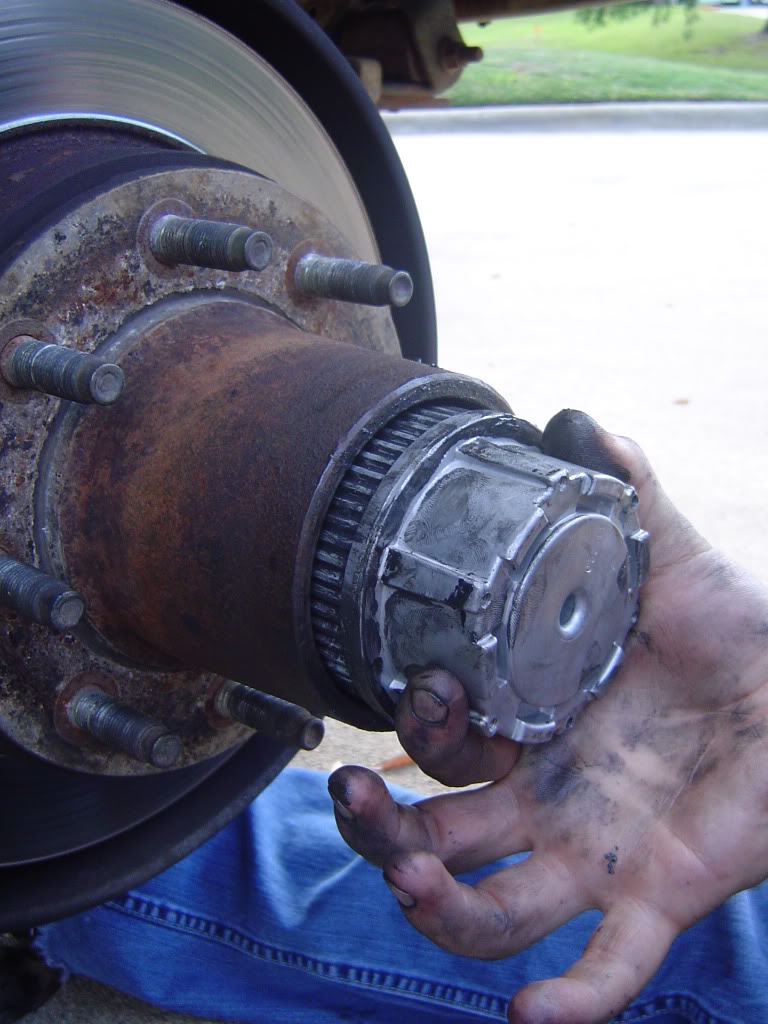
Pull the auto hub assembly out
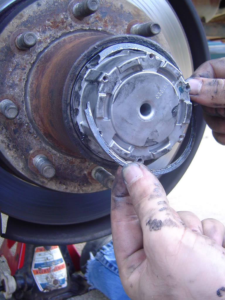
Looks like this
Snap ring off of groove on axle stub
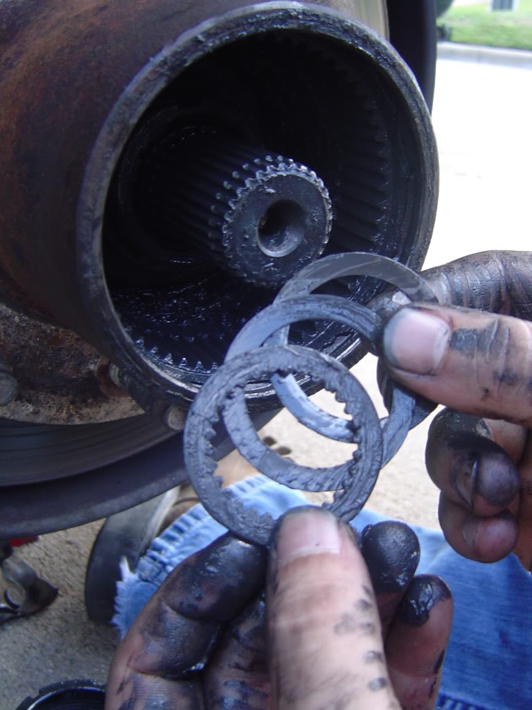
Washer stack out from behind snap ring
Note: There should be three washers. They come out splined, plastic, and metal and go back in metal, plastic, splined.
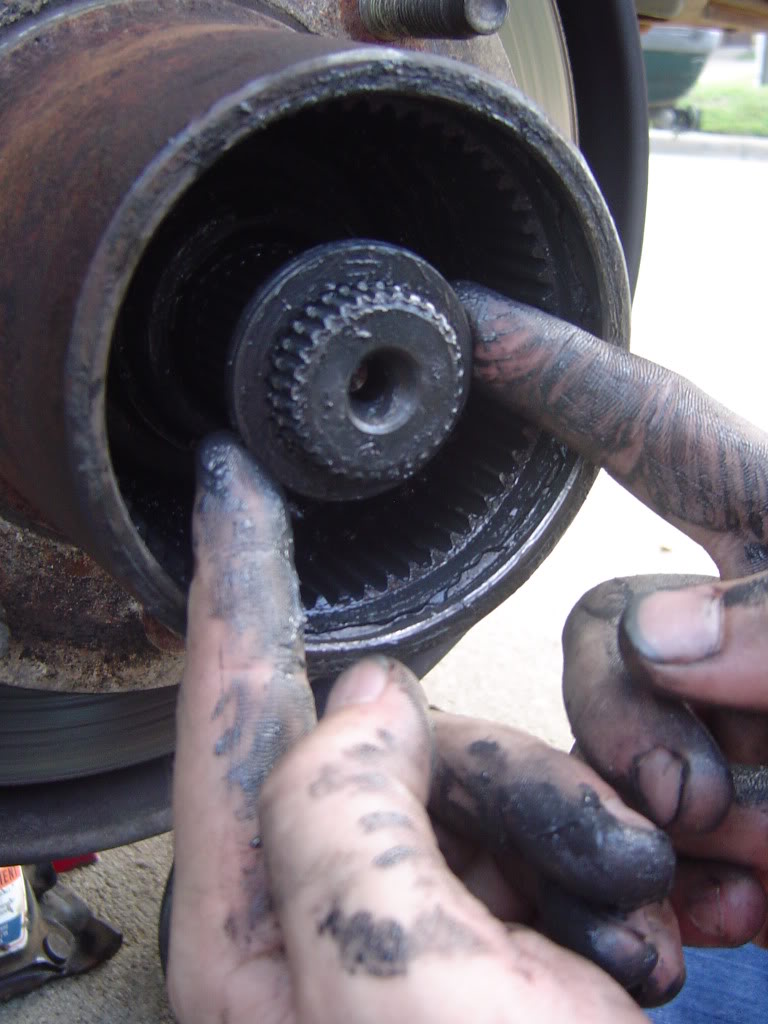
Pull the cam out
C clip comes out next
After that is the spindle nut, bearings, and oil seal. I don't have any more pictures from there. Hope some of this helps.
Got mine at oreillys
As far as the spindle nut there is a lip on it and the internal threads have grooves through them as well but it doesn't look like in your pic there is anything else holding it on. You obviously made it this far but I'll put up these pics anyway for you to compare to and see if something was missed.
Hub

Cover Off

Remove snap ring from inside hub groove

Pull the auto hub assembly out

Looks like this

Snap ring off of groove on axle stub

Washer stack out from behind snap ring

Note: There should be three washers. They come out splined, plastic, and metal and go back in metal, plastic, splined.

Pull the cam out

C clip comes out next

After that is the spindle nut, bearings, and oil seal. I don't have any more pictures from there. Hope some of this helps.
#23
12-04-2013, 10:11 AM
Last one. From the shop manual:
Automatic Locking Hub, F-250, F-350

<table width="70%" border="1" cellspacing="0" cellpadding="3"><tbody><tr><th valign="bottom">Item</th><th valign="bottom">Part Number</th><th valign="bottom">Description</th><tr valign="top"><td>1</td><td>3A329</td><td>Halfshaft</td></tr><tr valign="top"><td>2</td><td>3C132</td><td>Rolling Diaphragm Seal (RDS), Axle</td></tr><tr valign="top"><td>3</td><td>3299</td><td>Integral Spacer Needle Bearing Seal</td></tr><tr valign="top"><td>4</td><td>3123</td><td>Bearing, Caged Needle</td></tr><tr valign="top"><td>5</td><td>3105</td><td>Front Wheel Spindle</td></tr><tr valign="top"><td>6</td><td>1190</td><td>Wheel Hub Grease Seal</td></tr><tr valign="top"><td>7</td><td>4221</td><td>Inner Wheel Bearing (with Bearing Cup � 4222)</td></tr><tr valign="top"><td>8</td><td>1102</td><td>Front Disc Brake Hub and Rotor</td></tr><tr valign="top"><td>9</td><td>4221</td><td>Outer Wheel Bearing (Bearing Cup � 4222)</td></tr><tr valign="top"><td>10</td><td>3B549</td><td>Wheel Retainer Key</td></tr><tr valign="top"><td>11</td><td>�</td><td>Steel Thrust Washer (Part of 3B458)</td></tr><tr valign="top"><td>12</td><td>�</td><td>Splined Thrust Washer (Part of 3B458)</td></tr><tr valign="top"><td>13</td><td>�</td><td>Lock Ring (Part of 1K106)</td></tr><tr valign="top"><td>14</td><td>1K104</td><td>Capscrew</td></tr><tr valign="top"><td>15</td><td>1K104</td><td>Cap</td></tr><tr valign="top"><td>16</td><td>1K105</td><td>Hub Body</td></tr><tr valign="top"><td>17</td><td>3B457</td><td>Snap Ring</td></tr><tr valign="top"><td>18</td><td>�</td><td>Plastic Thrust Washer (Part of 3B458)</td></tr><tr valign="top"><td>19</td><td>�</td><td>Cam Assembly (Part of 1K105)</td></tr><tr valign="top"><td>20</td><td>�</td><td>Wheel Retainer (Nut) (Part of 1K105)</td></tr><tr valign="top"><td>A</td><td>�</td><td>Tighten to 4-6 Nm (35-53 Lb-In)</td></tr><tr valign="top"><td>B</td><td>�</td><td>While Rotating Front Disc Brake Hub and Rotor, Tighten to 68 Nm (50 Lb-Ft) to Seat Wheel Bearings. Back Nut Off 90 Degrees (1/4 Turn). Tighten to 1.8 Nm (16 Lb-In)</td></tr></tbody></table>
Removal
 CAUTION: Do not drop hub components during removal and installation.
Automatic Locking Hub, F-250, F-350
<table width="70%" border="1" cellspacing="0" cellpadding="3"><tbody><tr><th valign="bottom">Item</th><th valign="bottom">Part Number</th><th valign="bottom">Description</th><tr valign="top"><td>1</td><td>3A329</td><td>Halfshaft</td></tr><tr valign="top"><td>2</td><td>3C132</td><td>Rolling Diaphragm Seal (RDS), Axle</td></tr><tr valign="top"><td>3</td><td>3299</td><td>Integral Spacer Needle Bearing Seal</td></tr><tr valign="top"><td>4</td><td>3123</td><td>Bearing, Caged Needle</td></tr><tr valign="top"><td>5</td><td>3105</td><td>Front Wheel Spindle</td></tr><tr valign="top"><td>6</td><td>1190</td><td>Wheel Hub Grease Seal</td></tr><tr valign="top"><td>7</td><td>4221</td><td>Inner Wheel Bearing (with Bearing Cup � 4222)</td></tr><tr valign="top"><td>8</td><td>1102</td><td>Front Disc Brake Hub and Rotor</td></tr><tr valign="top"><td>9</td><td>4221</td><td>Outer Wheel Bearing (Bearing Cup � 4222)</td></tr><tr valign="top"><td>10</td><td>3B549</td><td>Wheel Retainer Key</td></tr><tr valign="top"><td>11</td><td>�</td><td>Steel Thrust Washer (Part of 3B458)</td></tr><tr valign="top"><td>12</td><td>�</td><td>Splined Thrust Washer (Part of 3B458)</td></tr><tr valign="top"><td>13</td><td>�</td><td>Lock Ring (Part of 1K106)</td></tr><tr valign="top"><td>14</td><td>1K104</td><td>Capscrew</td></tr><tr valign="top"><td>15</td><td>1K104</td><td>Cap</td></tr><tr valign="top"><td>16</td><td>1K105</td><td>Hub Body</td></tr><tr valign="top"><td>17</td><td>3B457</td><td>Snap Ring</td></tr><tr valign="top"><td>18</td><td>�</td><td>Plastic Thrust Washer (Part of 3B458)</td></tr><tr valign="top"><td>19</td><td>�</td><td>Cam Assembly (Part of 1K105)</td></tr><tr valign="top"><td>20</td><td>�</td><td>Wheel Retainer (Nut) (Part of 1K105)</td></tr><tr valign="top"><td>A</td><td>�</td><td>Tighten to 4-6 Nm (35-53 Lb-In)</td></tr><tr valign="top"><td>B</td><td>�</td><td>While Rotating Front Disc Brake Hub and Rotor, Tighten to 68 Nm (50 Lb-Ft) to Seat Wheel Bearings. Back Nut Off 90 Degrees (1/4 Turn). Tighten to 1.8 Nm (16 Lb-In)</td></tr></tbody></table>
Removal
CAUTION: Do not drop hub components during removal and installation.- Separate cap from body assembly by removing the three capscrews, using Torx� bit TX25 or equivalent, from the cap.
- Remove cap.
- Remove the lock ring seated in the groove of the front disc brake hub and rotor (1102).
- Remove the body assembly from the front disc brake hub and rotor.
Automatic Locking Hub, Disassembled View, Typical

<table width="70%" border="1" cellspacing="0" cellpadding="3"><tbody><tr><th valign="bottom">Item</th><th valign="bottom">Part Number</th><th valign="bottom">Description</th><tr valign="top"><td>1</td><td>1K104</td><td>Cap</td></tr><tr valign="top"><td>2</td><td>1K105</td><td>Hub Body</td></tr><tr valign="top"><td>3</td><td>3B457</td><td>Snap Ring</td></tr><tr valign="top"><td>4</td><td>�</td><td>Plastic Thrust Washer (Part of 3B458)</td></tr><tr valign="top"><td>5</td><td>�</td><td>Cam Assembly (Part of 1K105)</td></tr><tr valign="top"><td>6</td><td>�</td><td>Wheel Retainer (Nut) (Part of 1K105)</td></tr><tr valign="top"><td>7</td><td>3B549</td><td>Wheel Retainer Key</td></tr><tr valign="top"><td>8</td><td>�</td><td>Steel Thrust Washer (Part of 3B458)</td></tr><tr valign="top"><td>9</td><td>�</td><td>Splined Thrust Washer (Part of 3B458)</td></tr><tr valign="top"><td>10</td><td>�</td><td>Lock Ring (Part of 1K106)</td></tr><tr valign="top"><td>11</td><td>1K104</td><td>Capscrews (3)</td></tr><tr valign="top"><td>A</td><td>�</td><td>While Rotating Front Disc Brake Hub and Rotor, Tighten Wheel Retainer (Nut) to 68 Nm (50 Lb-Ft) to Seat Wheel Bearings. Back Nut Off 90 Degrees (1/4 Turn). Tighten to 1.8 Nm (16 Lb-In).</td></tr><tr valign="top"><td>B</td><td>�</td><td>Tighten to 4-6 Nm (35-53 Lb-In)</td></tr></tbody></table>
- Remove C-washer or snap ring from stub shaft groove.
- Remove spacers (three thrust washers) from shaft.
- Remove cam assembly. Pull to remove.
- If front disc brake hub and rotor and front wheel spindle (3105) are to be removed, refer to Wheel Grease Seal and Bearing, Front Replacement and Repacking in the Disassembly and Assembly portion of this section.
- Align the fixed cam retaining key on the cam assembly (garter spring inboard) with the keyway on the spindle. Firmly press the cam assembly on the wheel retainer nut.
- CAUTION: Improper sequence of three-piece thrust washers will result in excessive wear of assembly.
Install three-piece thrust washer set (first metal, second plastic, third splined) and retainer lock ring on C-clip. It may be necessary to push the axle outboard from backside of knuckle. Be sure retaining ring is seated in groove properly.
- CAUTION: Rotate moving cam stop (use any one of three) to the one o'clock position in relationship to the fixed cam retaining key.
CAUTION: Do not force body assembly into front disc brake hub on rotor if body assembly will not fit. Recheck alignment of all components.
NOTE: The hubs should not be packed with grease. Too much grease will damage the hubs and prevent proper operation.
Install body assembly into vehicle front disc brake hub and rotor by lining up the three legs outside the hublock body with the three pockets in the cam assembly.
- Make sure body assembly is in far enough to see groove in rotor tube. Install large lock ring into groove of hub. Be sure lock ring is correctly seated.
- Install cap to body assembly. Install three capscrews and tighten to 4-6 Nm (35-53 lb-in).
#24
12-04-2013, 10:32 AM
#26
12-04-2013, 11:11 AM
Postmaster
I bought the rounded 2-3/4" and had the same problem of it not fitting inside the hub. So I walked over to the lathe and worked it down just enough to fit inside the hub.
Thats the best advice I have because I went through this same thing. Bought 3 sockets and none worked until I took the 2-3/4" to the lathe and made it work.
Hang in there, these things are hard because almost no one has the auto locking hubs. My '96 has them and I wish my '97 had them too.
EDIT: If you have the C clip out, the spindle nut will turn off. There isn't anything left to keep it on.
#28
12-04-2013, 11:31 AM
Join Date: Sep 2003
Location: TX
Posts: 2,731
Likes: 0
Received 0 Likes
on
0 Posts
Yeah I dunno why my autozone didn't have one. Such is life.
Redman, thank you very very much. I wonder if we could get your write up as a sticky? Maybe already is just didn't see it. I guess the reason why the one I had wouldn't fit into the hub is because it wasn't rounded on the corners, as from what I remember, it was where it came to a point that would hit the splines and not allow it to slide in. As soon as I get home I'll be sending reps out.
Good advice on going with the 96 vs a 97. I'll try that next time and see if it's any easier and gives them less confusion.
Now I gotta throw it back together to drive it, and do it all over again this weekend baring weather. The ball joints are very very bad. At least a 1/2" of play in and out.
#29
12-04-2013, 11:34 AM
Join Date: Sep 2003
Location: TX
Posts: 2,731
Likes: 0
Received 0 Likes
on
0 Posts
IF it's broken off in there, how would one go about fishing out the broken piece?
#30
12-04-2013, 12:14 PM
Post Fiend
Correct me if I'm wrong but isn't that nut what controls the preload on the wheel bearing? If that is the case and it isn't tight and you're driving on it, there is a good chance of messing up the bearings and spindle. Maybe I'm misunderstanding what it is that you're doing, but that's the way it looks to me.