When you click on links to various merchants on this site and make a purchase, this can result in this site earning a commission. Affiliate programs and affiliations include, but are not limited to, the eBay Partner Network.
I�ve enjoyed the contributions here so I thought I'd add a simple little fabrication project I recently completed. It�s embarrassingly simple compared to most other fab-projects here, but it solved a small problem for me and I thought it might help someone else out in the future.
Here was my problem�. I had purchased an aftermarket heat/defrost unit for my pickup project and because I did not have original defroster ducts, I needed to use the universal fit ABS plastic ducts provided by the vendor (the project is actually a �41 Ford PU but this mod would have applied to my F1 or any other old PU as well) . Like most aftermarket molded plastic ducts I�ve seen these were straight ducts, having been designed to receive or connect to the defroster hose directly below the duct outlet opening. In a trial fit, I found that I had obstructions below the ducts on both sides of the dash that prevented the defroster hose from being connected without a great deal of contortion and restriction of air. I needed the ducts to be angled about 45 degrees to make the connection easier. So using what I had immediately available, here�s what I did.
First, I used a hacksaw to cut through 3 sides of the duct around its outlet flange. Then I fired up my micro torch and gently heated the remaining edge/seam until it was pliable (careful here, as ABS plastic goes from a rigid state to a pile-o-mush in a heartbeat!). It was bent to the desired angle and held there until everything got rigid again.
Now to fill the newly-opened gap. A patch of thin (1/16�) ABS plastic sheet and ABS cement would have probably worked best but I didn�t have any. So I used what I did have � some fiberglass mat for the opening and some plastic epoxy cement to adhere and stiffen the fiberglass (yes, my fiberglass resin had hardened in its container and wasn�t usable�and might not have been as good as the epoxy for this job).
Finally, a little coat of body filler to �smooth things out� and a quick rattle can paint job and there it was� the custom, angled defroster duct that I needed for a great fit.
Not truck related but,,it kinda is, as this is a way to make extra $$ to put into the truck.
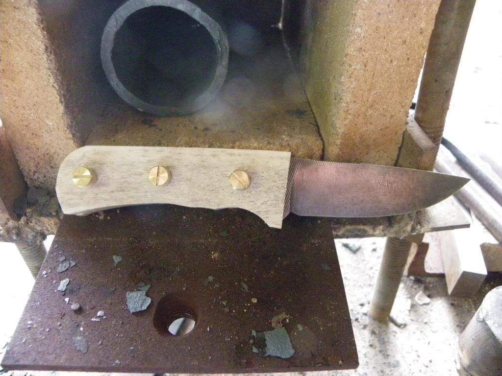
I like to fabricate knives from old files.
Had a friend ask me to make one for his dads birthday in June. I had to stop workin on my 51 f5 to get it done
He supplied one of his grandfathers files and some Elk antler for the handle.
..
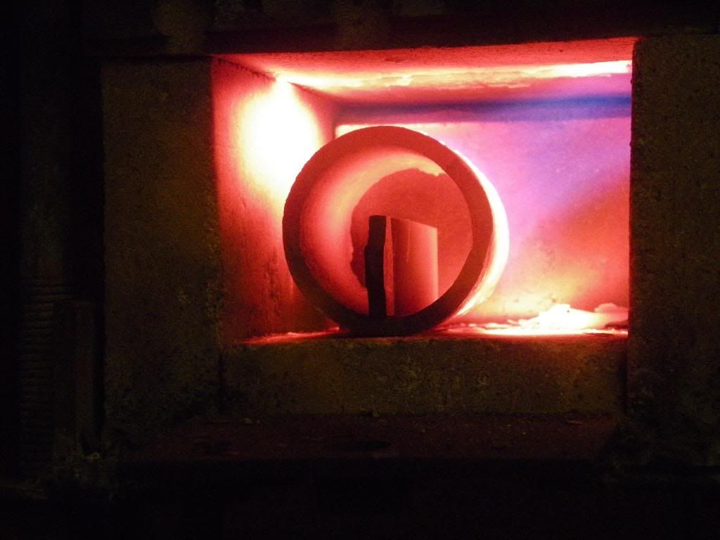
.File went into the kiln to anneal it- make it softer again.
and I built the kiln too.
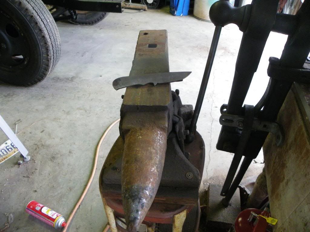
.after a lot of grinding I ended up with the rough shape.
.
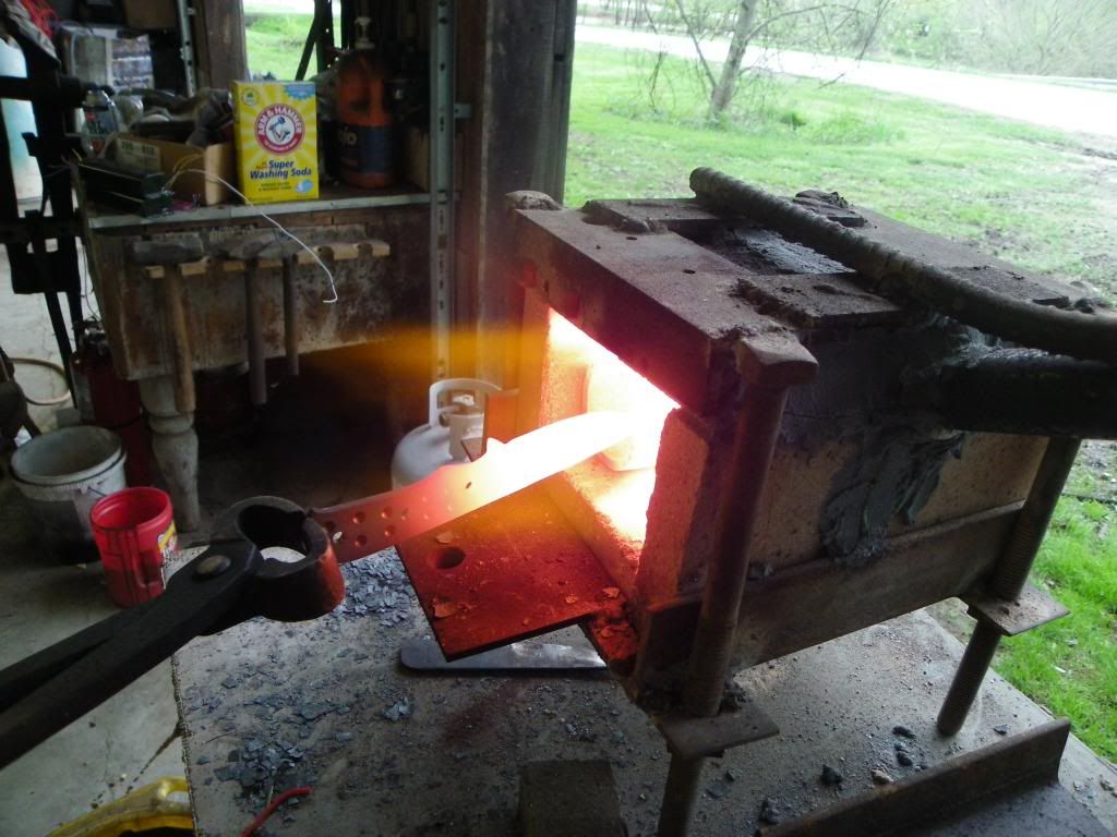
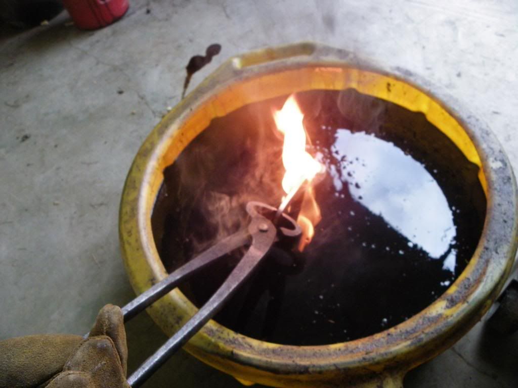
.When I am mostly done with the profile and blade angle it goes back into the kiln then a rapid quench in oil to make it hard again
.
.
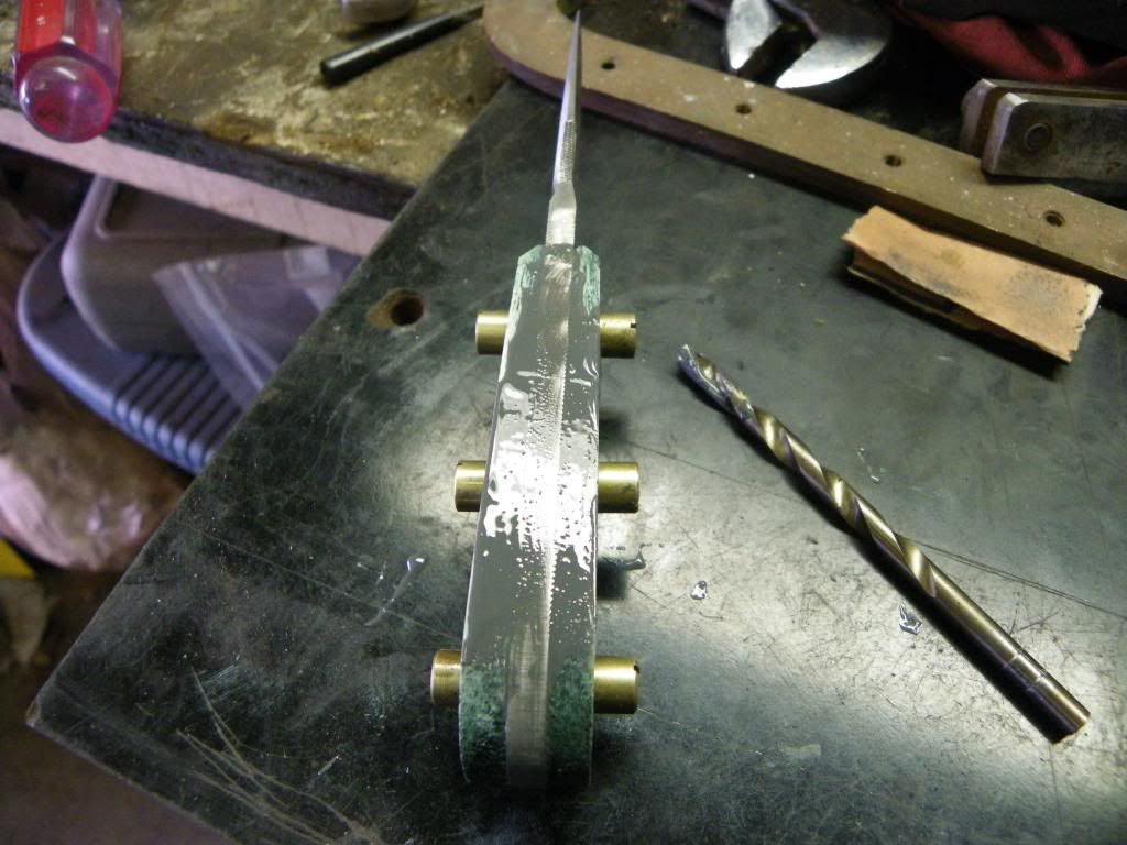
..Then to work on the handles and a perfect fit.
.
.
.Stabilized and dyed the antler handles and epoxied them to the blank
..
.And after lotsa sandin and polishin a knife is born
Whallla
Lots of inspiring fab work on this thread!
Here's a transmission holding fixture I built last week. I found some ideas on the internet, and also added a mounting plate to bolt it to my engine stand.
Very sturdy and works like a charm!
Of course, the engine stand was already occupied and I didn't want to buy another, so I had to fab up an engine storage stand first. I made it so that I'll be able to bolt the transmission up without interference.
Been a while since a contribution has been made to this thread so here is my low buck contribution.
I originally picked up a generic bearclaw and striker stud set at one of the local car shows. I don't recall the exact price but was something like 35-40 dollars.
Card board templates made.
Used the template to mark off area to cut out of door and began surgery.
Transfer template to metal.
Spot welds.
Finish weld and grind.
DA and check final fit of latch.
I used 3/8" plate to make a mount for the striker stud and drilled it to mount in the stock location which gave me the ability to adjust the striker.
I actually made the striker stud mounts first and used their location to determine where to locate the latch mechanism.
This the second time of fabricating a replacement panel using a Shrinker and Stretcher from Eastwood company. I think I did a fair job on it and thought it was good enough to share. This is under the rear doors of a panel truck I guess you would call it a sill plate? Top side was good but under side was really sad.
The under side of the rear door sill on my 51 Panel truck
Test fitting one of 4 pieces in making a repair panel
Three main pieces that form the two edges of the replacement panel
Fitting the pieces in place and preparing to make the final fill piece.
Haven't been on here for quite some time, although i have been lurking a little.
Since having started my own shop i just don't get the time.
But, i thought i might post a couple pics of my project shop truck, my 49 COE.
Its now on a Isuzu SBR frame and fitted with my favourite engine, a Lexus quad cam v8.
The body is now directly on the frame without the usual subframe between the body and frame, so sitting MUCH lower.
I will try to add a couple pics showing the new hood latch panel and L/H inner guard panel and will add some more when i start doing the planned 56 dash. cheers John
This the second time of fabricating a replacement panel using a Shrinker and Stretcher from Eastwood company. I think I did a fair job on it and thought it was good enough to share. This is under the rear doors of a panel truck I guess you would call it a sill plate? Top side was good but under side was really sad.
The under side of the rear door sill on my 51 Panel truck
Test fitting one of 4 pieces in making a repair panel
Three main pieces that form the two edges of the replacement panel
Fitting the pieces in place and preparing to make the final fill piece.
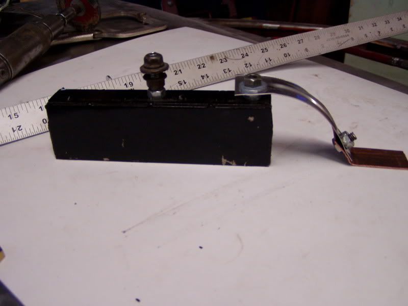
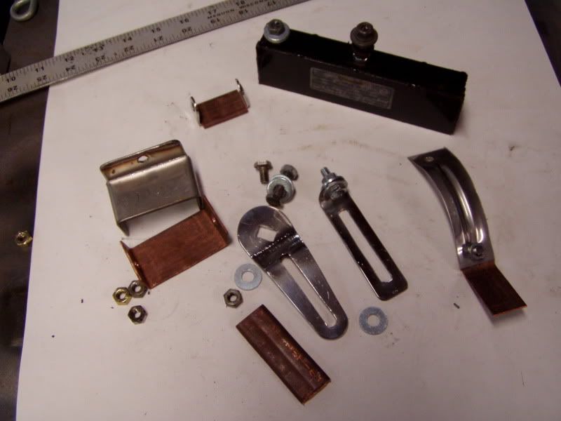
I use it to hold my new panels flush while I spot weld, but be advised that your welds will look really screwed up due to the strong magnet pull playing with the arc. I pull it off as soon as I get a few spot welds in place.
I also use this magnet to hold my copper backup when I'm trying to prevent blowing holes on thin sheet metal. Really handy for closing up small holes in firewalls. I made a variety of attachments that bolt to the magnet which allow the magnet to be placed away from the weld.
Hi, just reading through all these great posts, i thought ide share my fan shroud project. i searched around trying to find something i could modify, just couldnt find anything close. Soooo......
mounted plywood to radiator to find center ect...
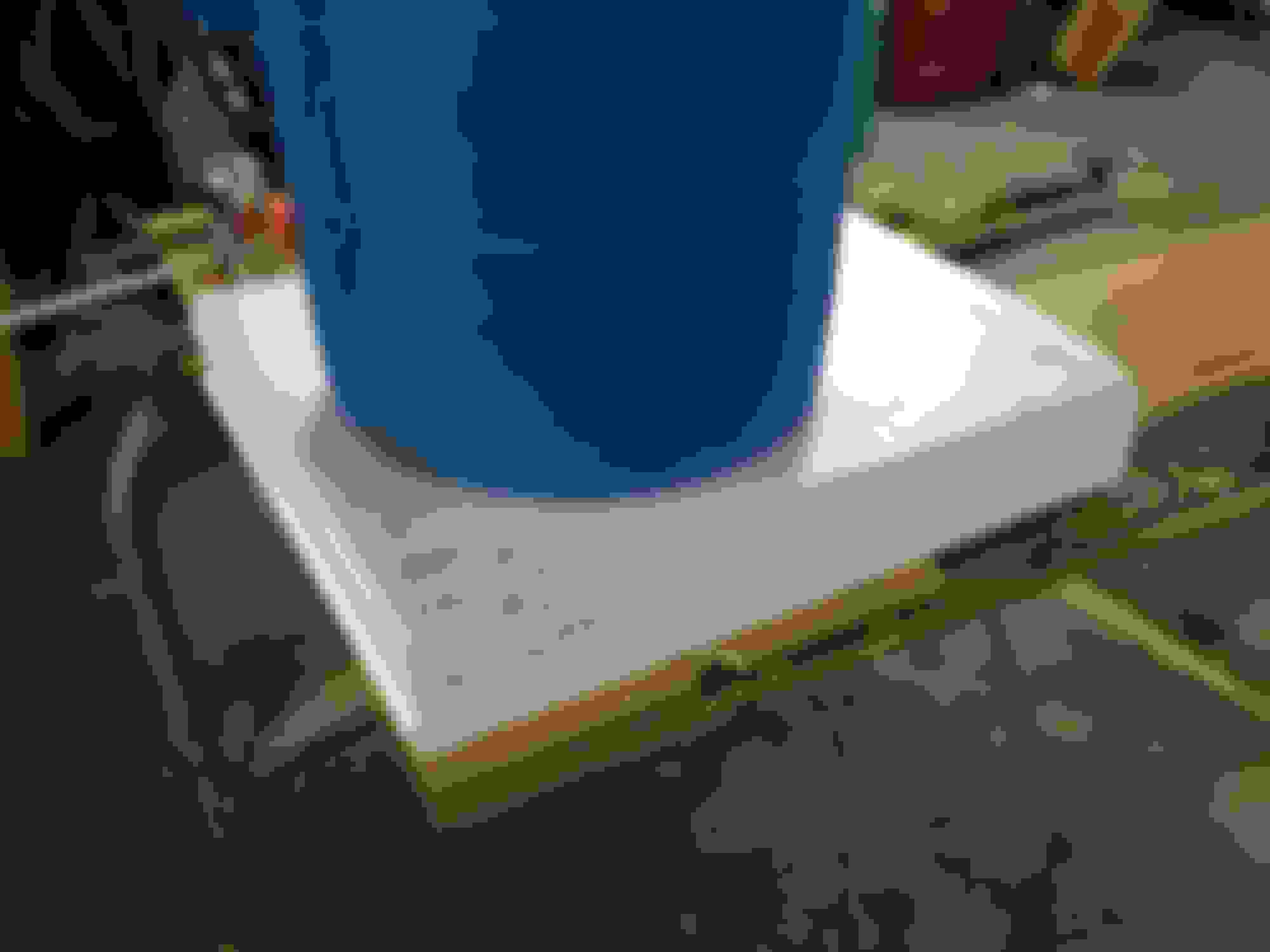
glued Styrofoam couple layers thick that overlapped plywood area
had to extend some
used the router to set the inner cavity of the shroud
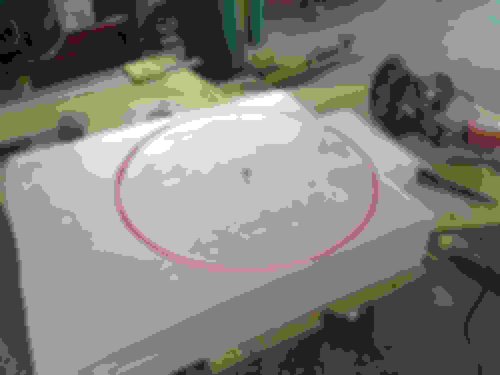
cut away the waste, and started shaping it with sandpaper and blocks
checked for fit...
decided to cover the foam w/ plastic so the resin from the fiberglass wouldnt eat it up... look close and ull see that i grabbed the wrong can of spray adhesive... sprayed a coat on before the plastic, turned around to see my form melting like the wicked witch... decided to rebuild it with some carboard and blue tape instead of starting over
few layers of cloth... air cleaner housing just keeping opening round
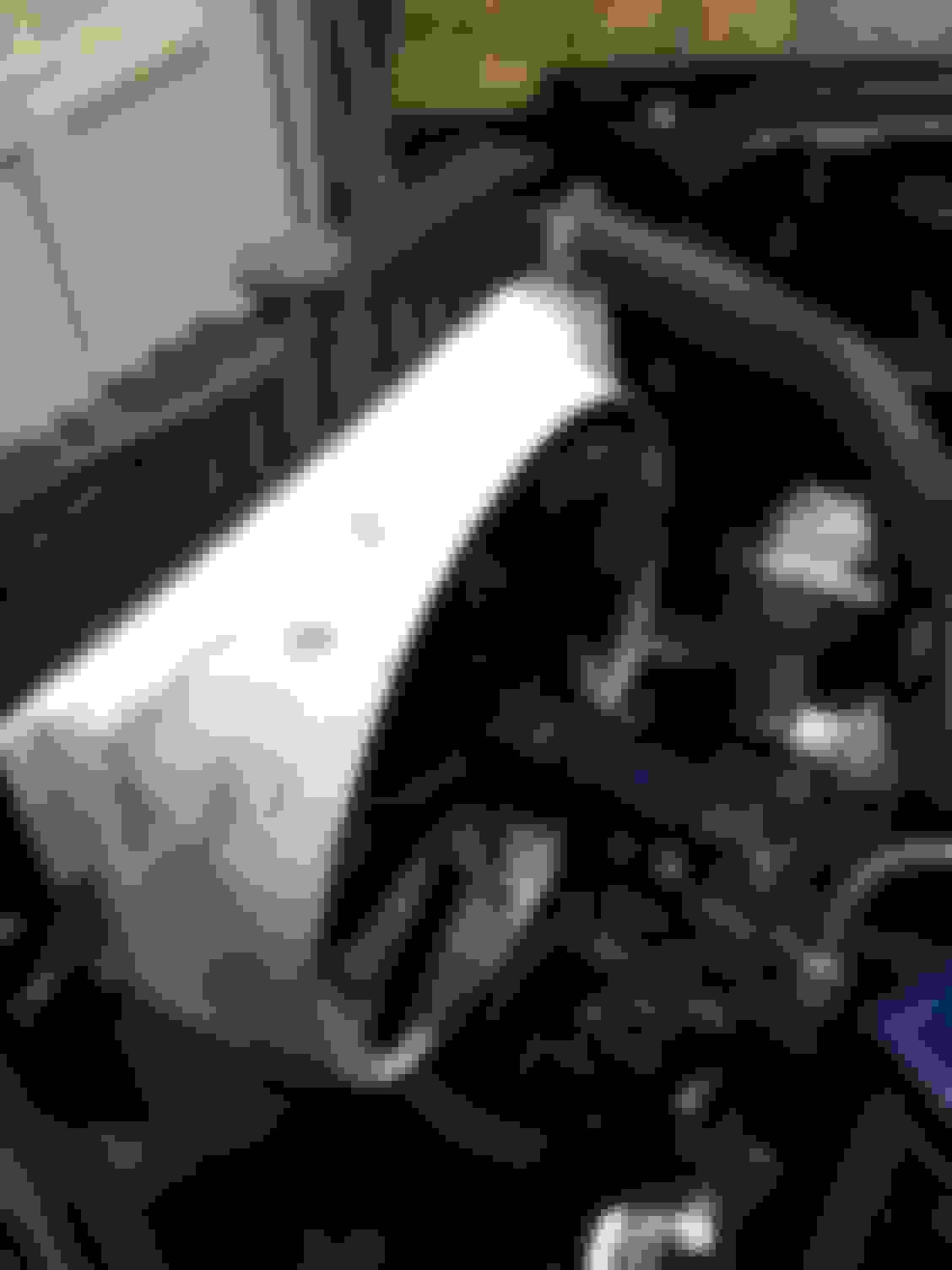
peeled off the form and trimmed up a bit
test fit with fan on... then i trimmed back to get right amount of fan exposed
fair amount of filler due to my form melting from the wrong glue.... GRRRRRRR
 04-28-2014, 08:53 PM