My 55 F-100 Project
#46
 11-30-2012, 09:36 AM

Hi Ax, good to see that your looking over my shoulder,hehe.
I do plan on boxing the frame all the way from the core support cross member to the intermediate cross member whitch will support the CV IFS superbly. By boxing this entire zone of the frame it locks the IFS to the sway bar. thus balancing frame losding.
Gary
I do plan on boxing the frame all the way from the core support cross member to the intermediate cross member whitch will support the CV IFS superbly. By boxing this entire zone of the frame it locks the IFS to the sway bar. thus balancing frame losding.
Gary
#47
12-04-2012, 02:04 PM
1995 T Bird IRS
Ok, so the basic installation of the IFS is done, minus some new points to ponder that AX has brought my attention to and will deal with before I button the front up.
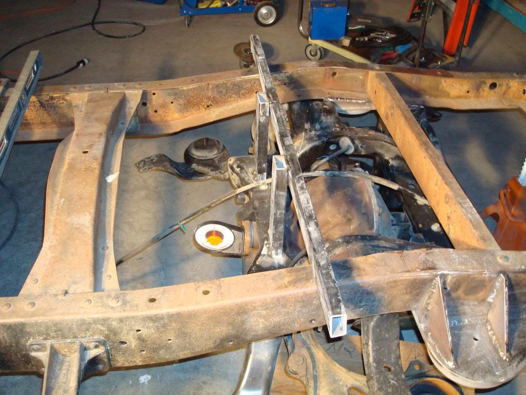
But My IRS is sitting here on the floor begging me to install it, so I did.
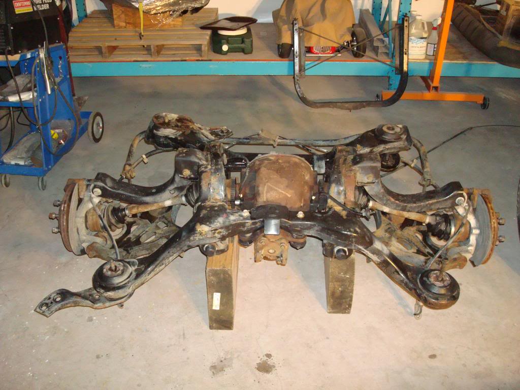
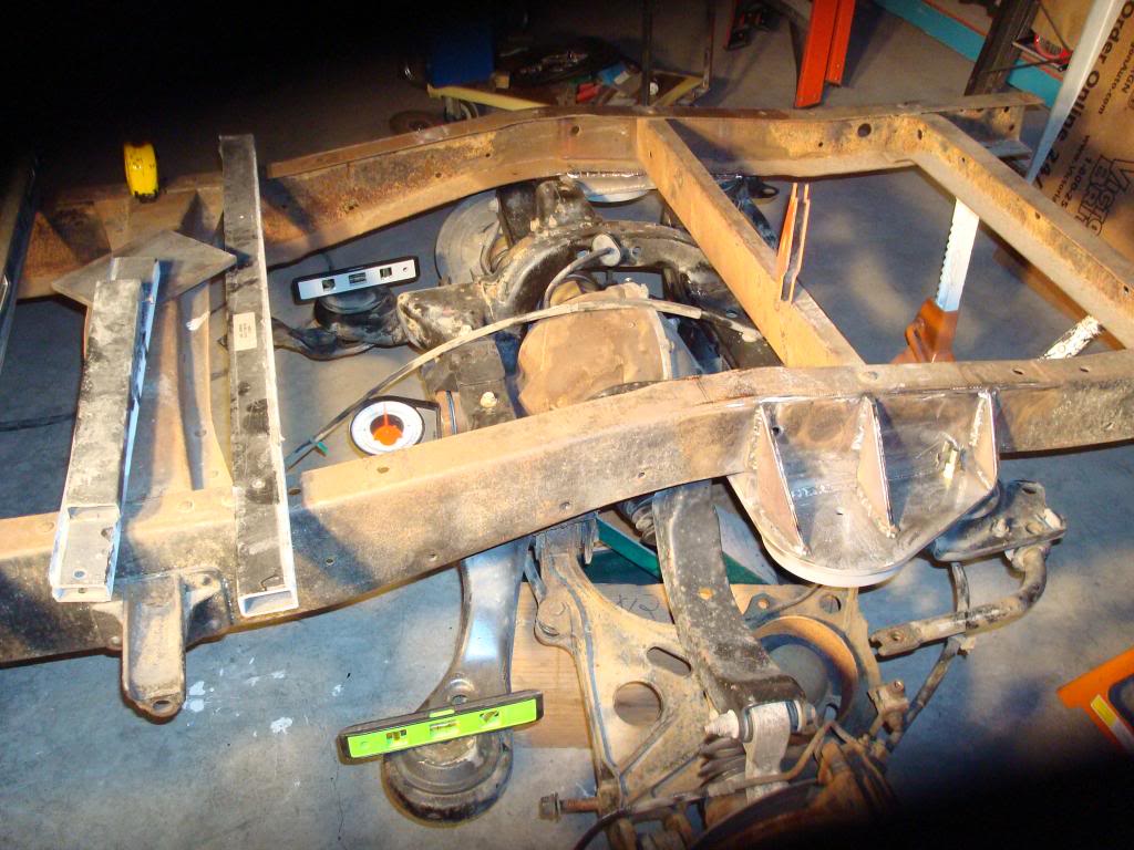
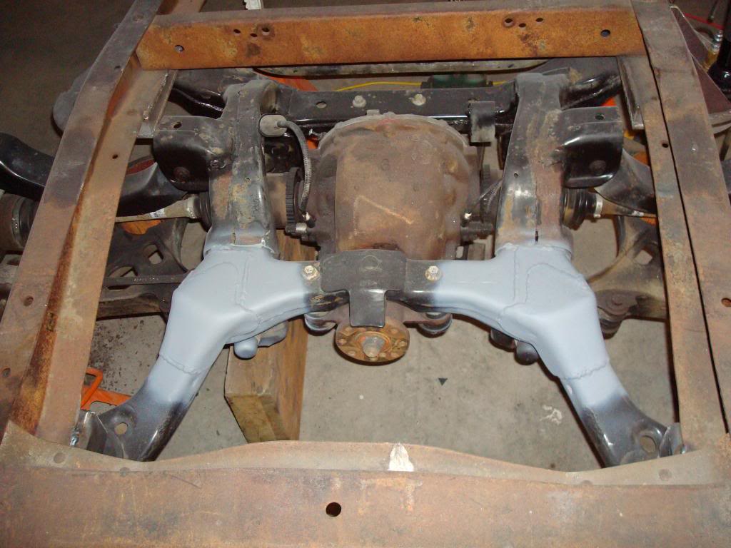
Front view of the system. It mounts to the frame via 4 elastromeric mounts, one at each corner of the "K" frame.
Also note the the forward mount points are much wider than the rear mounts, this places them out side the frame rails by about 4 inches.
When jacked into place, the rear mount bolts are just outside of the frame rail on either side, I can live with that
But, I hate having the front mount extending outside of the frame, something will have to be done to correct this problem.
But My IRS is sitting here on the floor begging me to install it, so I did.
Front view of the system. It mounts to the frame via 4 elastromeric mounts, one at each corner of the "K" frame.
Also note the the forward mount points are much wider than the rear mounts, this places them out side the frame rails by about 4 inches.
When jacked into place, the rear mount bolts are just outside of the frame rail on either side, I can live with that
But, I hate having the front mount extending outside of the frame, something will have to be done to correct this problem.
#48
12-04-2012, 02:35 PM
IRS continues
After looking at and discarding team 321's installation kit (for several reasons), I decided to build my own installation kit.
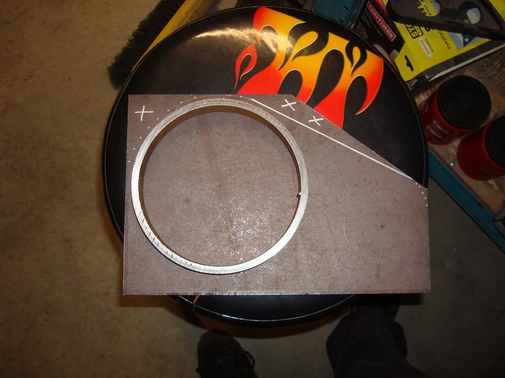
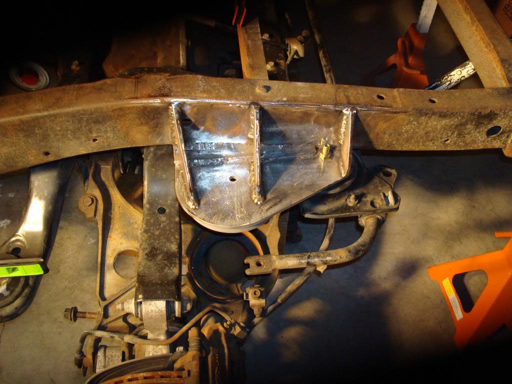
Bottom view of mount plate bank.
I would use a single plate to mount the system at the rear and also form the upper spring perch with a spring cup. Just as team 321 did.
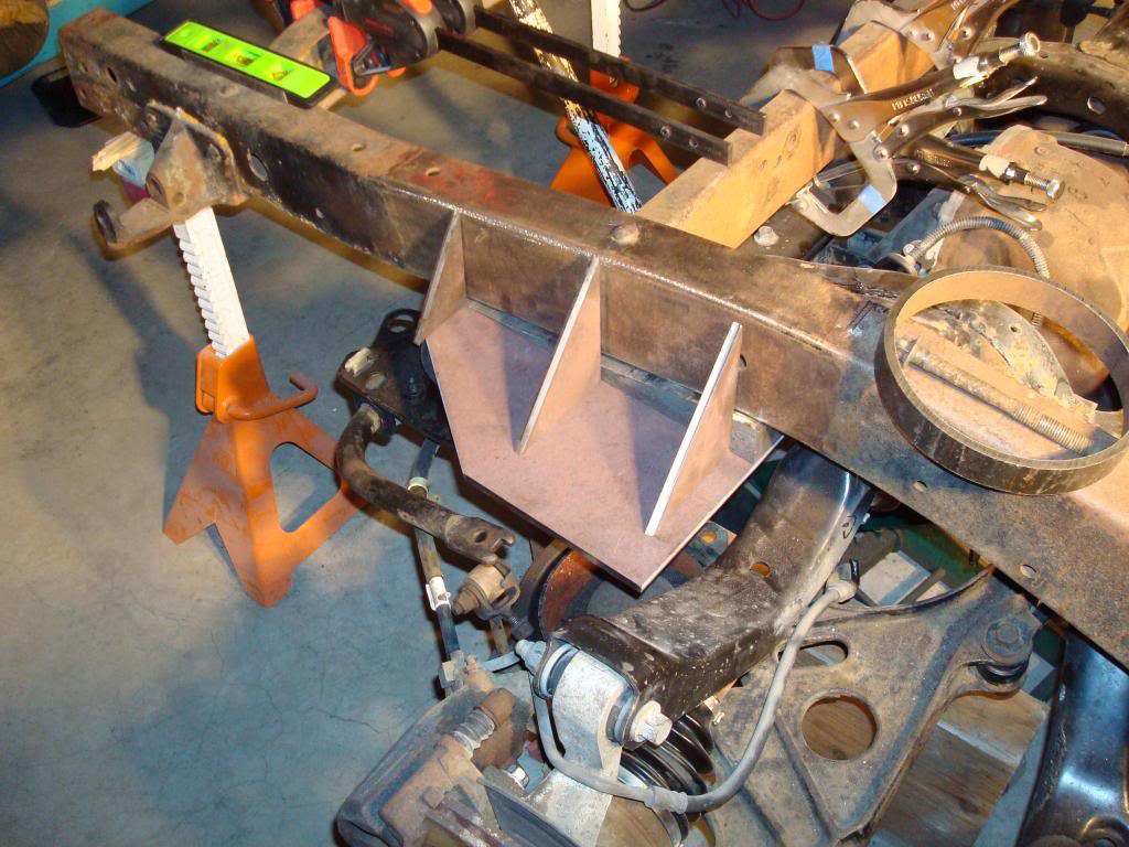
And will use multiple gussets to support the load, yet I will not cut out the frame cross member as team321 did.
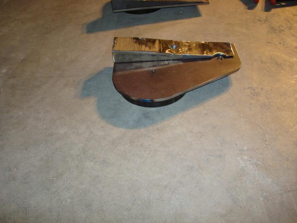
To keep from cutting into the frame I decided to do the same thing I did up front and that is to fabricate a radius block to level out the rear mount to the frame.
Bottom view of mount plate bank.
I would use a single plate to mount the system at the rear and also form the upper spring perch with a spring cup. Just as team 321 did.
And will use multiple gussets to support the load, yet I will not cut out the frame cross member as team321 did.
To keep from cutting into the frame I decided to do the same thing I did up front and that is to fabricate a radius block to level out the rear mount to the frame.
#49
12-04-2012, 02:50 PM
IRS continues on
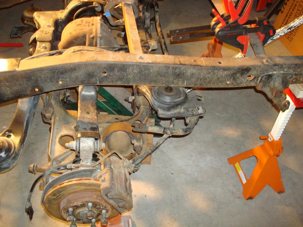
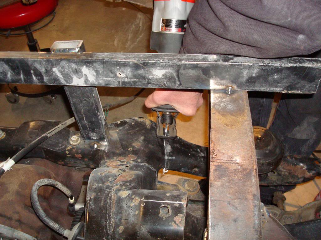
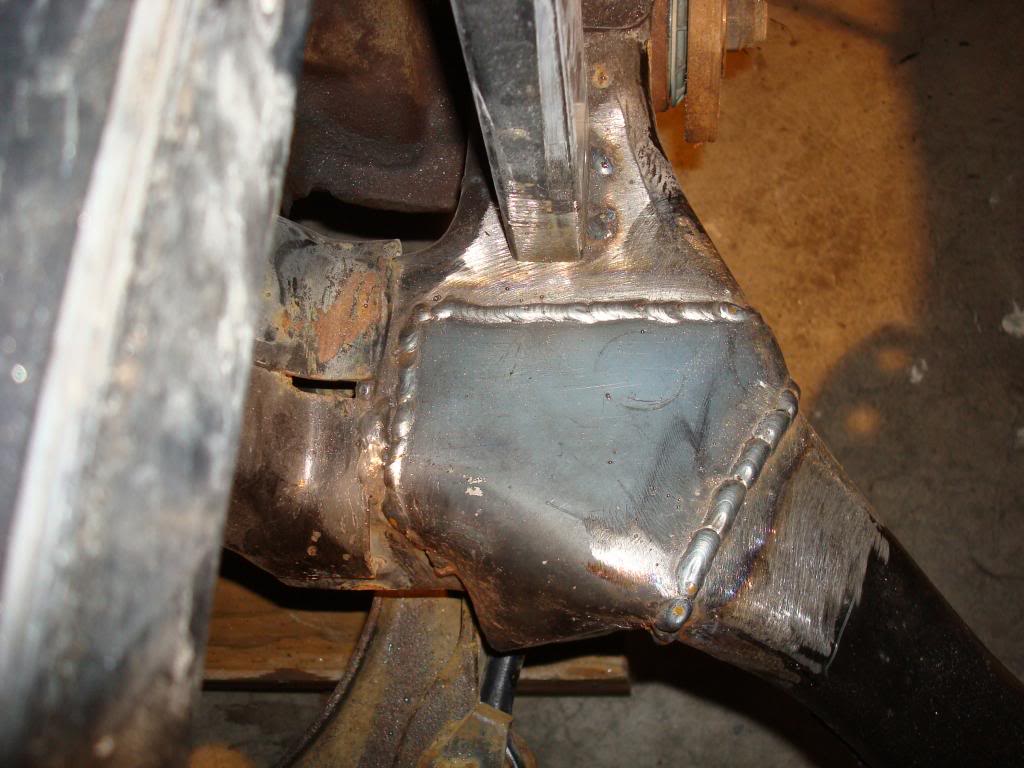
So, after fabbing up the rear mounts it was time to tack that part of the puzzle together.
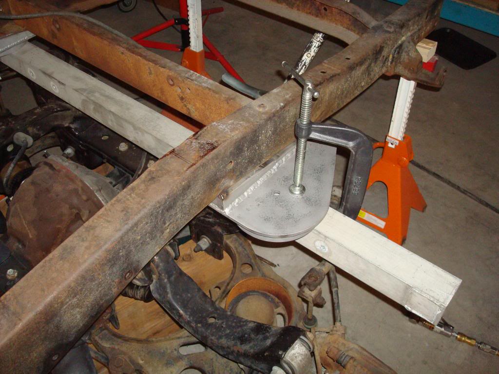
The two rear mounts were clamped in position, checked for level and tacked in place. Then a cross beam was clamped between the two mounts and the two mounts were tapped into alignment from side to side. Then I completed tacking things in before finally stitch welding it all in solid.
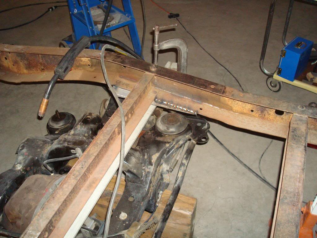
Again, I took my time and applied short stitch welds from side to side until it was solid.
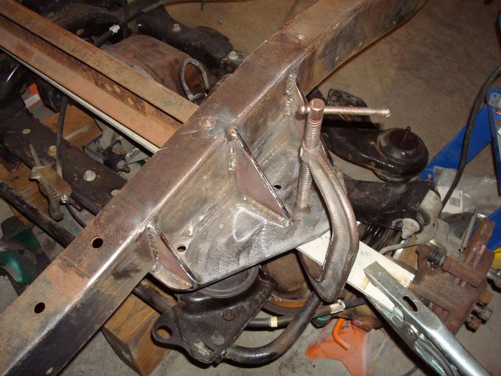
The next step was the addition of the gusset plates, I must have done something right during the initial welding because they all fit snug and true against the mount and frame.
Then the IRS was bolted up to the rear mounts and torqued into place, it was time to begin figuring out the front mounting arangement.
The two rear mounts were clamped in position, checked for level and tacked in place. Then a cross beam was clamped between the two mounts and the two mounts were tapped into alignment from side to side. Then I completed tacking things in before finally stitch welding it all in solid.
Again, I took my time and applied short stitch welds from side to side until it was solid.
The next step was the addition of the gusset plates, I must have done something right during the initial welding because they all fit snug and true against the mount and frame.
Then the IRS was bolted up to the rear mounts and torqued into place, it was time to begin figuring out the front mounting arangement.
#50
12-04-2012, 05:20 PM
Cargo Master
#51
12-04-2012, 08:08 PM
#52
12-04-2012, 08:15 PM
IRS front mounts begin
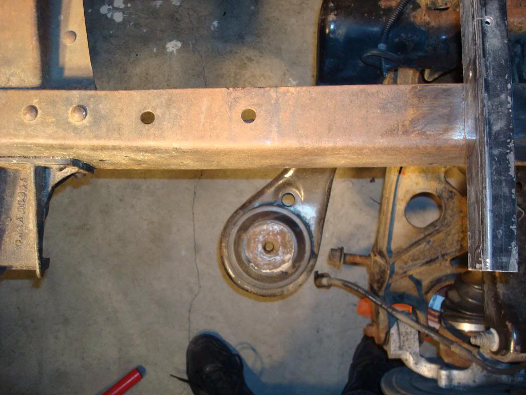
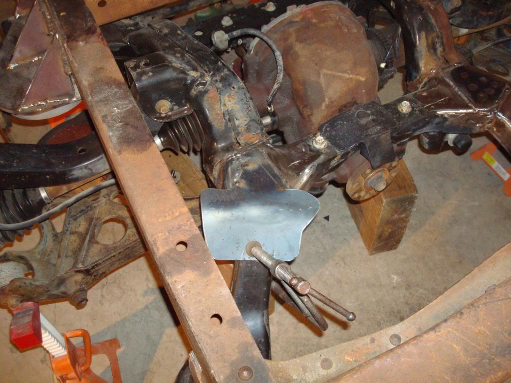
OK, so the rear mounts are in and the IRS is bolted in tight, but the fronts are still swinging free.
So I jack the unit up until the mounts are level, then I checked the pinion angle to ensure that its within spec.
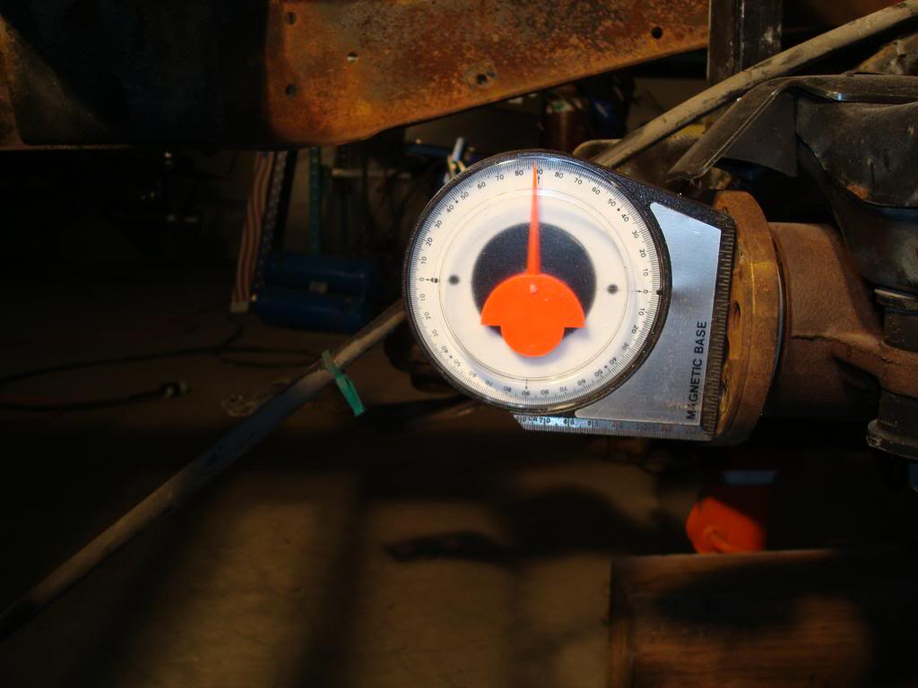
With the mounts level the pinion angle is right where I want it, a positive 2 degrees.
With the rear end right where I want it, I weld it in so it can't move around during the next phase of my insanity.
And that crazy voice in my head tells me to cut off the front mount legs.
So, I follow that voice and cut off both front mount legs,,,no going back now.
So I jack the unit up until the mounts are level, then I checked the pinion angle to ensure that its within spec.
With the mounts level the pinion angle is right where I want it, a positive 2 degrees.
With the rear end right where I want it, I weld it in so it can't move around during the next phase of my insanity.
And that crazy voice in my head tells me to cut off the front mount legs.
So, I follow that voice and cut off both front mount legs,,,no going back now.
#53
12-04-2012, 10:16 PM
front mounts
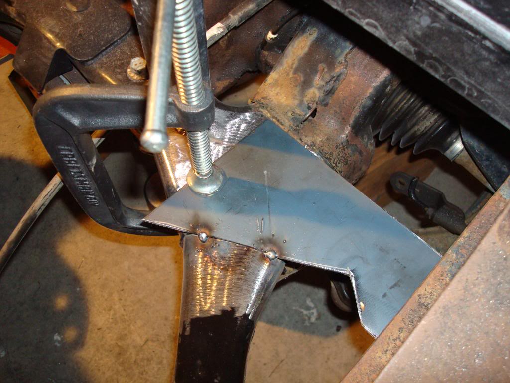
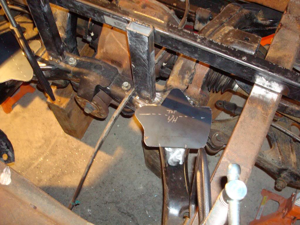
So, with the mounts cut off I begin moving them from here to there trying to figure out how to tuck them under the frame when my buddy suggests that I try the left one on the right and vs versa,,,,they lined up almost perfectly. All I needed was a drop mount to attach them.
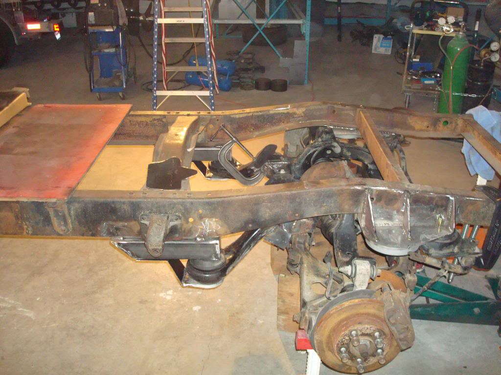
I began by building a lower frame mount from 3 inch box tubing and tacking them in place. Then I had to notch cut the bottom of the IRS mount arms to lock over the stub that I left on the IRS K frame and again, tacked it into place.
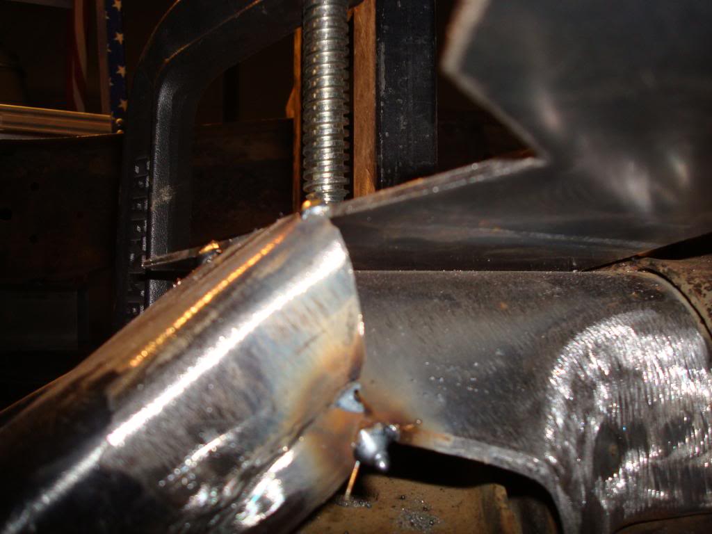
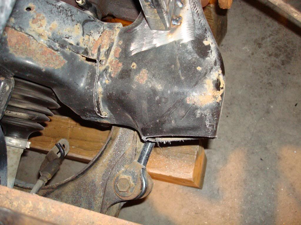
Next I began the process of building a new knuckle to replace what I had hacked off.
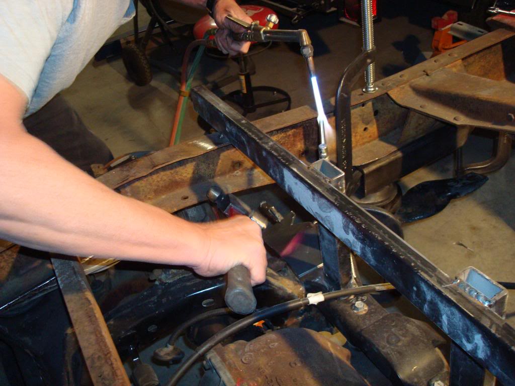
I started with 1/8 plate and began tacking it in.
Then with a bit of heat and a hammer I rolled the plate around the knuckle stub, stitch welding it in a section at a time until the top plate was secured.
I began by building a lower frame mount from 3 inch box tubing and tacking them in place. Then I had to notch cut the bottom of the IRS mount arms to lock over the stub that I left on the IRS K frame and again, tacked it into place.
Next I began the process of building a new knuckle to replace what I had hacked off.
I started with 1/8 plate and began tacking it in.
Then with a bit of heat and a hammer I rolled the plate around the knuckle stub, stitch welding it in a section at a time until the top plate was secured.
#54
12-05-2012, 09:12 AM
IRS knuckle repair
The mount arms are now reattached but I want them to be stronger than they were before I hacked them off so I decide to rosete weld and fish plate the newly welded joints.
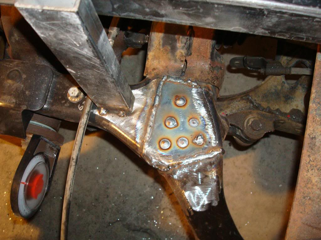
I start by drilling through the new knuckle plate and rosete welding it solidly to the original K frame.
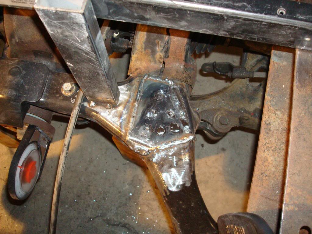
Then I smoothed out all the welds where my fish plates would go.
I made the fish plates from more 1/8" plate so they would overlap the welds where the mount arm was reattached.
Then the slow process of heat forming, tack welding, and more heat forming took place.
Just like the first plate used to rejoin the arm I had to work small sections at a time until they mated smoothly, then thry had to be tacked there before I could begin working the next section.
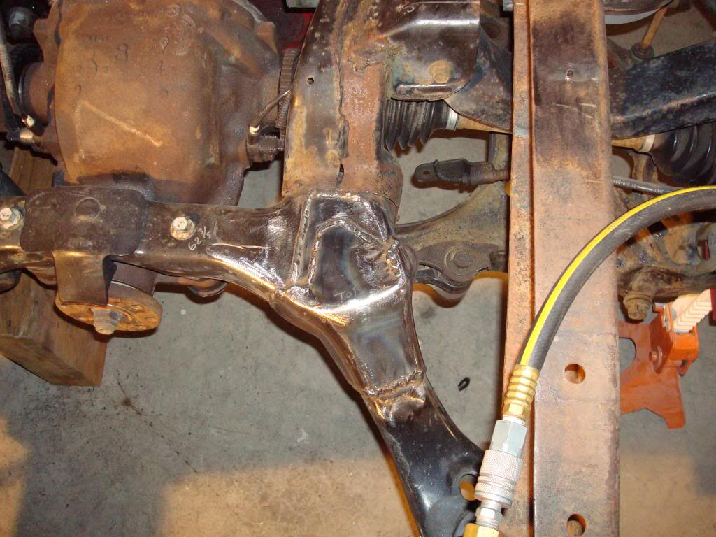
But finally the fish plates were molded to the new knuckle and welded in solidly. Again I rosete welded the fish plate to the knuckle repair (no pic)
After a bit of weld smoothing and a little primer the K frame almost looks factory again. Once the IRS is disassembled and flipped over I have to repeat this entire exercise on the bottom side of the K frame before it gets to final paint.
I start by drilling through the new knuckle plate and rosete welding it solidly to the original K frame.
Then I smoothed out all the welds where my fish plates would go.
I made the fish plates from more 1/8" plate so they would overlap the welds where the mount arm was reattached.
Then the slow process of heat forming, tack welding, and more heat forming took place.
Just like the first plate used to rejoin the arm I had to work small sections at a time until they mated smoothly, then thry had to be tacked there before I could begin working the next section.
But finally the fish plates were molded to the new knuckle and welded in solidly. Again I rosete welded the fish plate to the knuckle repair (no pic)
After a bit of weld smoothing and a little primer the K frame almost looks factory again. Once the IRS is disassembled and flipped over I have to repeat this entire exercise on the bottom side of the K frame before it gets to final paint.
#55
12-05-2012, 09:52 AM
#56
12-05-2012, 10:04 AM
Elder User
Join Date: Oct 2011
Location: Neosho, MO
Posts: 777
Likes: 0
Received 0 Likes
on
0 Posts
#57
12-05-2012, 10:04 AM
Thats what this whole forum is about, the sharing of information and ideas. I haven't been here very long but I have picked up some kewl info and differant ways to skin the cat.
So I figured that I needed to share my ideas too,,,,as crazy as they may be,,hehe.
And then there is AX looking over my shoulder, slapping me when I stray off course.
So I figured that I needed to share my ideas too,,,,as crazy as they may be,,hehe.
And then there is AX looking over my shoulder, slapping me when I stray off course.
 I approve!

#59
12-05-2012, 11:39 AM

#60
12-05-2012, 08:54 PM