When you click on links to various merchants on this site and make a purchase, this can result in this site earning a commission. Affiliate programs and affiliations include, but are not limited to, the eBay Partner Network.
I'll suggest that you ask if they can dynamically balance what you are going to run with then. Preferably from the pulleys to the pressure plate. Especially if you're going to make it rock and roll. But, you probably already know that.
Edit - Are you going with a serpentine belt?
It was a good suggestion for sure, he suggested to static and dynamic balance the engine to ensure the most horsepower.
The belts are going to be the same stock setup for now. However I have to still figure out exactly how my power steering pump off the TCI frame is going to mate together with my engine system.
Edit: No worries about the power steering pump not going with power steering anymore going old school Manuel.
Last edited by Mattie2294; 08-19-2013 at 09:48 PM.
Reason: Revised Build
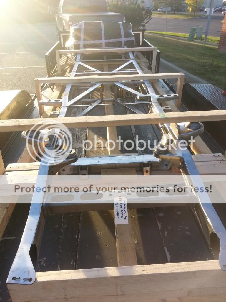
Well good evening to everyone out there. I got a call yesterday from Watson's Hot Rod Parts informing me that my frame had just arrived.
Now I have just got back home after picking up my TCI frame.
They really have done a great job with there frames and if your looking to do an extensive suspension upgrade a few extra thousand and a complete frame could be a great option.
It really makes it hard to have to wait to get started full force back into my project. Anyways here are some pictures of the frame. (My camera died so sorry they are not that great)
Nice and shiny. Of course, now you're going to miss out on the fun of driving the pins holding your original shackles in place out.
Can't wait to see the engine. Mine didn't come with one, so going the 302 route was an easy decision.
Mike
Holy cow... I just found this thread, and I had to subscribe. Rebuilding a '52 F3 myself, started in March '13. Hope I finish it while I can still drive!!
After a lot of busy months I finally got back on the Ford project train I setup my frame today (pictures to come laer);however, I have ran into some parts of un sure if I'm not sure where they go. They are labelled r sway bar. Can any help explain or upload pictures?!?! Thanks you!!!
Thank you sir!!! I have a few more questions that hopefully someone can answer I'll post later on hopefully. 85 percent done as of today will be finished tomorrow!
Started by un-packing all the materials and spreading them out.
Then I got the frame all cut loose and blocked up level.
Then got started by adjusting all the 4-link bars to 1/2" extended on each one. Got all the bars installed and lifted the rear end into place using a floor jack.
Once it was lifted I installed all the bars and set the offset on each side to be the same. (Not exactly sure what the procedure is for setting your offset and getting the rear end completely true??? Not really an issue now since I will be disassembling the entire thing for paint and reassembling before the final product is finished.)
Lastly I installed the sway bars and put on some mustang winter wheels to roll the frame around for now.
That was it for the rear end. I have started the front end as well and will post pictures later today!
** After I flipped the brakes to there correct side and snugged everything down it all seems to fit into place nicely.
***Now to fix camber angle are there special plates to push the top slotted connect outwards (move the top of the wheel out so they don't bow in?) or do I just use the extra washers that I have and add until camber angle is correct?!?!
Hopefully the setup I have started is correct. Let me know if you see anything out of place (Other than the brakes that were on the wrong side haha) ..
I am doing the finishing touches and trying to get the manual rack installed; however, there is two large holes in the rack that I think should have a rubber or some sort of fitting. Below is all the parts I was given. I think if it is just a bolt and a washer on either side the rack will have some much room to move back and forth. Does anyone have any information or pictures of this setup?!?!
EDIT ***Found the answer I am missing a rubber that is to be placed inside the rack.
Last edited by Mattie2294; 06-24-2014 at 01:21 PM.
Reason: Solved the problem
I began installation of the front end by installing the lower and upper control arms. As well as installing the shock into the slot of the lower control arm.
I have heard many horror stories about springs and coils so I went out and bought a spring compressor from the local NAPPA (Just my luck it was on sale).
Now I tried compressing the spring enough to fit it into place and I literally had it compressed almost to a single block of steel. Then I realized that you can pull on the top of the shock and the bolt will extend out (This makes it so you only need to compress the spring a little bit).
**BIGGEST TIP DO NOT COMPRESS THE SPRING TO A SOLID BLOCK OF STEEL PULL ON THE SHOCK AND EXTEND IT OUT FULLY FIRST.**
Needless to say the second side went alot more smooth. Lastly I placed the brakes and snugged everything tight.
I then connected the tie rods and got the wheels close to centered up.
Now I placed the rack on the frame and snugged it up using the bolt and washer (I will need to remove and install the rubber bushing when I receive it, since my package didn't include them). Another rookie mistake was placing the rack before fining its center point. Finding the center while it is on the frame is alot more difficult then it would have been to do it on a bench.
**TIP 2 FIND THE CENTER OF YOUR RACK BEFORE YOU PLACE IT ON THE FRAME**
Either way we managed to find the center by turning the wheel all the way to the left, then all the way to the right. Adding the two and dividing it out equally between the two wheels.
Everything was mock fit and all that was left was final adjustments. Took some frame to wheel measurements using a straight edge and a square to get the wheels running true.
I have not set camber yet since I am not sure if I should use washers and add them until the camber is correct or if there is a special way to do it.
Everything was complete, however the alignment would need to be checked and re checked. I have to disassemble the frame anyways for paint so I just got everything close.
Now that I have the frame completely mock built it was time to disassemble the 52's front end. I started by removing the front wheels to get access to all the bolts (FYI: Yes there was a lot of bolts holding the front end on). I sprayed all the bolts and let them sit in PB Blaster for a few minutes to hopefully loosen them up. Then I removed all the bolts using various techniques (Bolts from 52 are not a smooth to come off as new shiny ones). In the end I got the front end removed after a few hours per panel.
Slid the grill ontop of the new frame and look at that ride height (Yes darkside may have got me on that one).
Kept the ball rolling last night and removed the cab from the 52's body. I removed:
-4 front bolts from cab to frame
-2 back bolts from cab extension plates to frame extension plates
-The entire steering box. Another option was to unbolt the wheel and pull the steering column out the bottom but it would have to be blocked up or held way higher.
-The shifter
-The parking brake
-Peddle plates removed to allow the peddles to pass through.
Once all these were removed I pulled a sling from door to door and lifted with the Bobcat.
Now my next step is to clean up all the parts I am going to be using and inventory everything I need to purchase. A company here where I live is going to swap my old frame and parts for a discount on some of my new ones. I plan on dropping it off mid to late August and picking up everything I need.
FYI: Engine is in progress and I am planning to go mid to late July to pick it up.
You're really coming along! To answer a couple of your questions, use washers to set your camber. Use a long bolt or rod of the correct diameter through both ends of all the 4 link bars, this way they are all exactly the same length. If you measure the fist one then insert the long bolts and adjust each remaining bar so it slides over the bolt.
 08-12-2013, 07:04 PM