Ford F150 1980-1997: How to Replace Dana 44 Front Axle Seals/Bearings
Bad bearings or leaking seals in the front of your F-150 4x4 can be a real annoyance, or worse, leave you stranded on a trail somewhere. It is time consuming, but you can replace them all at home with not too much effort.
This article applies to the Ford F-150 4x4 (1980-1997).
A failing front axle wheel bearing manifests itself with excessive noise and vibration, but it may first manifest itself as a leaking seal. Typically there’s a humming noise that changes in time with the road speed of the truck. It may also be louder when you turn to the right or the left. With the tire lifted off the ground, a bad bearing can be diagnosed by rocking the wheel in and out from a six-o’clock and 12-o’clock location (not side to side).
Ford equipped the F-150 with Dana Twin Traction Beam (TTB) independent front suspension (IFS) axles on 1980 to 1997 model year 4x4s, which comprised three F-150 generations. Whether you plan to replace the front seals, or front seals and front bearings, you’ll need to first determine the proper seals and bearings in your F-150. This can prove difficult, as these changed quite a bit over the three generations of truck—often mid-generation, and sometimes mid-model year. As shown in this article on a 1994, from 1980 to 1997, Ford’s F-150 Dana 44 spindles used one needle bearing to support the outer axle shaft, and two different spindle seal types for the front axles. During this same time period, Ford also used four different spindle nut configurations.
It’s a good idea to make sure you can return any replacement parts you buy if you find your truck was in the middle of a part-size changeover, or somehow ended up with non-model-year replacement parts.
Materials Needed
- Ratchets and torque wrench
- Sockets set including 13/16-inch, 1/2-inch, 8mm, 11/16-inch, 1/4-inch
- Snap ring pliers
- A pair of small picks or jeweler’s screwdrivers
- Allen wrench set
- Bearing packer
- Grease gun (with high-temp grease)
- Hammer
- Pry bars
- Race and bearing installation kit (rental)
- 2/3 jaw slide hammer set (rental)
- Anti-seize lube
- Brake cleaner (don’t get this on bearings)
- PB Blaster
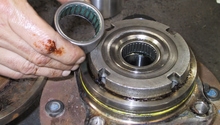
There are three bearing sets for each side. Going from the outside in, there’s an outer wheel bearing, then an inner wheel bearing that sits outside the spindle but inside the hub. The third bearing is the spindle bearing that sits inside the spindle itself. The wheel bearing set includes the race, which is a tapered stainless steel ring that the bearing sits in. The spindle bearing doesn’t include a race.
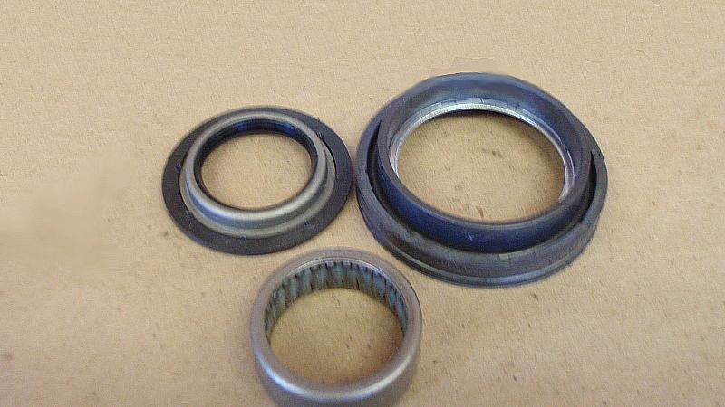
Figure 1. Spindle bearing and seal set. 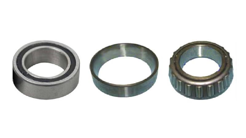
Figure 2. The wheel bearings and races.
Begin by lifting the truck and taking off the wheels, and brake calipers.
- Loosen lug nuts with the wheels on the ground.
- Jack up the front of the truck, and place in jack stands.
- Remove the front wheels.
- Take off the brake calipers and set aside.
- The front brake caliper removal is detailed here: Ford F150 Caliper Removal.
Step 1 – Remove the hub
- With an Allen wrench, remove the six cap screws holding the hub cover of the locking hub in place.
- Pull the hub cover straight off.
- With a Phillips screwdriver, remove the single screw on the face of the hub assembly, while holding the spring-loaded inner lock ring in place.
- Use snap right pliers and remove the retaining ring on the end of the axle shaft.
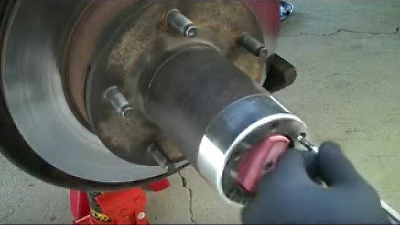
Figure 3. Remove hub cap screws. 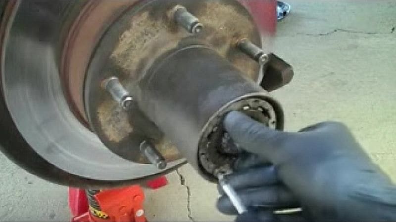
Figure 4. Remove cross-head screw. 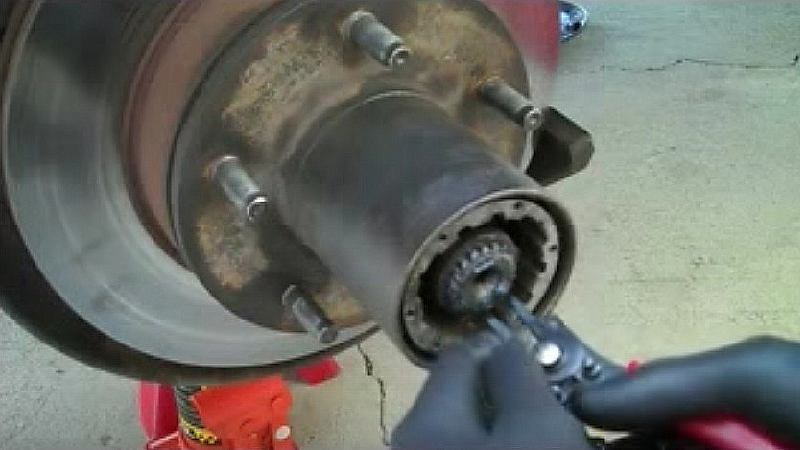
Figure 5. Remove the snap ring from the end of the axle shaft.
- With two small pick tools, remove the large outer retaining retaining ring in the recessed area of the hub housing.
- With one tool, pull one end out of its groove while pulling outward with the other tool.
- Reinsert one or more of the hub cap Allen screws back into the locking hub body finger-tight.
- Pull the hub assembly out with the Allen screws.

Figure 6. Remove the large retaining ring. 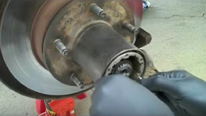
Figure 7. Pull the hub assembly out of the spindle opening.
Step 2 – Remove the hub/rotor assembly
- Use the proper spindle lock nut socket for your truck and unscrew the lock nut until it’s loose in the hub.
- Use needle nose pliers to remove the lock nut (if the lock nut is already loose, it may have been the source of the bad wheel bearing).
- Some lock nuts are a two-piece construction that may separate during removal. Once removed, slide the two halves back together and set them aside.
- Before removing the hub assembly, use some tape (Figure 10) to prevent the outer wheel bearing from falling out when the assembly is removed pulled off the spindle—especially if you’re hoping to repack and reuse the outer bearing.
- Slide the hub off and carefully set it aside.
- Clean the axle shaft off with a rag.
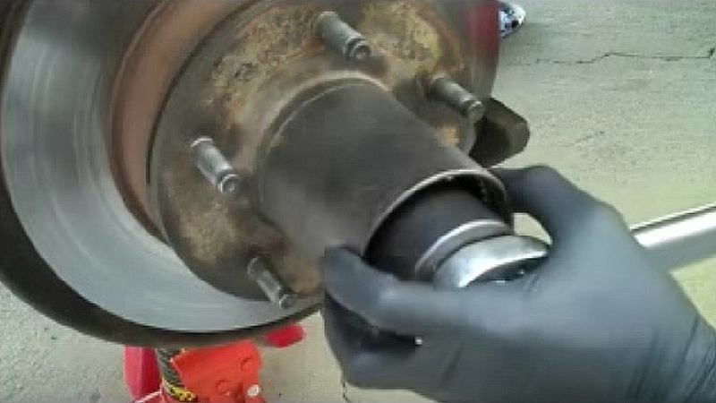
Figure 8. Remove the spindle lock nut. 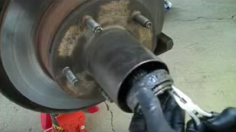
Figure 9. Pull the lock nut from the spindle opening. 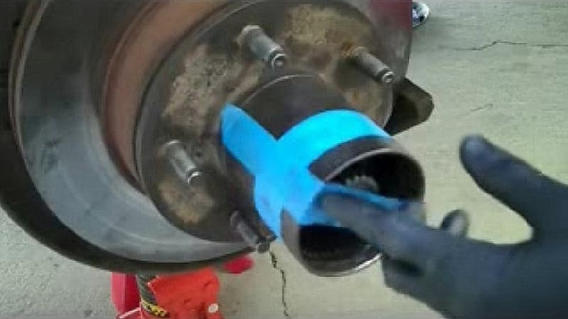
Figure 10. Tape over the spindle to retain the bearing as you pull it off.
Step 3 – Remove ABS sensor and sensor shield
- Remove the ABS sensor by first unbolting it with an 8mm socket from the rear of the knuckle near the universal joint.
- From the front of the wheel, push the ABC sensor through to the back.
- If it’s stuck, use a socket and hammer to gently tap the ABS sensor from the front to loosen it, then push through.
- Carefully set or tie the ABS sensor out of the way behind the backing plate.
- Using the 6mm 12-point socket from the backside of the knuckle, unbolt and remove the ABS sensor shield.
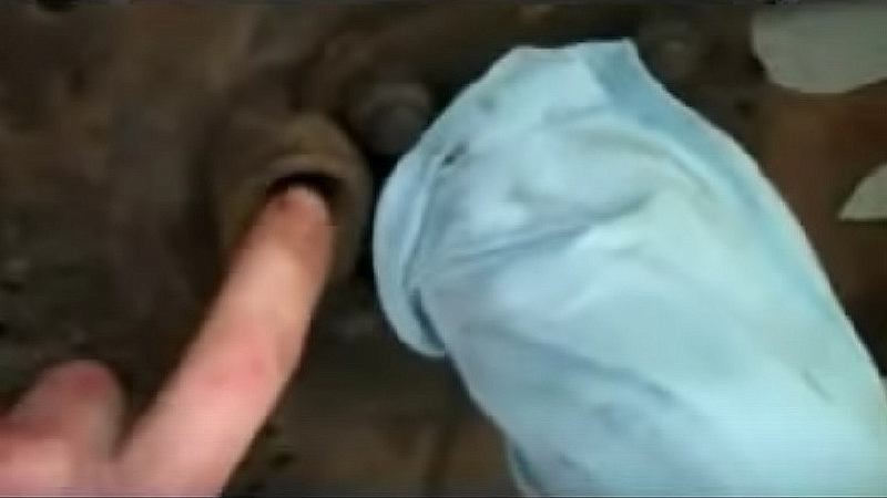
Figure 11. Push the ABS through to the rear. 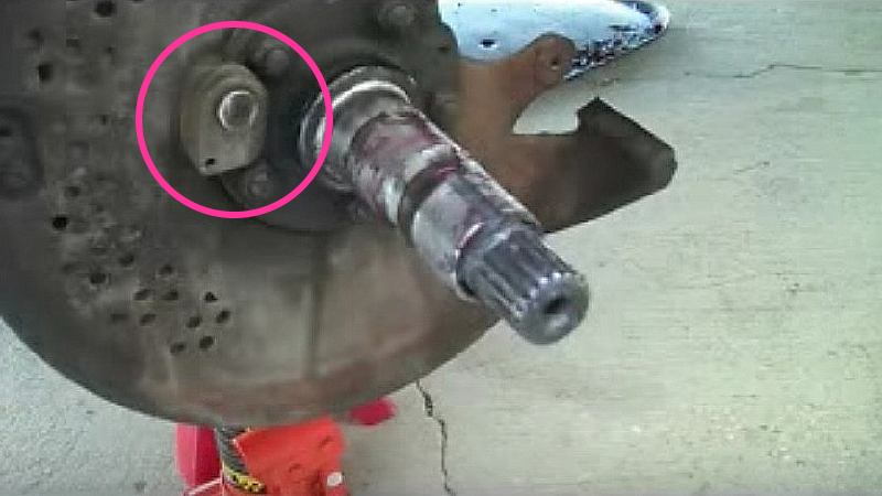
Figure 12. ABS sensor shield.
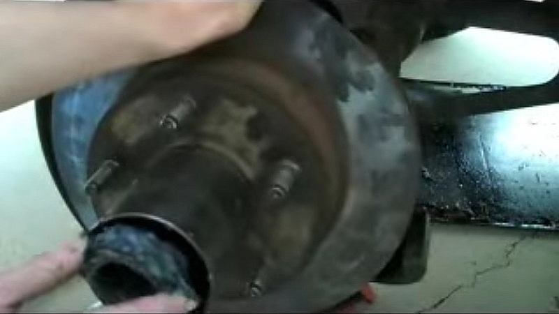
Step 4 – Remove the spindle
- Using an 18mm socket and breaker bar, loosen the spindle nuts and set aside.
- Take care not to damage the spindle during this operation.
- Screw the 4WD spindle puller into the front of the spindle hand-tight.
- Thread the slide hammer into the spindle puller and give it a few backward hits.
- Pull the spindle out.
- If the axle shaft tries to come off with it, just push it back into place.
- Carefully place the spindle aside, then clean off the axle shaft’s surface.
- Wrap the axle shaft with a shop rag to keep it from getting damaged, as the U-joint now allows it to hang free.
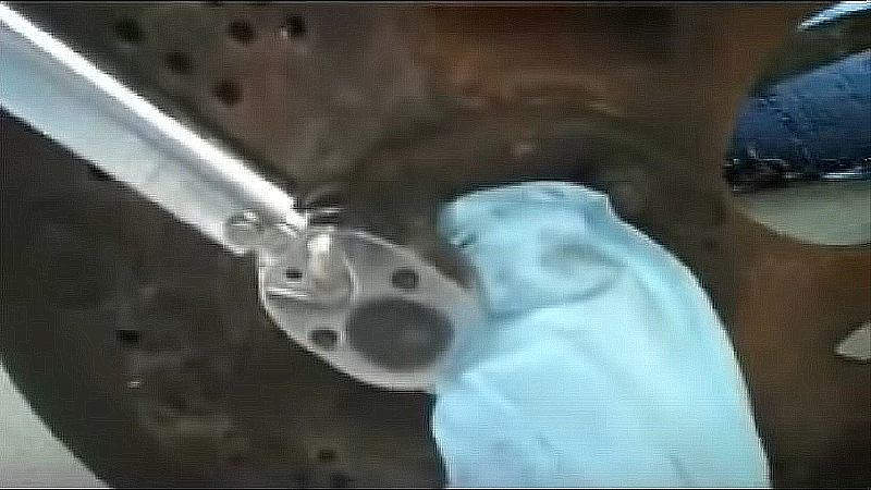
Figure 13. Take the five spindle nuts off. 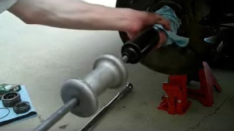
Figure 14. Remove the spindle with the spindle puller and slide hammer.
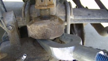
Step 5 – Pull the spindle bearing and seal
- Pull the spindle bearing and seal out from the rear of the spindle with the slide hammer.
- To do this, first place towels on the floor to protect the threads in the neck of the spindle.
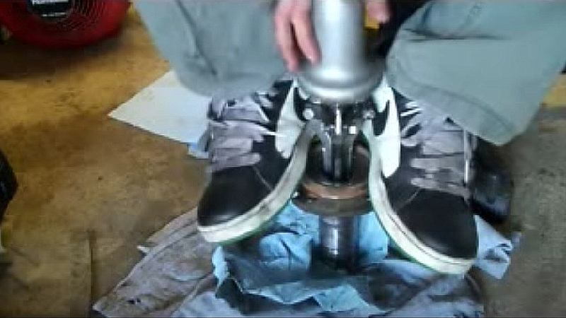
- Attach the three jaw puller to the backside of the bearing, making sure that the jaws have a solid grip on the bearing race.
- Give the slide hammer a few sharp strokes while standing on the spindle to hold it.
- With the spindle bearing and spindle bearing removed, clean out the inside of the spindle.
- Put a very thin layer of new grease around the neck of the spindle’s rear opening where the new bearing will sit.
Step 6 – Replace the spindle bearing and outer seal
- Wipe down the new spindle bearing to get the rust inhibitor off of it.
- Place the bearing into the spindle opening with the numbers on the bearing’s rim facing outward.
- Select an appropriate size bearing driver, and with a rubber mallet, drive it in, making sure it goes in straight.
- Stop the pounding when the bearing seats on the inner ridge.
- Find a bearing driver in the proper size for the seal and drive the seal in.
- Make sure the seal is seated just below flush with the edge.
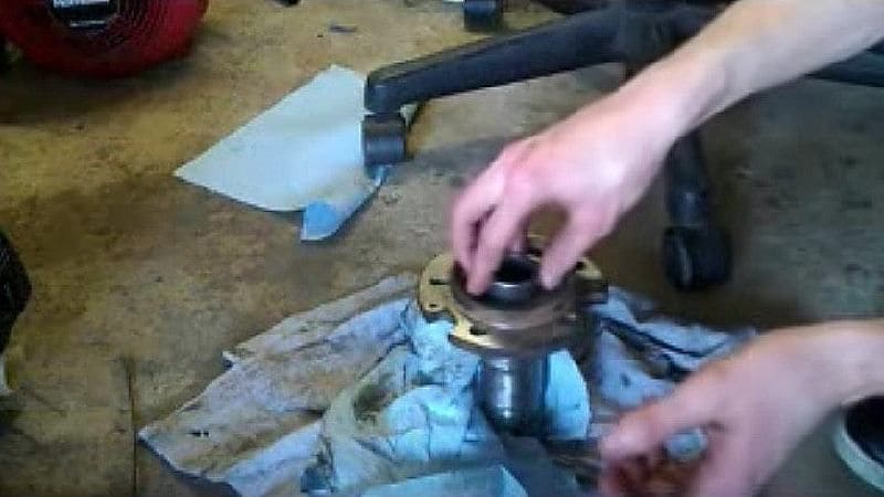
Figure 16. Replace the spindle bearing with a new one. 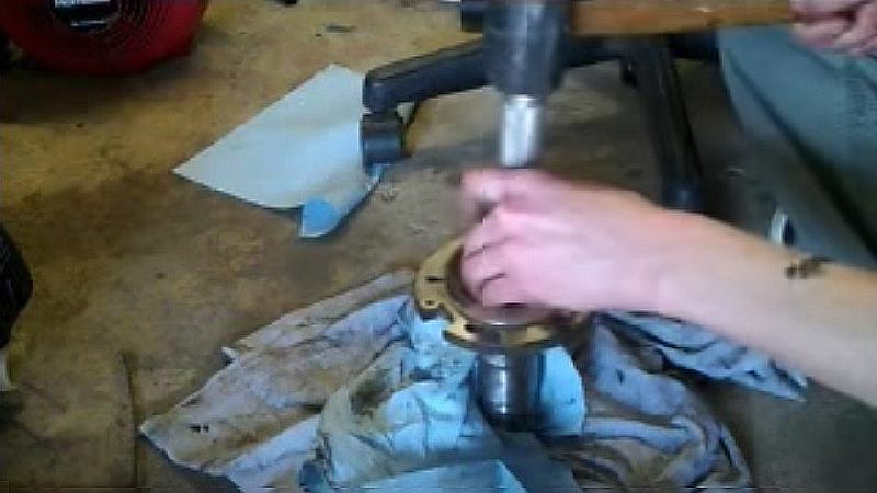
Figure 17. Use the bearing driver to seat the spindle bearing. 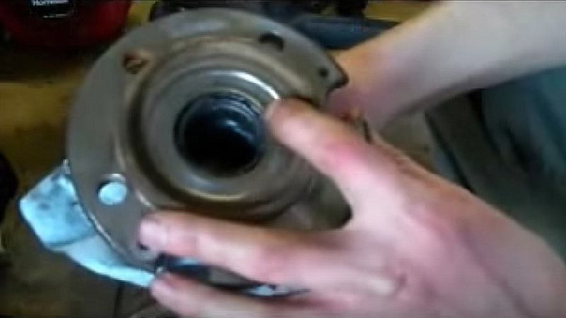
Figure 18. Spindle seal seated in back of bearing.
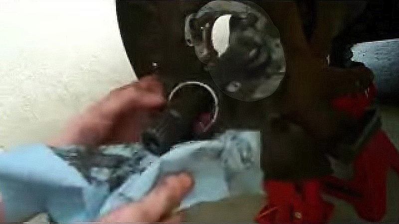
Step 7 – Remove the inner spindle bearing seal
- Take care not to scratch the axle shaft surface when pulling these parts.
- Pull the inner spindle bearing seal out and off the axle.
- Careful use of channel-lock pliers can help break this seal loose from the axle shaft.
- Clean, then apply a small amount of grease to the machined surface on the axle shaft where the new inner seal will seat.
Step 8 – Replace the inner spindle bearing seal
- Slide the new inner spindle bearing seal into place down the axle shaft by hand.
- The plastic end goes first and the metal inner ring faces out.
- Drive in until it hits its raised stop location.
- Clean the mating surfaces of the back of the spindle and wheel hub, and apply a very thin later on anti-seize on it.
- Next, from the rear of the spindle, wipe some grease into the bearing, on the axle shaft and on the axle shaft’s spindle bearing location.
Step 9 – Replace the spindle
- Replace the spindle on the axle shaft.
- Make sure the notch cut-out for the ABS sensor is over the ABS mount location.
- The notches should be outlined on the mounting surface of the hub from years of use.
- If the vehicle didn’t have ABS, the keyway cut into the outer neck of the spindle should be mounted facing upward.
- Carefully slide the spindle back into the axle shaft to its seating position against the hub.
- Replace and tighten the nuts in a star-pattern.
- Be certain the the inner spindle seal is positioned and seated properly.
- Torque the spindle attachment nuts to 40 lb-ft (54 Nm).

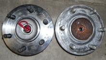
Step 10 – Remove the wheel seal
- With the rotor placed on a shop rag to protect the end of the hub, remove the wheel seal from the rotor.
- Here a large flat head screwdriver is being used to lever it out.
- Pry the edge of the seal against the hard edge of the rotor.
- Work your way around the seal and it should pop out.
- When that seal is out, use the screwdriver to pry the wheel seal out.
- With this seal removed, pull the inner bearing out by hand.
- Get the outer bearing from under the tape on the end of the rotor.
- If reusing them, clean both the inner and outer bearings, then repack them with grease.
- Replace the inner bearing into the rotor and hub assembly with the split beveled ring in the same position as before.
- Carefully pound the new inner bearing seal into place with a hammer, and again using a circular pattern.
- Spread a thin layer of grease on the seal.
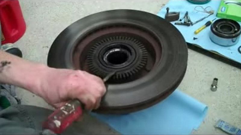
Figure 21. Using a screwdriver to pound off the wheel seal. 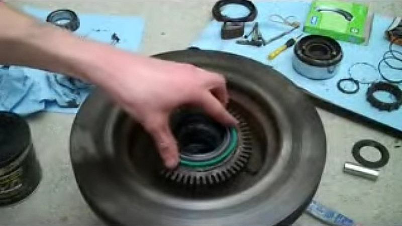
Figure 22. Replace the inner bearing into the rotor and hub assembly and pound in a new inner bearing seal.
Step 11 – Replace the ABS sensor and shield
Put a bit of anti seize at the location of the ABS sensor and in the mounting hole. Bolt in the ABS sensor and then the ABS sensor shield from behind.
Step 12 – Replace hub and rotor assembly onto spindle
- Reinstall the hub and rotor assembly onto the spindle.
- Slide it back on carefully, making sure the rear seal re-seats on its sealing surface.
- Reinsert the outer wheel bearing.
- Grease up the spindle lock nut.
- Make sure the tab in the spindle lock nut is aligned with the notch cut in the spindle and reinstall.
- Carefully hand-tighten the lock nut with the socket, making sure the threads are properly engaged.
- With the torque wrench, tighten the lock nut to 70 lb-ft (95 Nm) of torque while spinning the hub and rotor assembly back and forth to fully seat the bearing.
- Now, back the nut off 90 degrees (one quarter turn) and re-torque it this time to 20 lb-ft (27 Nm).
Step 13 – Replace the hub assembly
- Place a light layer of grease on the hub body and slide it back into place.
- Because the seal is new, it will push the axle in, so grab it from the universal joint and pull it back out again.
- Replace the inner snap ring onto the end of the axle shaft with snap ring pliers.
- Reinstall the large outer retaining snap ring back in its recess.
- Reinstall the lock ring spring and lock ring having greased the splines a bit.
- Push the spring in and replace the Phillips screw.
- Finally, replace the hub lock cap.
Finishing up:
- At this point, clean both sides of the brake rotor thoroughly with brake cleaning fluid to remove any grease.
- Replace the brake caliper.
- Replace the wheels.
- Lower the truck to the ground.
- Take the truck for a slow test drive and listen for noises.
- Test the 4x4 hubs for proper locking.
You’re done.
Featured Videos: Spindle Bearings and Seals Replacement
-
Part 1
-
Part 2
Related Discussions
- Wheel and Spindle Bearing Replacement on Dana 44 - Ford-Trucks.com
- F150 and Bronco Front End Rebuild - Ford-Trucks.com
- Front Axle Bearings and Seals - Ford-Trucks.com
- Dana 44 Front Axle Bearings - Ford-Trucks.com