Engine swap wiring design.
#1
 01-03-2019, 12:51 AM

Engine swap wiring design.
Hiya 
I'm trying to stuff a Cummins turbo diesel into an old Ford truck... now I have lots of the swap figured out but the wiring portion.
Let me start by saying I know how to do this... by that I mean I have a basic understanding on what wires go where...but no idea in the best way they get there lol...
1----- First thing is fusable links... I'm going to be relocating everything under the hood... and the harness as is is mostly to long. Do I want to use fusable links again? Would some sort of fuse or breaker be better?
2----- I have my start wire that went to the old starter solenoid... if I was to use it how many relays could I switch from it? Do relays have a large enough draw where I could be limited to the number of them I could use with it? Do I need a relay to run my relays lol?
3----- My injection pump (not fuel pump) requires one relay... the injection pump and ecm also require constant on and key on power. Your thoughts on running the keyed power through a relay? I may have more keyed power in the old harness but maybe a relay would be better?
4----- Taking the fusable link question into account... what do I do with the alternator output? I may have to run a 200 amp alt because of the electric fans... so I'm guessing a mega fuse? What should I do about power distribution to the engine and its power needs? A single bolt power distribution? Battery and alt output to one side of mega fuse... then to some sort of power distribution box?
Keep in mind that I'll have several more relays for headlights, fuel pump and alarm... along with a 90amp fan controller which pretty much takes care of itself...
I really don't know what to do lol... if you have any pointers or products that would help please share I'd like to have something that at least looks semi professional lol
*EDIT*
I should add that I already have a relay box... I think its 6 relays with blade fuses. I haven't counted but I think I'll have at least 6 or more relays.
I'm trying to stuff a Cummins turbo diesel into an old Ford truck... now I have lots of the swap figured out but the wiring portion.
Let me start by saying I know how to do this... by that I mean I have a basic understanding on what wires go where...but no idea in the best way they get there lol...
1----- First thing is fusable links... I'm going to be relocating everything under the hood... and the harness as is is mostly to long. Do I want to use fusable links again? Would some sort of fuse or breaker be better?
2----- I have my start wire that went to the old starter solenoid... if I was to use it how many relays could I switch from it? Do relays have a large enough draw where I could be limited to the number of them I could use with it? Do I need a relay to run my relays lol?
3----- My injection pump (not fuel pump) requires one relay... the injection pump and ecm also require constant on and key on power. Your thoughts on running the keyed power through a relay? I may have more keyed power in the old harness but maybe a relay would be better?
4----- Taking the fusable link question into account... what do I do with the alternator output? I may have to run a 200 amp alt because of the electric fans... so I'm guessing a mega fuse? What should I do about power distribution to the engine and its power needs? A single bolt power distribution? Battery and alt output to one side of mega fuse... then to some sort of power distribution box?
Keep in mind that I'll have several more relays for headlights, fuel pump and alarm... along with a 90amp fan controller which pretty much takes care of itself...
I really don't know what to do lol... if you have any pointers or products that would help please share
I'd like to have something that at least looks semi professional lol*EDIT*
I should add that I already have a relay box... I think its 6 relays with blade fuses. I haven't counted but I think I'll have at least 6 or more relays.
#2
01-03-2019, 07:53 AM

1. I personally like fusible links. They are small and easily insulated and incorporated into the harness. They are only there to protect the wiring from some unknown catastrophe like a accident. The only other time they blow it seems is from owners doing dumb things, like working on their alternator without disconnecting the battery first. Fuses and circuit breakers protect individual circuits from overload, and are located further downstream. The factory has slowly gone over to mega fuses in their vehicles, but they still use some fusible links also. If you decide to replace your fusible links with fuses or circuit breakers, they have to be pretty big and be the mega fuse style.
2. If you are talking about adding those 30 amp Bosch style relays, I do not think you would have enough room under the hood to mount enough of them to overload the circuit. Their coils draw very little current.
3. If you feel the original harness does not have enough power to run these circuits, then you do need a relay. Otherwise, just adding a relay to add one is just adding a failure point, the relay can go bad.
4.. In the old days they did not run any protection on some of the large wiring under the hood. If you purposely keep these few wires very short and protect them well, I do not see a problem with it. A 250 amp or so mega fuse is a very large fuse and you have to mount it somewhere out of harms way. And even then, you will have short pieces of wire leading to the mega fuse from the battery and the alternator that will not be protected. So it's judgement call. One other thing fuses cause, voltage drop. Fuses are a necessary thing sometimes, but they do introduce some voltage drop in the wiring.
Since you are adding a lot of electrical, and need to take advantage of a larger alternator, I think I would add a underhood fuse box. You can get smaller ones from the stores, or you can get larger ones from the junkyard under the hood of the newer vehicles. I am not sure what you are working on, but most Fords used a fender mounted starter relay (solenoid) and they always used this as a tie point for the battery, the alternator output and the feed to feed the truck's electrical. If you are going to keep this starter relay, you could use it as a tie point also like Ford did, and you could keep the original tie point and fusible link for the original harness, and then add another large wire to this point and feed the added underhood fuse box. From that underhood fuse box feed all your added circuits, leave the original Ford truck harness out of it, they barely made the original harness large enough to run the truck's original configuration.
#3
01-03-2019, 08:49 PM
Thank you sir!
I'm working with a 91ish ford f250.
so seeing as I'm not going to be using the old starter solenoid... what other ways can I distribute power?
I think the route is... power distribution to individual relay input to fuse to end of circuit? Is that right?
Thanks again for your help!
I'm working with a 91ish ford f250.
so seeing as I'm not going to be using the old starter solenoid... what other ways can I distribute power?
I think the route is... power distribution to individual relay input to fuse to end of circuit? Is that right?
Thanks again for your help!
#4
01-04-2019, 08:05 AM
Is there a particular reason you are eliminating the original solenoid? It does make a good tie point, and you would already have the wiring there from the neutral safety/ignition start to trigger the starter on your new engine. It would be used like Ford used it, lots of heavy wires on the one side that also go to the battery +, and a smaller wire leading off the other side going down to the solenoid on the starter. And then you have the small trigger wire from the neutral safety.
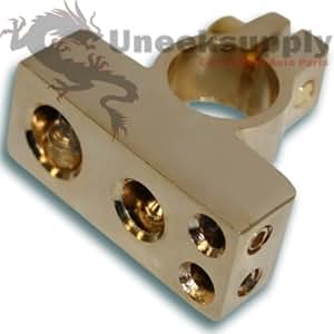
Otherwise, a stud mounted in plastic to make a tie point would be a option. You could also put it all on the battery terminal itself, I think the large stereo guys sell terminals for this. Here is an example;
Here's how the distribution goes;
Large wire from the battery, either very short and protected or a mega fuse mounted nearby, to the fuse box first. Then the fuse box is loaded with smaller fuses to suit each circuit. You might have some 30 amp circuits for some 30 amp relays, which would use 10 gauge wiring. If you have a heavier draw, you would have a heavier fuse feeding a larger relay using larger wire. Then after each relay, you keep the same size wire to feed that circuit. This way the individual fuses protect the relay and the wiring in that circuit.
Here is a large fuse holder that will hold two large fuses.
https://www.waytekwire.com/item/4601...1-Fuse-Holder/
Here's a smaller fuse block to handle smaller loads.
https://ceautoelectricsupply.com/pro...tion-products/
Here is a fuse block with the spot made into it for the relays already.
https://www.bp-automotive.com/produc...bution-center/
#6
01-04-2019, 12:10 PM
The Ford solenoid was just used as a large relay if that makes you feel any better about it. In other words in the original configuration, the start signal came from the ignition switch, through what ever neutral safety it had, and then wen to the fender mounted solenoid. So the original circuit just activated the solenoid, then the solenoid sent a small power signal down to the idi starter solenoid which actually does all the work at the starter. Some of those large starter solenoids on the diesels do draw some power, and all that power would not be going through the start switch wiring.
#7
01-05-2019, 01:51 AM
Thanks!
I understundethe how and why of the solenoid...
I'm formulating a plan now... thanks for your help
I'm thinking about using I think there called military battery ends? Solves the loss of the old starter solenoid doubling as a power distribution point and looks like a great solution when needing more than one wire to the positive side of the battery.
I'm going to be using a pwm fan controller from dccontrol.com and 2 Ford contour fan assembly's so it needs a direct line to the battery. The rest is low amp stuff that I can run off of a small power distribution box.
I have a fuse box and relay box... just need to decide if I'm going to go fusable links or mega fuse...
Thanks again
Trending Topics
#8
01-17-2019, 11:31 PM
So I ordered that fuse box from bp automotive... I was looking at the bussmann stuff beforehand and that link was the best price around thanks!
I purchased a transpo 911-02r regulator... supposed to be a solid regulator... now I'm trying to determine what alt I need...
If the dodge alt was 130amps and I'm adding potentially another 70 amps of draw would a 240a alternator be enough?
I should add that I'm waiting to hear back from mechman on the idle output of there 240a alternator...
#9
01-18-2019, 08:01 AM
Not sure why you bought the regulator first, when you haven't decided what alternator you are going to use yet? Most alternators have their own internal regulator? Or is that just the OEM alternators? What is the belt setup on your engine you are installing? A serpentine belt can handle a lot of draw from a high amp alternator. A double v-belt should be ok. If you are going to use a single v-belt you are in trouble.
The 130amp 3G alternator seems to power the worst loads most people have. If the Dodge is 130 amp also, I don't see why you could not use it.
The 130amp 3G alternator seems to power the worst loads most people have. If the Dodge is 130 amp also, I don't see why you could not use it.
#10
01-18-2019, 08:36 AM
I purchased the regulator first because I need one... and I know that I am going with a high output alternator that will be externally regulated.
The dodge trucks use the pcm to regulate the alternator... I won't be using it hence the external regulator...
I don't think 130 amp altarnator is going to be able to keep up with the 70 amps of added load to the charging system.
Mechman the manufacturer of the alternator I've been looking at has two options for me that fit the engine... 240 amp and 320...
#11
01-21-2019, 08:15 PM
So I'm going to be using 2 fan assembly's from a ford contour... they fit the rad perfectly and draw 7000cfm if needed. I say as needed because I'm using a pwm fan controller that only puts out the current needed to cool the engine. The fans have the ability to pull 7000cfm at 70 amps but I had doubts as to if they would in normal driving. 3 to 4000 cfm seems to cool the old idi enough for most occasions... but not enough when it's hot and towing up hills ect... that's why I went with the contour fans and the pwm controller... they pull a lot of air but only when needed. There one of the most efficient low impedance fans around and are a common swap into mustang's and hot rods...
So I had a little chat with Brian who makes the fan controller and put me onto using the Ford contour fans... I asked him about the characteristics of his controller and the fans (he's done alot of testing on them) and if I needed to be concerned about alternator output at idle.
his response:
I wouldn't even even worry about it, those fans are probably going to
draw less than 5A at idle. As the cfm requirement goes down, the
efficiency of the fans goes up:
power cfm noise
100% 100% 0db
50% 79.4% -5db
25% 63.0% -10db
12.5% 50.0% -15db
6.25% 39.7% -20db
3.125% 31.5% -25db
So at 2142 cfm total, which is probably around what you'll need at an
idle, the fans will draw about 2A
On the curve, lets say you set it at 180. At 176, the fan will start at
1%, the power will progressively increase to 100% by 183
His response reassured me and his numbers are spot on from what I know of efans... but I'm still not sure what I should get for an alternator.
I'm thinking that 200a would probably be enough. The only time they may come on at full current is towing heavy up a hill and the engine should be doing more than idling...lol...
#12
01-21-2019, 08:48 PM
#13
01-21-2019, 08:57 PM
Yes... the regulator can run the dodge alternator...
I think you're right.. the Cummins truck has a lot more electronics than my truck and i think my truck with the Cummins won't quite have the same needs as far as amp draw.
Phoned around and ya no high output alternators around here for the Cummins...
Thanks for your input
I think you're right.. the Cummins truck has a lot more electronics than my truck and i think my truck with the Cummins won't quite have the same needs as far as amp draw.
Phoned around and ya no high output alternators around here for the Cummins...
Thanks for your input
#14
01-29-2019, 10:54 PM

Thread
Thread Starter
Forum
Replies
Last Post
TheKirbyMan
'80-'86 FAQs (Frequently Asked Questions)
14
12-05-2010 11:26 PM
BaronVonAutomatc
Electrical Systems/Wiring
6
04-20-2010 06:38 AM
Monsta
Electrical Systems/Wiring
3
10-07-2008 12:21 PM
FORDPLA
1980 - 1986 Bullnose F100, F150 & Larger F-Series Trucks
4
04-18-2000 06:01 PM