When you click on links to various merchants on this site and make a purchase, this can result in this site earning a commission. Affiliate programs and affiliations include, but are not limited to, the eBay Partner Network.
DuraSpark 2 Conversion Wiring and Troublshooting...?
Hey guys, first time poster here on these forums, but no stranger to forums by any means .... and to boot, I don't even own a ford truck any more... So please be gentle ( I did have an 89 F250 for about 13 years if that helps?)
I am here because of all the researching on the Duraspark system that I've done over the past several months, and to be quite frank, you guys here on FTE seem to have the best and most in depth info on the subject.
I currently have a 69 Ford Torino GT that the previous owner installed a Duraspark 2 system in (Blue strain relief, Dizzy, and DSII Coil) unit is mounted in front of the shock tower on the fender wall (No heat issues) and was for all intents and purposes "Working". After some research I noticed that the white wire wasn't hooked up so when I was putting everything back together I hooked it up to the "S" terminal of the solenoid - Engine would crank but not fire until I started to let off of the "Start" position of the ignition switch and let it spring back to the "Run" position.
I've looked at pretty much every wiring diagram I could find and they all seem to be just a little bit different from each other.... and it's driving me batty to say the least.
What I know:
I have and I'm utilizing the "Pink" resistor wire for lower voltage to the coil when engine is running.
Wiring:
Orange & Purple - To Dist. pickup
Black - Ground through Dist.
Green - Neg. Side of Coil
Red - 12VDC to Module in "Run" position
White - 12VDC To Module during "Start" for Timing Retard at Start up
Current "Blue" Duraspark 2 Module # 1U2Z-12A199-AA / DY893
Current Pickup # D4PZ12A112A / DU1A
Questions/Problems..
1 - Aftermarket Coils (?) - I was looking at adding an MSD Blaster 2 Coil, and not using the Resistor Wire - Called MSD Tech Support and the guy tells me I still need to use the wire/Resistor as it will,.. and I quote "Allow the coil to put too much voltage to the DSII Module"...?!?! That doesn't even make any sense to me
2 - Wiring - I've seen some many wiring diagrams it's just stupid... Cut the brown wire, cut the pink,. and on and on... I wish there was just one Accurate wiring diagram for these (?)
3 - Troubleshooting/Problems - My set up has been running pretty decent even though I'm not using the white wire for the timing retard feature at start up,.. but yesterday I came home to take the car to the exhaust shop for some new stainless duals and turned the key, fired right up, let off the key and she died... happened like 3 or 4 times in a row. Then it fired up and stayed running. I'm cruzing down the highway at like 70 mph and she starts to die out.. I'm coasting off the side of the road and she sort of comes back to life.... happened like 3 times on my 45 min drive. It happened only once on the way home and I had to get to the side of the road and restart. Fired up and seemed ok... haven't driven it since.
Anyway,.. sorry, I don't want to be that newbie asking stupid questions, but the guys over at the Torino/Cobra forums don't have a whole lot of info on this ... I guess you guys drew the "Short Straw" haha!
Thanks in advance,
Rick
I'll post some diagrams that I have if I'm allowed to..
Hey guys, first time poster here on these forums, but no stranger to forums by any means .... and to boot, I don't even own a ford truck any more... So please be gentle ( I did have an 89 F250 for about 13 years if that helps?)
I am here because of all the researching on the Duraspark system that I've done over the past several months, and to be quite frank, you guys here on FTE seem to have the best and most in depth info on the subject.
I currently have a 69 Ford Torino GT that the previous owner installed a Duraspark 2 system in (Blue strain relief, Dizzy, and DSII Coil) unit is mounted in front of the shock tower on the fender wall (No heat issues) and was for all intents and purposes "Working". After some research I noticed that the white wire wasn't hooked up so when I was putting everything back together I hooked it up to the "S" terminal of the solenoid - Engine would crank but not fire until I started to let off of the "Start" position of the ignition switch and let it spring back to the "Run" position.
I've looked at pretty much every wiring diagram I could find and they all seem to be just a little bit different from each other.... and it's driving me batty to say the least.
Current "Blue" Duraspark 2 Module # 1U2Z-12A199-AA / DY893 /// Current Pickup # D4PZ12A112A / DU1A
D4PZ-12A112-A .. Stator aka Magnetic Pickup Coil (Motorcraft DU-1A) / Available from Ford & auto parts stores.
1974/79 V8 FoMoCo vehicles except 1979 LTD/Grand Marquis 351W sold new in CA
--------------------------------------------------------------------------------------------- 1U2Z-12A199-AA (replaced D6AZ-12A199-A & B, D9VZ-12A199-A) .. Ignition Module-Blue grommet (Motorcraft DY-893) / Available from Ford & auto parts stores.
Hey guys, first time poster here on these forums, but no stranger to forums by any means .... and to boot, I don't even own a ford truck any more... So please be gentle ( I did have an 89 F250 for about 13 years if that helps?)
I am here because of all the researching on the Duraspark system that I've done over the past several months, and to be quite frank, you guys here on FTE seem to have the best and most in depth info on the subject.
I currently have a 69 Ford Torino GT that the previous owner installed a Duraspark 2 system in (Blue strain relief, Dizzy, and DSII Coil) unit is mounted in front of the shock tower on the fender wall (No heat issues) and was for all intents and purposes "Working". After some research I noticed that the white wire wasn't hooked up so when I was putting everything back together I hooked it up to the "S" terminal of the solenoid - Engine would crank but not fire until I started to let off of the "Start" position of the ignition switch and let it spring back to the "Run" position.
I've looked at pretty much every wiring diagram I could find and they all seem to be just a little bit different from each other.... and it's driving me batty to say the least.
What I know:
I have and I'm utilizing the "Pink" resistor wire for lower voltage to the coil when engine is running.
Wiring:
Orange & Purple - To Dist. pickup
Black - Ground through Dist.
Green - Neg. Side of Coil
Red - 12VDC to Module in "Run" position
White - 12VDC To Module during "Start" for Timing Retard at Start up
Current "Blue" Duraspark 2 Module # 1U2Z-12A199-AA / DY893
Current Pickup # D4PZ12A112A / DU1A
Questions/Problems..
1 - Aftermarket Coils (?) - I was looking at adding an MSD Blaster 2 Coil, and not using the Resistor Wire - Called MSD Tech Support and the guy tells me I still need to use the wire/Resistor as it will,.. and I quote "Allow the coil to put too much voltage to the DSII Module"...?!?! That doesn't even make any sense to me
2 - Wiring - I've seen some many wiring diagrams it's just stupid... Cut the brown wire, cut the pink,. and on and on... I wish there was just one Accurate wiring diagram for these (?)
3 - Troubleshooting/Problems - My set up has been running pretty decent even though I'm not using the white wire for the timing retard feature at start up,.. but yesterday I came home to take the car to the exhaust shop for some new stainless duals and turned the key, fired right up, let off the key and she died... happened like 3 or 4 times in a row. Then it fired up and stayed running. I'm cruzing down the highway at like 70 mph and she starts to die out.. I'm coasting off the side of the road and she sort of comes back to life.... happened like 3 times on my 45 min drive. It happened only once on the way home and I had to get to the side of the road and restart. Fired up and seemed ok... haven't driven it since.
Anyway,.. sorry, I don't want to be that newbie asking stupid questions, but the guys over at the Torino/Cobra forums don't have a whole lot of info on this ... I guess you guys drew the "Short Straw" haha!
Thanks in advance,
Rick
I'll post some diagrams that I have if I'm allowed to..
I'll agree that the statement from the MSD tech seems a bit difficult to understand. Usually the coil manufacturer will recommend what value ballast resistor to use with their coils in a certain application. My understanding was that the primary side of the MSD Blaster 2 coil had a primary side resistance of approx. 0.70 ohms. As far as I know all Duraspark II systems (blue module) used a ballast resistor though there was a slight reduction in value from that used prior to 1976. The factory system that I know didn't use the ballast resistor was the Duraspark I system (red module) used in some of the California cars from 1977-1979. The primary side of the Duraspark II coils had a higher resistance than the 0.70 ohms. Hence, you may have to use the ballast resistor, but the tech's logic escapes me.
You're right that the various wiring diagrams seems to add chaos to confusion. Your wiring list seems to be correct.
One of my current projects is to convert a Duraspark II system (blue module) to a Duraspark I system (red module); or as an alternative a GM HEI system. If I can make it work I'd rather have the Duraspark I, keeping it all Ford. The performance you described sounds like an intermittent situation. I'm wondering if it could be a bad connection or a failing module or distributor pick up coil, sometime called stator. The Duraspark modules are temperature sensitive and are famous for creating intermittent conditions. They should be kept as cool as possible. It's always good to carry "backup" for ignition components.
Does your solenoid have an "I" post? I think that's where the white wire is supposed to go. The "I" post provides full 12V+ to the coil during starter cranking.
I put DS II on my old '68 Cougar, and thought I could use the "S" post to reference 12V+ for cranking, but apparently it caused my starter to run on and hang up. After connecting it to "I," the starter never hung up again.
Do you have the coil laying flat? You don't want it 'standing up,' (like on an older 289 where they mounted it on the front of the engine) or it could overheat if I'm not mistaken.
And if you're going to hijack our forum with a Torino, you could at least post up some pics... Always loved those '68-'69 fastbacks!
I've been messing with it tonight a bit trying to dial things in a little better...
One thing I forgot to mention was that this car has an older Viper alarm system on it and I noticed the other day that when I was messing around under the dash trying to route some new wires and straighten up the complete rat's nest under there, that the alarm would go off (I have the speaker unhooked) .. then I would wiggle the wires and it would stop like it had a bad connection in it's wiring. I took all of that out tonight to rule it out in regards to the engine cutting out/dying.
I also found that the DSII unit's Red wire was getting power from the Red w/Green tracer wire INSIDE of the engine compartment... that wire transitions from the Pink resistor wire at the fire wall.... which essentially means that the Module was only running at 7'ish volts all the time (?) ...
I looked at my ignition switch wiring plug and my "Pink" wire is actually like a Orange'ish/brownish color... but it comes off of the "C" lug of my switch along with a Red w/Yellow tracer wire that ties into the seat belt warning system (Switch & Light)
From what I recall, the "Pink" wire can't be soldered to, or at least not with regular solder, but it can be spliced into. Problem is, there is no slack there at the ignition switch and it's pretty darn tough to get to.... and the connection has to be made there prior to the "Resistance" (?) The only other circuit I can think of that has power during the "Start" position of the ignition switch is the Red w/ Blue tracer which is the control wire to the Starter Solenoid Relay, and where the White wire of the DSII module connects - I had thought about doubling up on the wiring of the Red wire from the module and having both a 12V source while the switch was in "Run", and also a feed from the Red w/Blue wire that runs to the "S" terminal of the solenoid,.. don't know if that would work out correctly or not though???
My limited understanding of the DSII module is that it requires 12VDC both During the "Start" and "Run" positions of the Ignition switch to operate correctly?
White Wire - I know that it is to provide 12V to the module during start up, but I'm not sure if that's more of a "Trigger" for the timing retard, or if that supplies voltage for the module to run during start up... I'm thinking more of just a trigger type set up ?
I did order a new Motorcraft DSII module and it'll be in tomorrow morning... hopefully I'll have her all up and running in the AM tomorrow..
Does your solenoid have an "I" post? I think that's where the white wire is supposed to go. The "I" post provides full 12V+ to the coil during starter cranking.
I put DS II on my old '68 Cougar, and thought I could use the "S" post to reference 12V+ for cranking, but apparently it caused my starter to run on and hang up. After connecting it to "I," the starter never hung up again.
Do you have the coil laying flat? You don't want it 'standing up,' (like on an older 289 where they mounted it on the front of the engine) or it could overheat if I'm not mistaken.
And if you're going to hijack our forum with a Torino, you could at least post up some pics... Always loved those '69-'69 fastbacks!
Haha!.. guilty as charged!
Yes my solenoid is the 4 post version with both the "S" and the "I" .. Funny you should mention the solenoid and starter hanging up... I've just been going though that as well - All new EVERYTHING.. and I'm still smacking the solenoid with a hammer handle every once in a while - New cables with ALL connections completely down to bare metal including new grounding strap. Did a voltage drop test...all good,.. Amp draw on the starter minimal,.. still though I was having some possible thermal problems so I replaced the starter with a PowerMaster PowerTorque starter. Thought I had it whooped, but yesterday I turned the key off and she kept on running... out comes the hammer handle
I've seen on some of the diagrams the White wire is connected on the "I" terminal... Theoretically it should work on both I'd think (?)
I have heard that the Blue module did not have a start-retard function, so I'm not sure what the White wire does actually.
But you do need to keep it on the S terminal. The I terminal would seem ok too, since it's only putting out voltage there from the starter relay during START. However, because it's literally spliced right into the positive side of the coil, then anytime the key is in the RUN mode you will see voltage fed back to it through the Red w/green wire.
I have actually connected the Red and the White wires backwards before and it ran fine.
You should be sure to check the chassis side of the harness for power if you have not already. In other words, make sure that you are actually getting 12v to the module.
And verify power to the coil too. Your symptoms are a classic case of loss of power to the ignition. Both the part about it not continuing to run after you let off the key, and from it dying intermittently while driving.
Like meangreen, I have heard of issues connecting anything to the S post of the starter, other than perhaps a signal wire to an Ford EEC computer for EFI. So I tend to leave everything else off. But as I mentioned, you can't use the I terminal either.
So if you do ever run into trouble with starter run-on, just leave the ignition module wire disconnected and don't bother with it.
As far as I know, the ignition will spark just fine if only one wire is being utilized. Whether the main power or the START power, if you've got a good voltage signal to one, you'll get a spark.
Now, I only tested that theory about thirty years ago too! So I could be wrong on any subject here. But anything is worth a try if you have starter run-on.
Knowwhatimean?
While you're testing things, pull the 3-wire plug apart at the distributor and test things with an ohm-meter.
You should get a reading of between 400 and 800 ohms between the Orange and Purple wires. If it's out of that range you need to replace the stator/magnetic pickup.
You can test the ground too, just to make sure it's got a good reliable connection to the distributor body.
Maybe we can use this thread to put all the little oddities to bed once and for all.
Such as:
Will it run with just one wire connected.
Does it retard the timing while cranking.
Will it run with only 7v or so.
And will it live with a full 12v to a 12v coil.
That last one would be good to know. Regarding things like the MSD rep said, I have heard that "too much voltage" thing with points of course, and even heard that with electronic ignitions once too. Something about the relationship of what's going on at the coil, somehow putting more stress on the module.
I can't claim to be an electrical engineer, but plenty of members here have some pretty deep knowledge about such stuff. So maybe they'll see this and put in their three cents.
Good luck again. Be nice to have it running reliably again.
Oh, and regarding the 12v bit again, my '71 has a Duraspark setup running 12v to everything and it lives just fine. Twenty years and was still going strong in fact, when I pulled it out for some work.
It was a Duraspark module made for Ford by MSD in fact.
I was able to cut my "Pink" wire just a couple inches behind the ignition switch and splice in a lead for a 12VDC power supply to the Red wire of the Module.... that was pretty tough to say the least as there's no room or slack up there under the dash .... All of my other connections that I've done on the car have been soldered and heat shrunk,.. but this one I had to wire nut...oh well it's secure for now.
Took it out for a test run this morning and thought everything was good,.. then she started cutting out when I would get on her hard (Which was about every 30 seconds! haha!) .. I'd let off and it would pick back up.. one time I had to kick up into neutral and re-start the engine....
I picked up the new Motorcraft Module and brought it home and installed it. I double checked all of my Connectors (Harness) and connections. I also did a resistance test on the Dist. Orange and Purple wires. They spec'd out at 10K, and the ground wire had like .3 ohm to the intake manifold. So theoretically Dist pickup is all good (?)... Also Ohm'd out the Coil. Neg. to the Tower was 10.25K, and accross the Pos. and Neg was .6 to .8 ohms (A little low there)
I went back for a test drive after installation of the new module and I could just be my imagination but she seemed a bit more peppier on the Low end side of things.... at one point I felt it cut out again ... and again when I was "On it"... Went back down to the parts store and picked up a BWD Pickup/stator and an Accell Super Coil .... I've done replaced everything else, no use stopping now ....
Not sure if I'll much time this evening to mess with this or not,.. but I plan on checking all of my voltages next .... and replacing that Pickup and Coil.
On a Side note, I can't seem to be able to post pics for some reason (?) ... maybe newbie credentials or something?...all though I did post pics of those wiring diagrams... Hmmm...
Thanks again for all of support and help thus far!
Completely removed the Viper Alarm system
Went down and picked up and installed the new Motorcraft DSII Module today.. On the way there she was cutting out and trying to shut off ...especially when I was "on it" ... Had to kick er up into neutral and restart once.
Tested the new module - seemed much peppy'er down low and I was pretty happy.. then at one point I got on it and she died out.. Only happened once though.
I decided to change out the pickup/stator and bought a BWD as they didin't have the Motorcraft one in stock... I also picked up an Accel coil just for giggles..
Came home installed the new Pickup/Stator making sure not to loose orientation of the armature(Star wheel pickup thingy) ... put all that back together along with installing the new coil... go to start... barely started and won't run with out foot on the gas and even at that won't really "Rev" up..... UHHHHHHHG!
I'm going back out in a bit to put the old pickup back in (I put the old coil back in already and still the same results...)
Going from bad to worse!
Still can't post pics either..
I've seen on some of the diagrams the White wire is connected on the "I" terminal... Theoretically it should work on both I'd think (?)
Not really. I believe that there is a diode between S and I, so that current cannot back-feed to the S post, causing the starter to run on.
It's been probably 16 years since I converted the Cougar, but I remember for sure that there's one power input to the coil for cranking, another for attenuated power to the coil when in Run state via the resistor wire, and I guess there's a separate power input for the box itself? I don't remember for sure, but now I think that's right, because that was the other wiring mistake I made when converting the Cougar:
I put the whole thing in the car and got it running, and then just happened to look over the wiring diagrams again. I had Haynes manuals for early Mustang, and for Fox body Mustang which was the ignition donor. I found that the box's power lead need to be connected to a source which is only hot when the key is in Run. I had connected it to an easy Constant 12V+. So I went outside to check on it, and sure enough, the DS II box was hot to the touch. I don't remember where I connected it, but I would think that the ignition fuse would be good - I'm pretty sure it's before the resistor, so it will provide a full 12V+.
And another experience I had with starter run-on in a Ford was with my truck in my avatar and signature:
Someone neglected to install the ground-strap between the engine and the firewall, resulting in starter run-on. One time the engine stayed running too! Even after I removed the key! I noticed that there was no body ground and added one, and the starter never hung again. Too bad the PO had mechanics replace the original ignition switch tumbler and all - along with the starter and solenoid, while chasing the problem. I fixed it with an $8 starter cable, since O'Reilley's didn't have any flat-braided cable...
Now where's those Torino pics? I like formal roofs too - my Mom's Dad had a red '68 or '69 convertible with a black top, but it wasn't a GT. I also remember you guys had a convention here in the summer of 2007, and I enjoyed seeing all of those Fairlanes and Torinos!
Edit, just saw your above post: I think you might need a certain amount of posts before it will let you upload pics, but I hear that photobucket is going or has gone back to free hosting though.
I keep trying to post some pics.. but it ain't lettin' me for some reason
Just to confirm, I've been running this system with out the White wire hooked up... and it's still not hooked up yet.
The "S" terminal is hooked to the ignition switch and only gets voltage when the switch is in the "Start" Position. (That's the Red w/Blue tracer) The "I" Terminal is to provide the coil a full 12V during cranking. There is voltage present on the "I" Terminal while the engine is running, but that's just being back fed from the Red w/ Green wire that feeds the coil (And has the Resistor wire in that circuit so it's like 6.8VDC.
I believe the Run on and Starter hang up problems stemmed from a Starter that once heated up drew a ton of amps and caused the solenoid to start sticking... Since I've installed the new PowerMaster starter I've only had one instance of the solenoid hanging up causing the engine to keep running with the Key in the Off position... But I'm still using that same BWD Solenoid that had been "Stressed" under the loads of the old starter. I ordered a new Motorcraft one but when I got it home today it had obviously been installed and that person must have had the same sorts of "Hang up" Problems as me cause there were some serious "Whack" marks on the top of it! haha!
Getting ready to put the old pickup back in the Dist...
I am new getting 11.76VDC to the module with the key in the Run Position. I was able to cut my Pink wire (Which was actually more Orange'ish) a couple inches back from the Ignition switch wiring plug and splice in a new wire there and run it to the module.
Thanks again for all of the help and suggestions thus far... this is becoming frustrating to say the least...

 05-25-2018, 03:16 PM


 .... and to boot, I don't even own a ford truck any more... So please be gentle
  ( I did have an 89 F250 for about 13 years if that helps?)
 ... I guess you guys drew the "Short Straw" haha!
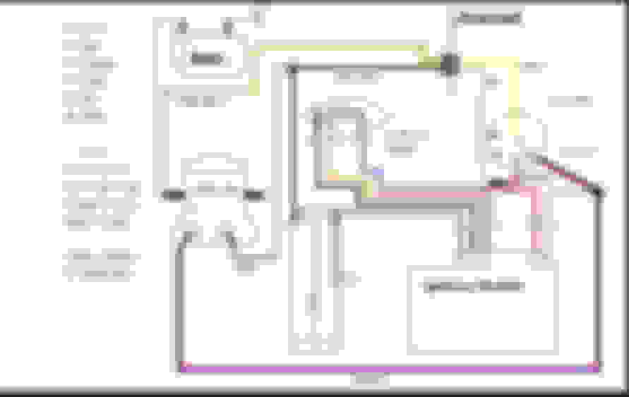


 Always loved those '68-'69 fastbacks!


 Too bad the PO had mechanics replace the original ignition switch tumbler and all - along with the starter and solenoid, while chasing the problem. I fixed it with an $8 starter cable, since O'Reilley's didn't have any flat-braided cable...

