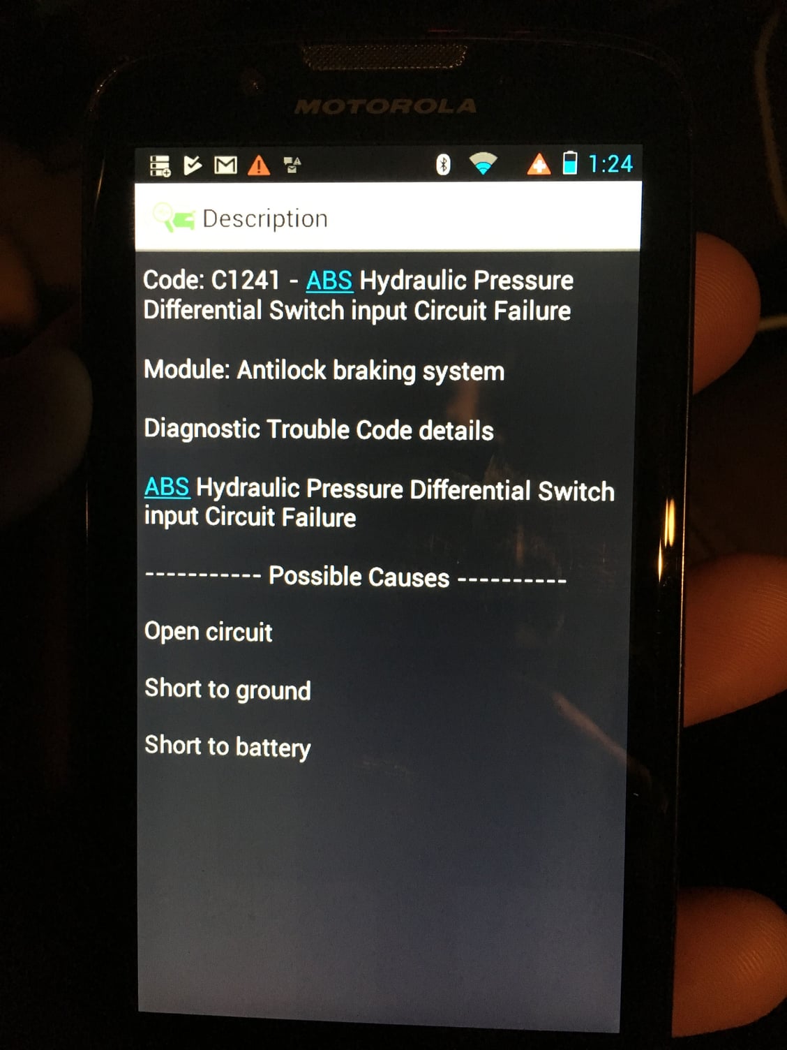
how do I use Forscan to identify my ABS fault
#1
#3
#4
Join Date: Jun 2003
Location: Damon (South East Texas)
Posts: 8,298
Likes: 0
Received 13 Likes
on
12 Posts
PINPOINT TEST J: DTC C1241 — ABS HYDRAULIC PRESSURE DIFFERENTIAL SWITCH INPUT CIRCUIT SHORT TO GROUND
CONDITIONSDETAILS/RESULTS/ACTIONS J1 CHECK THE SWITCH CIRCUIT FOR SHORT TO GROUND
 RABS Valve C1039
  Measure the resistance between RABS valve C1039 pin D, circuit 57 (BK) harness side and ground.
- Is the resistance greater than 10,000 ohms?
 Yes
Yes INSTALL a new anti-lock brake control module. REFER to Module—Anti-Lock Brake Control .
 No
No REPAIR the circuit. CLEAR the DTC. REPEAT the self-test.
Component Test — Intermittent Failures Power/Ground to Anti-Lock Brake Control Module
If the fuse had failed:
- Check the weather packing of the power connector to the anti-lock brake control module C1041.
- Remove power distribution box fuse 14 (60A).
- Measure the resistance between the outside pin of power distribution box fuse 14 (60A), circuit 532 (O/Y), and ground.
- Spray with water and wiggle the wiring between the power distribution box and the anti-lock brake control module.
- If any continuity is measured, repair/replace the wiring.
- Disconnect the anti-lock brake control module C1041.
- While measuring the voltage between anti-lock brake control module C1041-2, circuit 532 (O/Y), and negative battery post, wiggle the wiring harness.
- If the voltage momentary drops below 10 volts, while the harness is wiggled, repair or replace the wiring.
- While measuring the resistance between the anti-lock brake control module C1041-1, circuit 530 (LG/Y), and ground, wiggle the wiring harness.
- If the resistance momentarily goes above 5 ohms, while the harness is wiggled, repair or replace the wiring.
Does not illuminate (prove out):
- Connect EEC-IV 60-Pin Breakout Box to the EHCU with ABS Adapter Cable.
- Connect EEC-IV 60-Pin Breakout Box pin 1 (yellow indicator) to the B+ pin.
- Wiggle the wire harness at the several points between the anti-lock brake control module and the instrument cluster.
- Repair/replace the wire harness at the location that the indicator flickered off for an open circuit.
- Wiggle the wire harness at the several points between the anti-lock brake control module and the instrument cluster.
- Repair/replace the wire harness at the location that the indicator flickered on for a short to ground.
- Connect EEC-IV 60-Pin Breakout Box to the EHCU with ABS Adapter Cable.
- Disconnect the rear anti-lock brake sensor.
- Check the harness for short to ground.
- NOTE: Use 88 Digital Multimeter with the minimum resistance hold feature enabled for this test.Monitor the resistance between EEC-IV 60-Pin Breakout Box pins and ground as follows:SensorBreakout Box PinsCircuitsRear anti-lock brake sensor9 and 21523 (R/PK) and 519 (LG/BK)
- Drive over rough roads at various speeds.
- If there is continuity between either circuit and ground, repair the circuit for a short to ground.
- Check harness for open circuit.
- NOTE: Connect jumper securely to the rear sensor connector.Connect a jumper between the two pins on the rear sensor connector.
- NOTE: Use 88 Digital Multimeter with the maximum resistance hold feature enabled for this test.Monitor the resistance between EEC-IV 60-Pin Breakout Box pins as follows:SensorBreakout Box PinsCircuitsRear anti-lock brake sensor9 and 21523 (R/PK) and 519 (LG/BK)
- Drive over rough roads at various speeds.
- If there is open circuit detected between pins, repair the circuit(s) for an open circuit.
- Check suspect sensor electrical connector.
- NOTE: Use 88 Digital Multimeter with the maximum resistance hold feature enabled for this test.Monitor the resistance between suspect anti-lock brake sensor terminals while wiggling the electrical connector:SensorResistanceRear 4x2 or 4x43,500 ohms
- If the resistance is above specifications, replace the anti-lock brake sensor.
- NOTE: Use 88 Digital Multimeter with the minimum resistance hold feature enabled for this test.Monitor the resistance between rear anti-lock brake sensor terminals while wiggling the electrical connector:SensorResistanceRear 4x2 or 4x4800 ohms
- If the resistance is below specifications, replace the rear anti-lock brake sensor.
- NOTE: Use 88 Digital Multimeter with the minimum resistance hold feature enabled for this test.Monitor the resistance between an anti-lock brake sensor terminal and ground on the highest resistance scale of the meter, while wiggling the electrical connector.
- If the meter shows anything but open circuit, replace the rear anti-lock brake sensor.
Thread
Thread Starter
Forum
Replies
Last Post
z31freakify
1994.5 - 1997 7.3L Power Stroke Diesel
4
08-17-2017 08:46 AM


