When you click on links to various merchants on this site and make a purchase, this can result in this site earning a commission. Affiliate programs and affiliations include, but are not limited to, the eBay Partner Network.
So I decided to do a write up on installation of the 08+ mirrors, wiring up the power fold and power telescoping onto my 2002 Excursion. My goal is to use all factory OEM parts as much as possible. The mirrorsare actually from 2011 which I sourced from two different places. The Driversside mirror has 11 wires and the Passenger side has 16. I did plenty of research and found a great write up on another site that I used for gathering my parts and diagrams.
So I will not go into the detail of installing the mirrors you can get information on this from the following link.>>
Here is my list of parts.
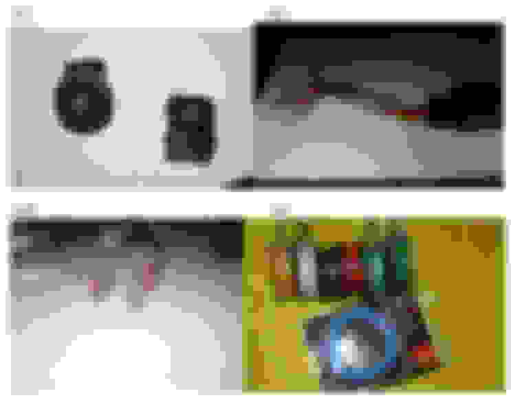
1. Driver and passenger side mirrors - Ebay (Fig1)
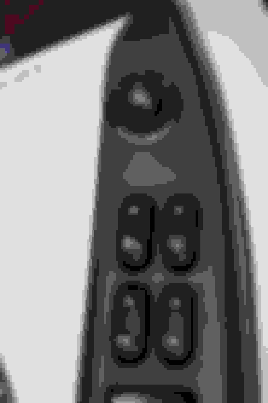
2. 08+ switches for mirror adjustment, power foldand power extend - ebay (Fig2)
3. Relay for power fold � Ford dealership (Fig3)
4. Connector to the relay � AutoZone (Fig3)
5. Female connector to plug into mirror and the terminals - Mouser(Fig4)
6. Male connector to plug into the 08+ mirror switch - Mouser(Fig4)
7. Male connector to plug into the 08+ power telescoping switch - Ford dealership
8. Different color wires - Frys(Fig6)
9. Fuse - AutoZone(Fig7)
10. Mirror caps � A1 auto
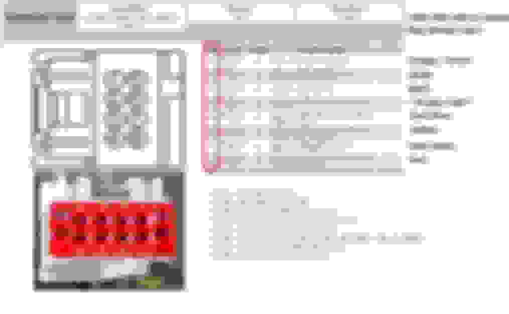
Here is a list of the connectors you can order directly from Mouser that will connect right into the factory harness on the mirrors and the power window switch and the pins for the wires. I was not able to order one for the power telescoping switch as it was out of stock but you can order it from Ford.
Fig -1
Step 1
I installed the mirrors onto my Excursion. These mirrors did not come with the caps so I got the ones that you can color match. I had to get the paint made from a local paint store that was able to put it into a spray can. My color was Aspen Green Metallic and this was not available through the standard automotive stores but the paint store did a good job matching the color.
My Truck now needs to get painted because the mirror paint came out pretty nice.
Step2 .
I created my wiring harness using the different spools of wire. I needed to run 6 wires to the driver�s side and 5 to the passenger side.
2 for power fold
2 for power telescoping
1 for running lights
1 for the switch for power fold (drivers side only)
All other wiring needed was existing in the door panel.
Step 3
Pulled the wire through the factory door boot on both the drivers and passenger sides.
Step 4
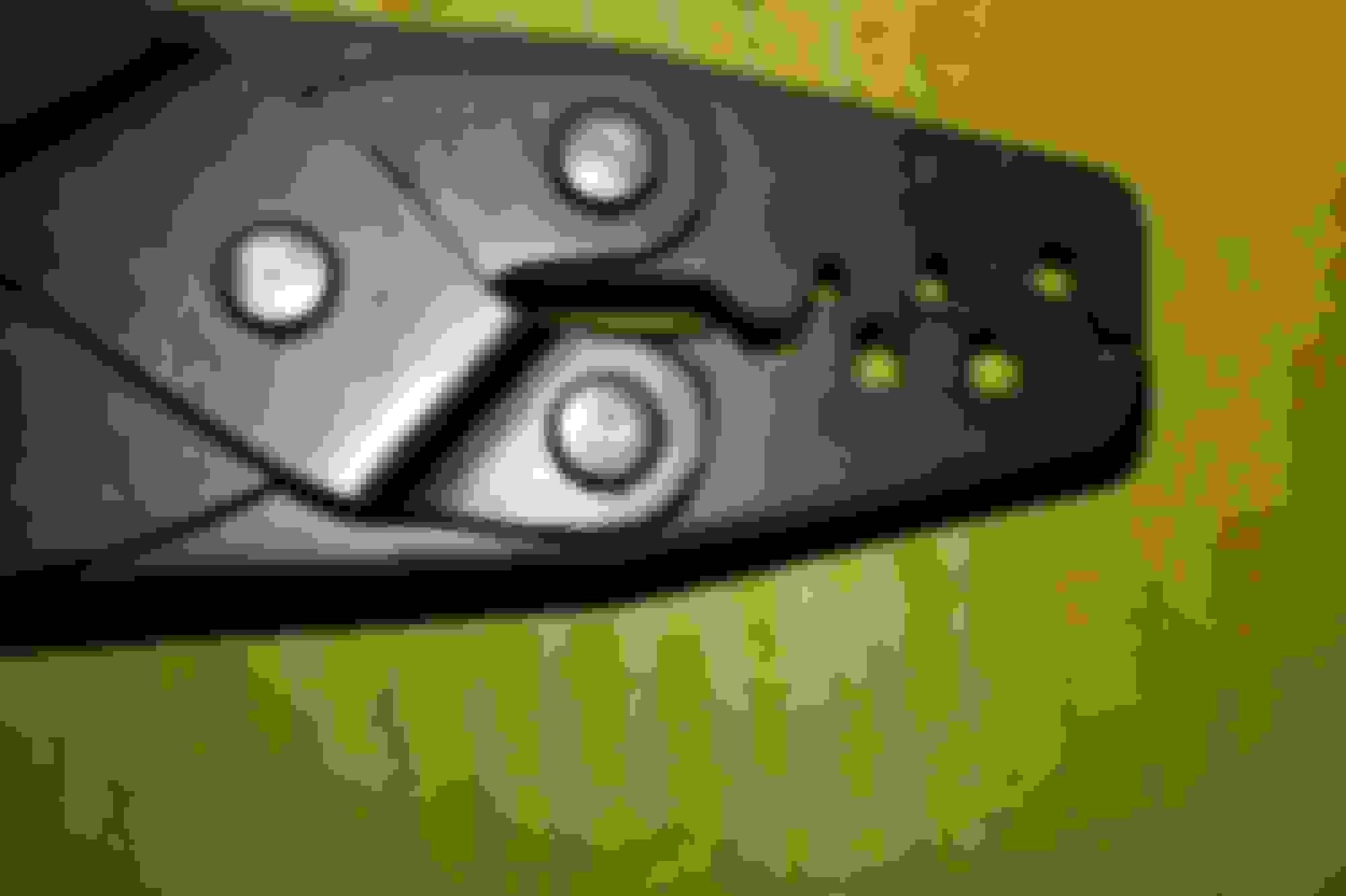
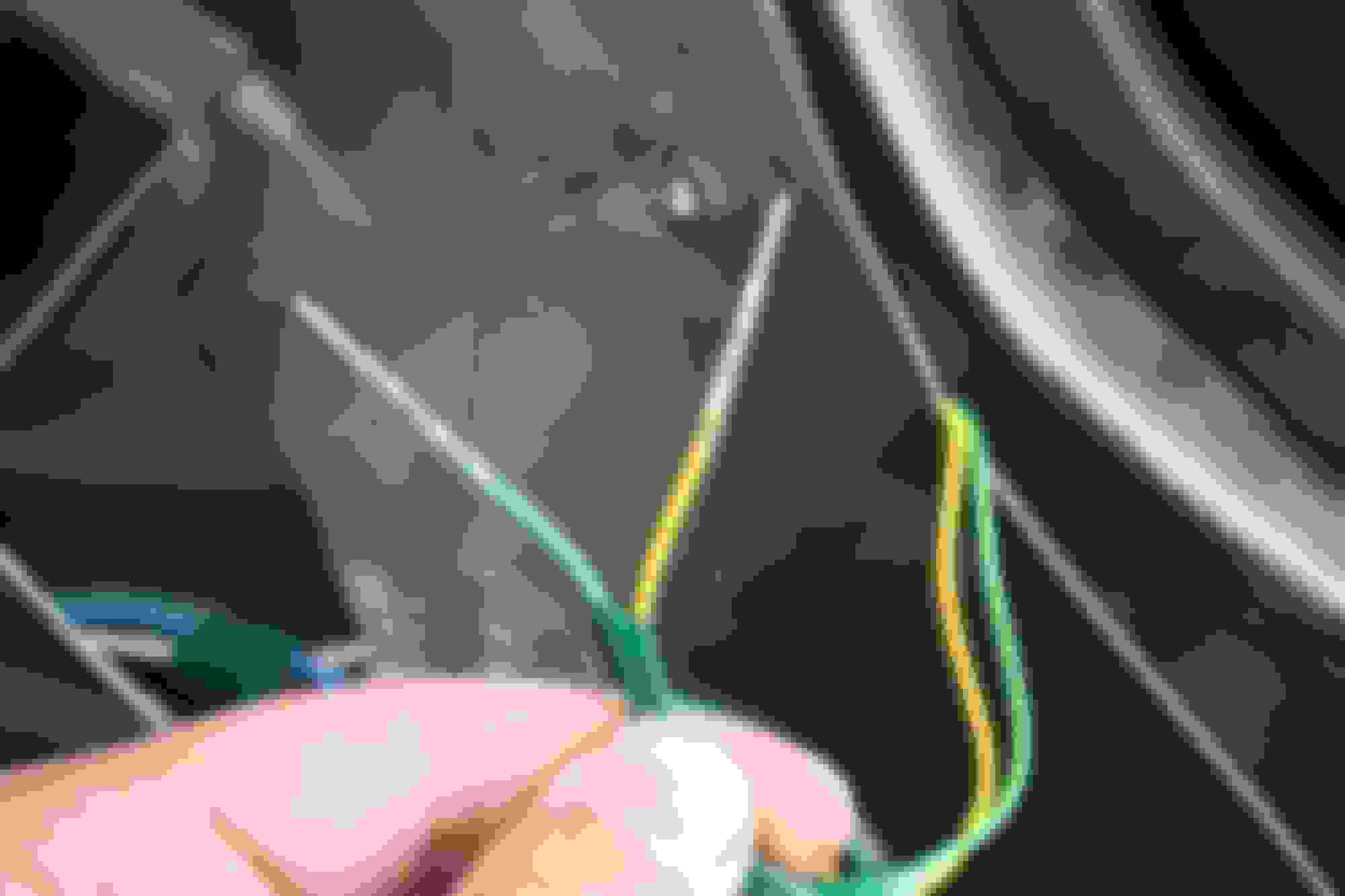
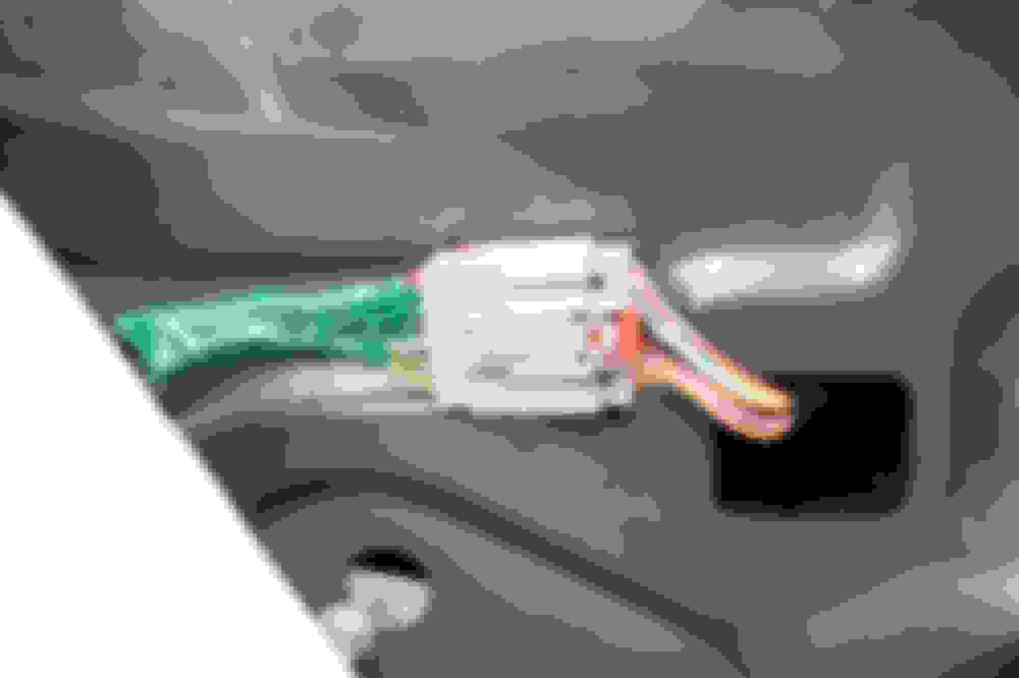
I wired up the connector that plugs directly into the OEM mirror plug. I used connectors and pins from figure 4 above. I crimped the wires using the a nice tool that created the correct hold.
Result of crimping the wire.
After crimping all the wires and putting them into the harness I am now able to connect directly into the wiring harness on the mirror.
I used the following diagrams to wire the connector for the driver�s side. I didn�t really match up the connectors by using the colors except for the existing wires used for the mirror adjustment. The positions listed below matched my mirror harness.
Mouser part #571-2-1419158-5
Pin #1 goes to connector C577 pin #3
Pin #2 goes to Relay position #5
Pin #3 goes to Relay position #2
Pin #4 empty
Pin #5 � Running Lights
Pin #6 - Defrost � existing wire Green/Black
Pin #7 � Ground � black wire
Pin #8 � Turn signal � existing wire light green
Pin #9 goes to connector C527 pin #5 � Dark Blue
Pin #10 goes to connector C527 pin #6 � Yellow
Pin #11 goes to connector C527 pin 8 � Red
Pin #22 goes to connector C577 pin #7
Passenger side. Mouser part #571-2-1419158-5
Pin #1 goes to connector C577 pin #6
Pin #2 goes to Relay position #5
Pin #3 goes to Relay position #2
Pin #4 goes to connector C577 pin #2 � existing wire Purple
Pin #5 � Running Lights
Pin #6 - Defrost � existing wire Green/Black
Pin #7 � Ground � black wire
Pin #8 � Turn signal � existing wire White Blue
Pin #9 goes to connector C527 pin #6 � Yellow
Pin #10 goes to connector C527 pin #7 � Green
Pin #11 goes to connector C527 pin #6 � Yellow � spliced with the yellow in ---Pin #9
Pin #22 goes to connector C577 pin #7
Step 5
I wired up and connected the switch for mirror operation. Using mouser part number 538-30700-1080.
Here is the wiring diagram I used. The colors matched right up from my existing wiring harness (C527).
Mouser part number 538-30700-1080
I had to remove my current mirror adjustment switch and modify the opening for the new 08+ switch. I used the plate that held the new switch to make my template.
I used a rotozip and it sort of got away from me but I won�t show you that picture. But here is the end result and it looks like it was meant to be there.
I had to modify my door panel just a bit to allow control panel with the new mirror switch be allowed to mount properly.
Step 6
Next I wired up the power telescoping switch and mounted the switch. I purchased the following part number from Ford but forgot to take a picture of it. Part #3U2Z-14S411-DAAC � Motorcraft #wpt-1219
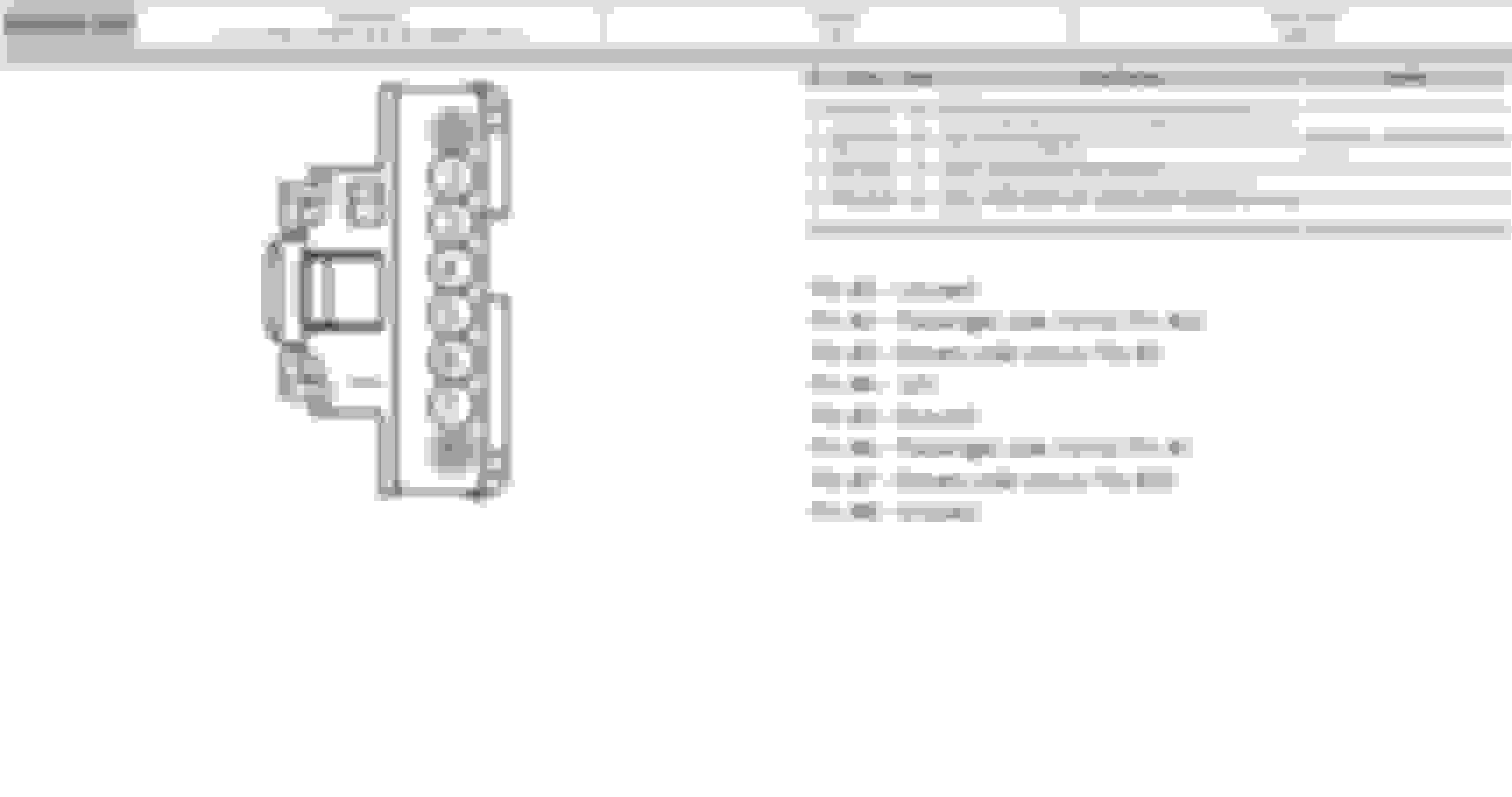
Here is the wiring diagram I used to wire-up the power telescoping switch (C577).
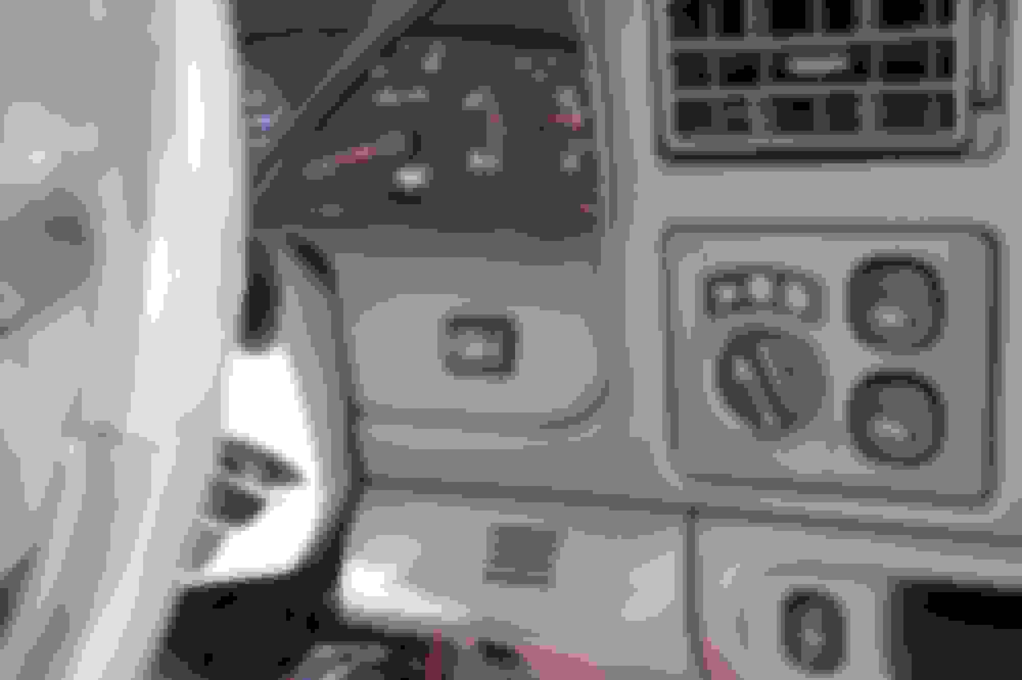
I then needed to decide where to put the switch and I ended up putting it to the right of the steering wheel. I removed the front dash cover so that I could make the opening for the switch.
There is no real way to mount the button so I ended up using epoxy to keep the switch in place. I thought I had a picture of it but I guess I didn�t get it.
Here is the final result.
Step 7
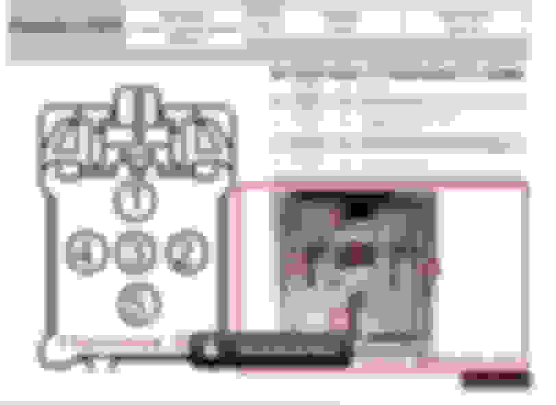
I also wired up the power fold for the mirrors but I am having issues with it and have not completed this part of the setup. I will show the wiring diagram I used to make the connection.
Relay wiring socket for a 5 pin relay. Relay switch Ford OEM part #8C3Z-14N089-A
Here is the wiring diagram used (C3276).
Pin #1 � Ground
Pin #2 � Connected to pin #3 on passenger/drivers mirrors
Pin #3 � 12V fused
Pin #4 � Connected to C527 pin #4
Pin #5 � Connected to pin #2 on passenger/drivers mirrors
What makes the heated mirrors work on these ones? Mine were plug and play, but we are trying to get the running lights, turn signal and the defrost(heated?) mirrors figured out.
My excursion had the following wires already existing:
1. defrost
2. blinker
3. power adjustment
4. ground
5. 12V
Even though my old mirrors didn't have the blinker in them the wire was there for it.
I added the following wiring:
1. Power fold
2. Power Telescoping
3. running lights
When I had my dash out to modify it for my power telescoping I tapped into the running lights wire at the controller next to the steering wheel.
My defrost was already existing and it is connected to a defrost button on the dash.
It is pin #6 on the 22 pin harness on the mirrors for the defrost.
I can't take all credit for the parts but I did do a bunch of reading and research to gather all the information.
There was a thread on another forum which goes into detail on wiring up the mirrors for PF/PT using OEM parts. The thread is 45 pages long which is a bit much.
I took out what I needed from that thread in order to do my mirrors. Some people were able to cut-out the harnesses from a donor truck which would have included the male connector to the mirrors, the female connector for the mirror adjust switch and the female connector for the Power Telescoping and splice the wires together. Since I didn't have access to those, buying the connectors from mouser and wiring them up myself was exactly what I wanted to do.
I was pretty excited to get it looking clean on my truck and since I had a bunch of notes, I figured this site needed a write-up of its own.
My other issue was that many people were using the wire colors to match up to the mirror harness and I couldn't find one that matched my color so matching up the pin# between connectors is what allowed me to be successful.
Great "How-To's" like this are often lost over the years because of bad web links, moved files, deleted accounts, etc. I've managed over the past 8-9 years to snag some of these threads and put them into PDF's which can be easily downloaded by fellow FTE members, and will do so again for this set of instructions. You see, I have a set of '08 take-offs which have the PF/PT functions, so I will certainly need this info later myself.
I'll also admit right up front that I've offered to do this before on some other threads and have not always gotten around to completing the task, but I have some skin in this one myself because of my take-offs which are awaiting an good installation effort (I am a selfish human, after all). It is key that my work load is very light right now. Consequently, this one is going to get completed and posted... perhaps even later today or tomorrow.
At this point, I've already downloaded this entire thread AND the one from Archion on the 08+ Install Upgrade. To reduce the number of pages and file size, I'll clean up the image sizes and delete the extraneously repetitive signatures. I will also potentially delete generic posts which only add to the document length, but only if there is no critical information contained within those posts.
Once the cleanup is complete, I will post the composite PDF for everyone's easy reference and download. I will also include web links to all important details (including the threads), and I will make sure that folks get credit for their inputs. I'm just a facilitator, and want no credit for any of this work.
Great "How-To's" like this are often lost over the years because of bad web links, moved files, deleted accounts, etc. I've managed over the past 8-9 years to snag some of these threads and put them into PDF's which can be easily downloaded by fellow FTE members, and will do so again for this set of instructions. You see, I have a set of '08 take-offs which have the PF/PT functions, so I will certainly need this info later myself.
I will double check but I may have created this in a word document first so that it would make it easier for me to create the post. I can send it to you if you would like to use it and elaborate further.
Having all the information in a new thread will make finding the PDF's much easier years from now so that someone doesn't have to sort through multiple pages of a long thread to find the downloadable files.
I've already posted one PDF for how to make your own wiring adapter harnesses (it was the shortest and easiest to complete), and now this particular thread's How-To is also posted in the thread linked above..
The remaining PDF's will be generated and posted as quickly as I can get them done.

 04-14-2015, 11:43 PM