Bought it! 93 Ranger 4x4! Now we fix.
#1
 01-16-2006, 12:15 PM


Join Date: Dec 2005
Posts: 63
Likes: 0
Received 0 Likes
on
0 Posts
-1993 Ford Ranger XLT
-4.0 A4LD Trans
I had posted a thread a while back, about a truck that I was contemplating on purchasing, because It had a few issues but ended up with it in my driveway!
Soo.. Now I can give some more specifics on the problems I need hammered out.
--4 Wheel drive -- I know, I know, there are tons of these threads floating throughout the forum, but unfortuntely all that I have seen; I don't really follow.
--> So I have no power to the 4x4 Button or the Low Range Button, No lights, grinding, or even clicking. I have went as far as exaiming the 4 Wheel Drive module behind the drivers seat with instrucitons through peiced together threads. I got 4 Flashing pulses from the LED which, rumor has it means power is going to the module and it is NOT defective and the problem is further down the line. Need Help! Unsure what is the next diagonistic step. Callin out the pros once more.
#2
01-16-2006, 11:37 PM
Junior User
Join Date: Sep 2004
Location: Cloverdale, IN
Posts: 66
Likes: 0
Received 0 Likes
on
0 Posts
Control Module Circuits
There are three wiring connectors connected to the electronic control module: the eight-wire pigtail harness connector; the five-wire harness connector; and the eight-wire harness connector.
To check the integrity of these circuits, disconnect the harnesses from the electronic control module and perform the following checks.
Eight-Wire Pigtail Harness Connector
1. Connect a voltmeter between terminal 8 and ground. The voltmeter should indicate battery voltage at all times.
2. Connect a voltmeter between terminal 7 and ground. Then turn the ignition switch to the RUN position. The voltmeter should then indicate battery voltage.
CAUTION:
In the following sections where the usage of an ohmmeter is specified, always remember that an ohmmeter should NEVER be connected into a "live" or powered circuit. If the ohmmeter is subjected to a powered circuit, severe damage will be done to the meter. The vehicle's battery should be disconnected before performing checks on any circuit with an ohmmeter to prevent any accidental damage to the meter.
3. Connect an ohmmeter between terminal 6 and ground. The ohmmeter should indicate a low resistance value (less than 10 ohms).
4. Connect an ohmmeter between terminals 4 and 5 of the wiring harness connector. The ohmmeter should indicate a low resistance value (less than 10 ohms).
5. Connect an ohmmeter between terminal 3 and ground. The ohmmeter should indicate zero ohms.
6. Connect an ohmmeter between terminal 2 and ground. The ohmmeter should indicate zero ohms.

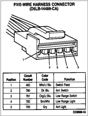
Five-Wire Harness Connector
1. Connect an ohmmeter between terminals 1 and 2. Then depress the 4x4 (2H-4H) switch. The ohmmeter should indicate a low resistance value (less than 50 ohms) while the switch is being depressed.
2. Connect an ohmmeter between terminals 1 and 3. Then depress the LOW RANGE switch. The ohmmeter should indicate a low resistance value (less than 50 ohms) while the switch is being depressed.
3. Connect a test lead between terminal 4 and ground. Turn the ignition switch to RUN and observe the indicator lights. The LOW RANGE light in the instrument panel and LOW RANGE indicator light on the switch should illuminate.
4. Connect a test lead between terminal number five and ground. Turn the ignition switch to RUN and observe the indicator lights. The 4x4 light in the instrument panel and 4x4 light on the switch should illuminate.
Eight-Wire Harness Connector
1. Connect an ohmmeter between terminal 1 and ground. On a vehicle equipped with a manual transmission, depress the clutch pedal and observe the ohmmeter. The ohmmeter should indicate a low resistance (less than 50 ohms) while the clutch pedal is being depressed. If the vehicle is equipped with an automatic transmission, shift the transmission into NEUTRAL and observe the ohmmeter. The ohmmeter should indicate a low resistance (less than 50 ohms) while the transmission selector lever is in the NEUTRAL position.
2. Connect an ohmmeter between terminals 2 and 3. The Ohmmeter should indicate a low resistance reading (225-275 ohms). This will check the continuity of the speed sensor that is located in the transfer case. The speed sensor picks up the rotating speed of the transfer case rear output shaft from two notches that are cut in opposite sides of the outer ring of the clutch housing assembly.

There are three wiring connectors connected to the electronic control module: the eight-wire pigtail harness connector; the five-wire harness connector; and the eight-wire harness connector.
To check the integrity of these circuits, disconnect the harnesses from the electronic control module and perform the following checks.
Eight-Wire Pigtail Harness Connector
1. Connect a voltmeter between terminal 8 and ground. The voltmeter should indicate battery voltage at all times.
2. Connect a voltmeter between terminal 7 and ground. Then turn the ignition switch to the RUN position. The voltmeter should then indicate battery voltage.
CAUTION:
In the following sections where the usage of an ohmmeter is specified, always remember that an ohmmeter should NEVER be connected into a "live" or powered circuit. If the ohmmeter is subjected to a powered circuit, severe damage will be done to the meter. The vehicle's battery should be disconnected before performing checks on any circuit with an ohmmeter to prevent any accidental damage to the meter.
3. Connect an ohmmeter between terminal 6 and ground. The ohmmeter should indicate a low resistance value (less than 10 ohms).
4. Connect an ohmmeter between terminals 4 and 5 of the wiring harness connector. The ohmmeter should indicate a low resistance value (less than 10 ohms).
5. Connect an ohmmeter between terminal 3 and ground. The ohmmeter should indicate zero ohms.
6. Connect an ohmmeter between terminal 2 and ground. The ohmmeter should indicate zero ohms.
Five-Wire Harness Connector
1. Connect an ohmmeter between terminals 1 and 2. Then depress the 4x4 (2H-4H) switch. The ohmmeter should indicate a low resistance value (less than 50 ohms) while the switch is being depressed.
2. Connect an ohmmeter between terminals 1 and 3. Then depress the LOW RANGE switch. The ohmmeter should indicate a low resistance value (less than 50 ohms) while the switch is being depressed.
3. Connect a test lead between terminal 4 and ground. Turn the ignition switch to RUN and observe the indicator lights. The LOW RANGE light in the instrument panel and LOW RANGE indicator light on the switch should illuminate.
4. Connect a test lead between terminal number five and ground. Turn the ignition switch to RUN and observe the indicator lights. The 4x4 light in the instrument panel and 4x4 light on the switch should illuminate.
Eight-Wire Harness Connector
1. Connect an ohmmeter between terminal 1 and ground. On a vehicle equipped with a manual transmission, depress the clutch pedal and observe the ohmmeter. The ohmmeter should indicate a low resistance (less than 50 ohms) while the clutch pedal is being depressed. If the vehicle is equipped with an automatic transmission, shift the transmission into NEUTRAL and observe the ohmmeter. The ohmmeter should indicate a low resistance (less than 50 ohms) while the transmission selector lever is in the NEUTRAL position.
2. Connect an ohmmeter between terminals 2 and 3. The Ohmmeter should indicate a low resistance reading (225-275 ohms). This will check the continuity of the speed sensor that is located in the transfer case. The speed sensor picks up the rotating speed of the transfer case rear output shaft from two notches that are cut in opposite sides of the outer ring of the clutch housing assembly.
Last edited by rangerboy21; 01-16-2006 at 11:54 PM.
#4
01-08-2021, 06:28 PM

#5
01-11-2021, 09:22 AM


Thread
Thread Starter
Forum
Replies
Last Post
hunter.rlh
1987 - 1996 F150 & Larger F-Series Trucks
9
01-10-2020 09:26 AM
ceej4801
1987 - 1996 F150 & Larger F-Series Trucks
18
04-09-2016 10:06 PM
BltFordTough
1983 - 2012 Ranger & B-Series
6
09-30-2008 09:41 PM