When you click on links to various merchants on this site and make a purchase, this can result in this site earning a commission. Affiliate programs and affiliations include, but are not limited to, the eBay Partner Network.
Some progress on the floor… before i move forward i just put the doors in to ensure everything coming together properly and all gaps are set.
First section of the rear of the floor. There will be a lot of pieces that come together for this part, it's a big part of the structure of the floor. Cut it twice and it was still too short! The doors will provide a quick visual check that the floor is fitting together properly when buttoned up
Well... Life managed to get in the way a TON. So i had to put the truck on hold. But I'm back at it!!!!
I went and bought a Carpenter Floor pan and a Direct Sheetmetal 2" recessed firewall to make quick work of finishing up the cab because I want to get onto bigger and better things. Namely... THE FRAME.
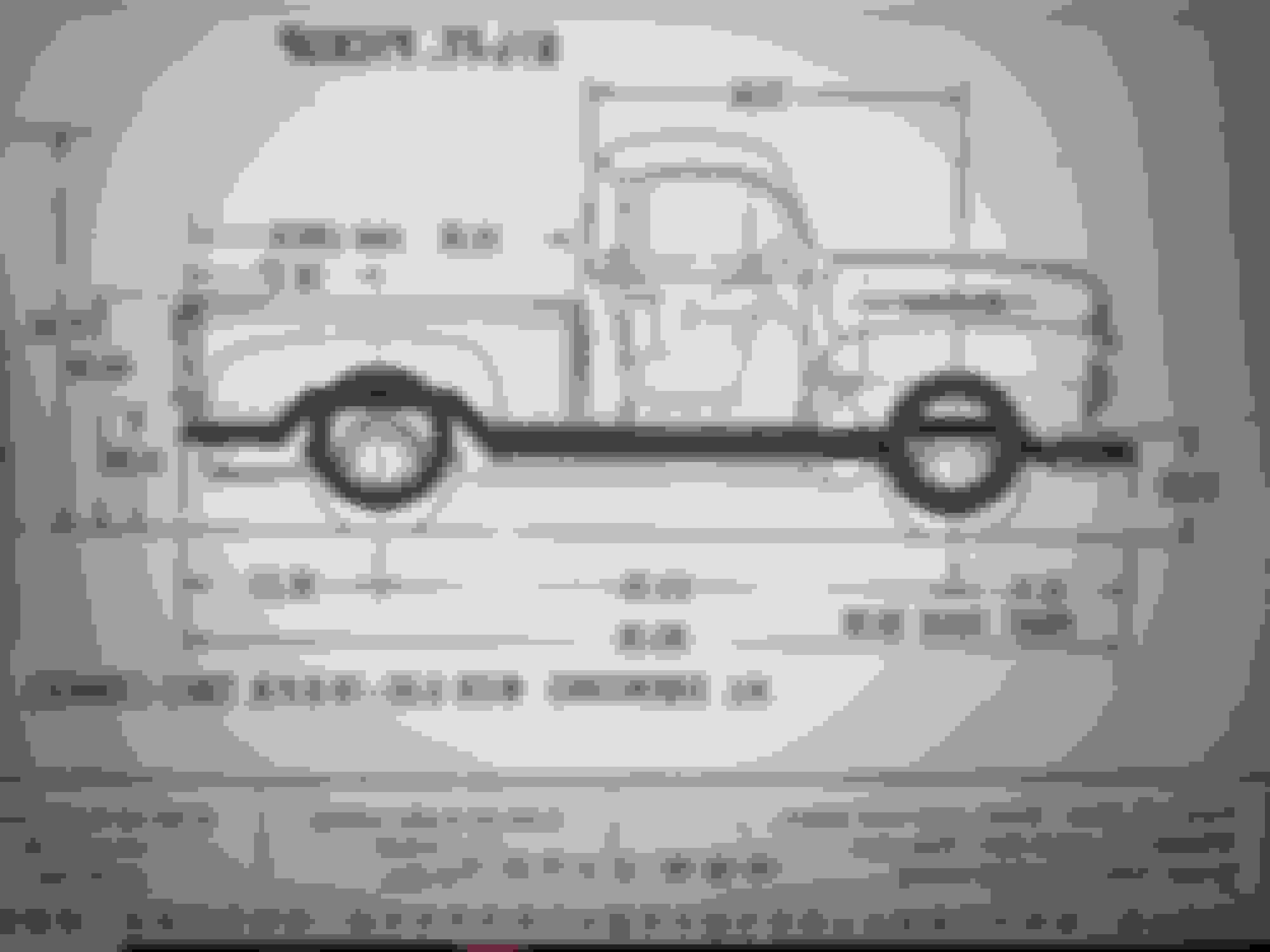
I am beginning to model up the frame build using 2x6 box tubing in the center section and 2x4 on the notches, front and rear. This is a rough rendering but it's a start to get the idea. The ride height is lowered 5" from stock with the stock 28.5" wheel height. I was able to use the factory drawings of the frame and the body with measurements to get the rough dimensions in place. Next I will model up my '89 corvette front suspension in to make sure that (in theory) everything mates up as it should. I am a welder by trade and work in a machine shop next to huge milling machines, lathes and a big water jet. Frame building heaven!!!!
Lately i've had very little time to spend on this project, so i decided to go ahead and buy a floor and a firewall. Finally i got them in and made sure all the door gaps are right where they need to be. just the driver's front corner to replace, the back panel, and the kick panels before i can call this cab good enough and begin on the frame!
I got rid of the kick panels i had previously made... because i hated them. Also, i got rid of the first cab corner i did (driver's front)... because i hated it. i've learned a lot about metal shaping and i can make much better panels in much less time now.
the firewall is a Direct Sheet Metal panel i got from Summit Racing. It was about 1/4" too short in width, so i had to weld in a strip to make it fit properly
The Floor is a Carpenter panel that i got from MWEarlyFords and it was about 95% good. For a perfect restoration i would tweak a few things, but this truck is going to be my do all truck and mostly practical... so i just sent it.
Wanted to share the process i am going through to make the cab body mounts... the original body mounts i made didn't fit as well after i put the new firewall in. Just got them mocked up and will have them waterjet this week and then weld together.
Got both sides of the body mounts mocked up in cardboard and tape
i was able to take the cardboard cutouts, lay them out and take a picture which i brought into fusion, calibrated, and vectorized. i can then export as a .dxf and shoot over to the waterjet
Gov. work is the best! lookin good Travis.
I have a Matsuura 20x30(1987)16,000 pounds, a Lagonamatic, delta control, B.port, 1943 south
bend lathe,16"x6', ,cant weld for chit though.
man, your patch panel work is very nice thanks for sharing.
Greg
Wanted to share the process i am going through to make the cab body mounts... the original body mounts i made didn't fit as well after i put the new firewall in. Just got them mocked up and will have them waterjet this week and then weld together.
Got both sides of the body mounts mocked up in cardboard and tape
i was able to take the cardboard cutouts, lay them out and take a picture which i brought into fusion, calibrated, and vectorized. i can then export as a .dxf and shoot over to the waterjet
Interesting that you use Fusion 3d for this kinda stuff. I use fusion for hard surface video game model type stuff and solidworks for 'hard' realworld type stuff. Though is pretty similar at the end of the day i guess.
Interesting that you use Fusion 3d for this kinda stuff. I use fusion for hard surface video game model type stuff and solidworks for 'hard' realworld type stuff. Though is pretty similar at the end of the day i guess.
I have used fusion and Solidworks. Solid works for machining, and cnc welding at my job, Fusion for projects of mine off the clock. I, personally, prefer Fusion. They basically do the exact same thing, but for assemblies i prefer the fusion interface
Gov. work is the best! lookin good Travis.
I have a Matsuura 20x30(1987)16,000 pounds, a Lagonamatic, delta control, B.port, 1943 south
bend lathe,16"x6', ,cant weld for chit though.
man, your patch panel work is very nice thanks for sharing.
Greg
Thank you, Greg! Much appreciated! At work i use a lot of mori seikis, Haas and hyundai (some with 8 feet of X travel), but for the home shop i've just got a manual bridgeport and the cnc knee mill with a jet 1236p lathe
Not every panel goes smoothly! i had two failed attempts at the pack panel now and i just can't seem to get the result i want, so i will keep moving forward and come back to that at a later date...
i couldn't get the look i wanted out of this back panel. Oh well. i've got the original panel that was riveted onto the back to cover the holes, and for now, i'll put that back on. When the truck is running and i have the patience to make a better one, i will. But for now, i will keep moving forward!
I moved on to this back corner, i have to make the flange for these panels to mate with the floor. just got it tacked in place for now, but i'll finish weld and grind smooth. (Also, yes, my brother dented my freshly replaced corner panel)
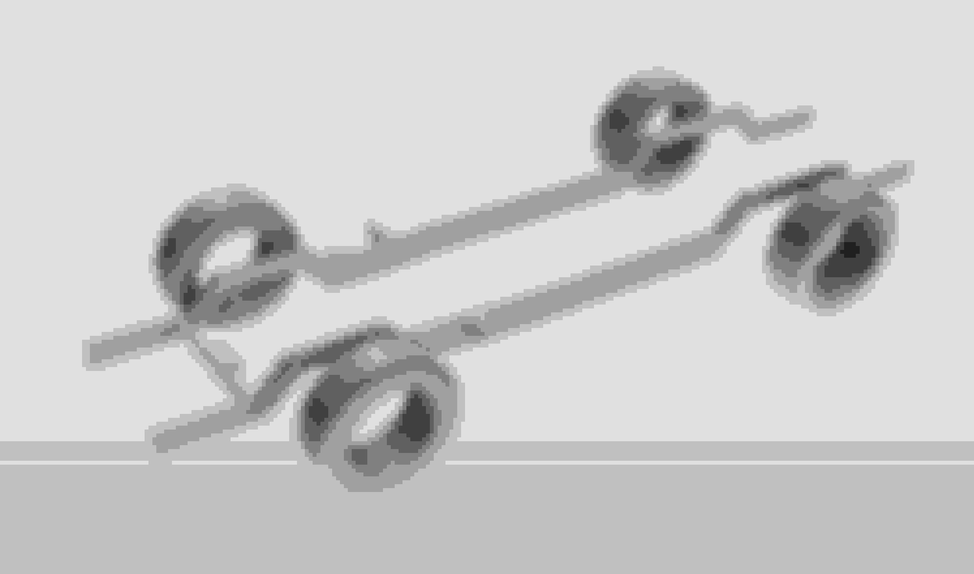
I took the '89 corvette front clip apart and got all the measurements i needed to begin the frame. Made some revisions to the CAD model and i am ready to order the material and begin within the next few weeks...
This is the front clip. I thought, originally, that it required a horizontal frame rail, but the frame rail is actually at 12 deg. facing up toward the front.
This is the most recent rendering of the frame and i THINK the final one before i start to build it...
The final ride height is set for the truck. just 3 or so inches lower than stock. nothing crazy but enough.
 01-22-2019, 09:06 PM


 )
)