Electrical mods
#1
 02-14-2013, 12:20 PM

Electrical mods
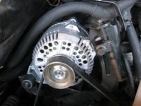
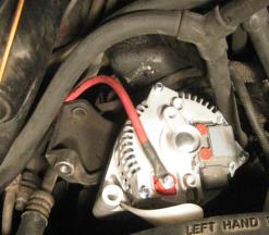
A 3G alternator was installed. This retrofit is applicable to model years thru '91.
Model years from '92 should already have the 3G and perhaps some better wiring.
Check your MY schematics to see if the 4ga cabling is a useful upgrade.
The 95 Amp pivot style was selected for my 3L Vulcan app. Man: WPS, Vendor: RJM
Project motivations were:
* Reduce risk of 2G fire
* Gain amps for additional loads discussed below.
* Periodic replacement of old equipment.
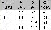
Here is a chart derived from another, larger I found. Note: Even though the 2G was listed as 75A, my '89 schematics lists it as a 60A unit, more consistent with how the 3G's are labeled.
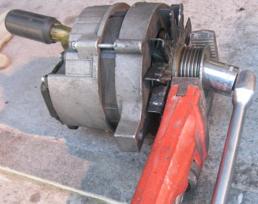
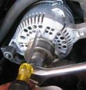
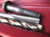
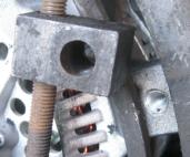
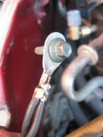
The new 3G ships without a pulley because there are hundreds of applications, so we salvage the pulley guaranteed compatible to our app. Removal of the original pulley was a challenge. Tried 3 methods but the problem was the pulley would rotate on the shaft without the end nut loosening. I'm normally polite but I had to jam a screw driver into its heart while twisting its nut. The pulley required just a small amount of cleanup due to the pipe wrench teeth.
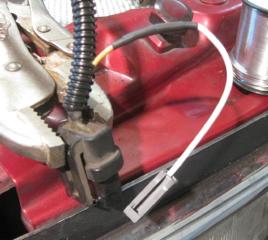
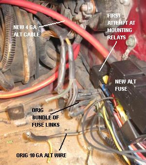
The RJM site provides both the orig 2G schematic and the target 3G schematic. A sensor wire is clipped out of output connector (not shown) and given its own dedicated pigtail from RJM. The black connector is the regulator connector.
A green wire in the regulator harness supports the warning light on the instrument panel, and the yellow wire is used by the internal regulator to sense the output. The original wiring has a yellow output sense wire following the 10 gauge output wire all the way fuse link. We retain this yellow wire and connect it to the 4 gauge cable at the alternator side of the new fuse. By sensing voltage at the battery end of the cable, the alternator can adjust its output to keep a constant voltage at that sensing point, independent of changing current creating changing voltage drop across the cable.
The remaining two (*) 10 gauge wires in the output connector are abandoned and now a 4 gauge cable runs from the alternator to the battery. The higher output of the new alternator can overload the original wiring. Two typical situations where this might happen are 1) when recovering from a depleted battery, and 2) when running high powered audio equipment.
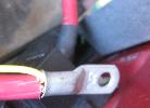
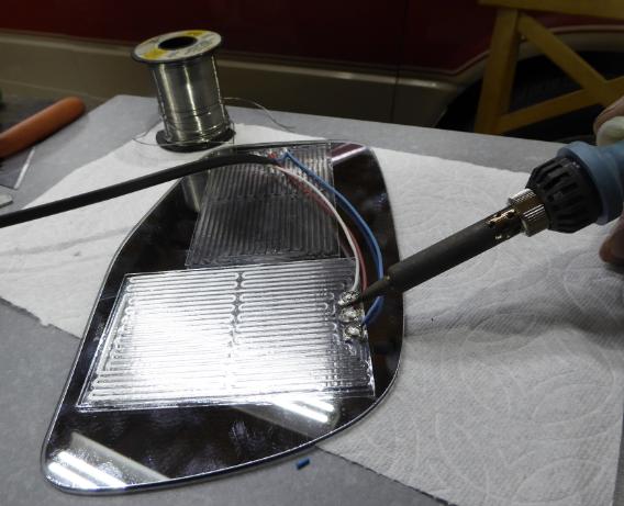
Note: when cutting the cable to length, add slack to anticipate the engine shifting a couple inches on its mounts. The cable is terminated into lugs that are both soldered and crimped.
On pulley install we had the same stator immobilization issue but it was much easier to accomplish. The housing holes provided access and leverage, the internal fan was coupled firmly to the shaft and the entire alternator was bolted down.
The cable routes across the front of the radiator and is tie-wrapped to the original harness.
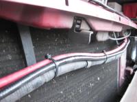
If you follow the original path, it will tuck in behind the upper grill bar.
The alternator from RJM came threaded 5/16 (20 pitch?) along with a too-short too-cheap bolt. My original bolt is 3/8-16x2in (edit: formerly this was mis-identified as an M10-1.5x50mm. Fortunately I double checked before drilling and tapping since the drill size for 3/8 threads is 5/16 while the drill size for M10 threads is 11/32. Also fyi, my 2G had a helicoil. Would be nice.).
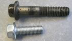
Helicoil on the 2G reman.

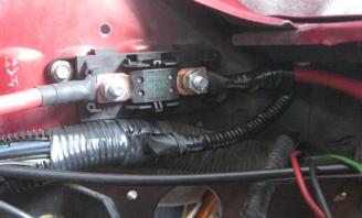
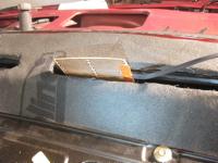
The alternator cable gets a 125 Amp fuse in a dedicated holder bolted to the left fender.
The fuse is set at the battery end of the cable to protect the route to the alternator.
The alternator is naturally limited below the capability of the cable. Fuse and holder brand: Littlefuse. Cover not shown.
I looked at the Bussman brand holder but couldn't figure it out.
At the fuse end of the cable you will be clipping the yellow sensor wire away from the original 10 ga power wire.
You can terminate the yellow wire onto the fuse terminal using a ring, but I decide to combine it into the termination for the 4 ga cable so that they are inseparable.
Therefore no one will someday run the alternator without output sensing.
Note the use of heat shrink and that there are several thicknesses and varieties.
If buying from retail electronics, it's the thin stuff and you should double- or triple-up.
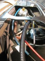
A the cable continues on directly to a gold plated battery terminal.
Coming off the battery terminal is the alternator, the starter with a dedicated 4 gauge cable and another pair of 8 gauge cables for the original electrical components and loads.
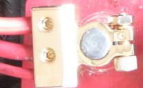
This replaces the original positive battery cable and crusty terminal.
(*)
The voltage drop and temperature rise with the original wiring could be dire because the two 10 gauge wires coming off the 2G actually immediately combine into a single 10 gauge wire that routes the 5 feet to the battery. If I were thinking scientifically, I would have measured the voltage drop, 10 gauge versus 4 gauge. Selecting say a 30 amp load this can also be computed using industry data for wire resistance.
The amount of amps that can be supported with the new cable is highly subjective. It depends on first setting the criteria for voltage drop, allowed temperature gain, ambient temperature, insulation type and safety margins. Here is one guideline I derived from an automotive standards source.
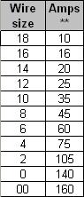
** continuous at 50C.
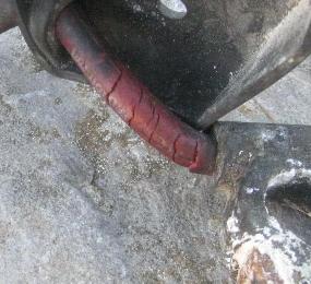
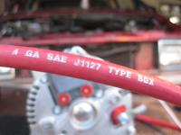
It is also important to select the insulation material. The above pic shows not only that the insulation is extra thick SGX but it is also labeled with the SAE J1127 standard to which it conforms. J1127 supports operation at temps up to 125C. All other wire used in this project is GXL which is also 125C rated but has a thinner covering. Whatever you do, don't use general purpose (GP) hook up wire which you may find in retail. Long before GP gets to its much lower temp rating, it softens considerably and the internal conductor can emerge like hot a knife thru butter, causing cascade failure. At temps far above 125C, I suspect it will char rather than melt.
(more)
Model years from '92 should already have the 3G and perhaps some better wiring.
Check your MY schematics to see if the 4ga cabling is a useful upgrade.
The 95 Amp pivot style was selected for my 3L Vulcan app. Man: WPS, Vendor: RJM
Project motivations were:
* Reduce risk of 2G fire
* Gain amps for additional loads discussed below.
* Periodic replacement of old equipment.
Here is a chart derived from another, larger I found. Note: Even though the 2G was listed as 75A, my '89 schematics lists it as a 60A unit, more consistent with how the 3G's are labeled.
The new 3G ships without a pulley because there are hundreds of applications, so we salvage the pulley guaranteed compatible to our app. Removal of the original pulley was a challenge. Tried 3 methods but the problem was the pulley would rotate on the shaft without the end nut loosening. I'm normally polite but I had to jam a screw driver into its heart while twisting its nut. The pulley required just a small amount of cleanup due to the pipe wrench teeth.
The RJM site provides both the orig 2G schematic and the target 3G schematic. A sensor wire is clipped out of output connector (not shown) and given its own dedicated pigtail from RJM. The black connector is the regulator connector.
A green wire in the regulator harness supports the warning light on the instrument panel, and the yellow wire is used by the internal regulator to sense the output. The original wiring has a yellow output sense wire following the 10 gauge output wire all the way fuse link. We retain this yellow wire and connect it to the 4 gauge cable at the alternator side of the new fuse. By sensing voltage at the battery end of the cable, the alternator can adjust its output to keep a constant voltage at that sensing point, independent of changing current creating changing voltage drop across the cable.
The remaining two (*) 10 gauge wires in the output connector are abandoned and now a 4 gauge cable runs from the alternator to the battery. The higher output of the new alternator can overload the original wiring. Two typical situations where this might happen are 1) when recovering from a depleted battery, and 2) when running high powered audio equipment.
Note: when cutting the cable to length, add slack to anticipate the engine shifting a couple inches on its mounts. The cable is terminated into lugs that are both soldered and crimped.
On pulley install we had the same stator immobilization issue but it was much easier to accomplish. The housing holes provided access and leverage, the internal fan was coupled firmly to the shaft and the entire alternator was bolted down.
The cable routes across the front of the radiator and is tie-wrapped to the original harness.
If you follow the original path, it will tuck in behind the upper grill bar.
The alternator from RJM came threaded 5/16 (20 pitch?) along with a too-short too-cheap bolt. My original bolt is 3/8-16x2in (edit: formerly this was mis-identified as an M10-1.5x50mm. Fortunately I double checked before drilling and tapping since the drill size for 3/8 threads is 5/16 while the drill size for M10 threads is 11/32. Also fyi, my 2G had a helicoil. Would be nice.).
Helicoil on the 2G reman.
The alternator cable gets a 125 Amp fuse in a dedicated holder bolted to the left fender.
The fuse is set at the battery end of the cable to protect the route to the alternator.
The alternator is naturally limited below the capability of the cable. Fuse and holder brand: Littlefuse. Cover not shown.
I looked at the Bussman brand holder but couldn't figure it out.
At the fuse end of the cable you will be clipping the yellow sensor wire away from the original 10 ga power wire.
You can terminate the yellow wire onto the fuse terminal using a ring, but I decide to combine it into the termination for the 4 ga cable so that they are inseparable.
Therefore no one will someday run the alternator without output sensing.
Note the use of heat shrink and that there are several thicknesses and varieties.
If buying from retail electronics, it's the thin stuff and you should double- or triple-up.
A the cable continues on directly to a gold plated battery terminal.
Coming off the battery terminal is the alternator, the starter with a dedicated 4 gauge cable and another pair of 8 gauge cables for the original electrical components and loads.
This replaces the original positive battery cable and crusty terminal.
(*)
The voltage drop and temperature rise with the original wiring could be dire because the two 10 gauge wires coming off the 2G actually immediately combine into a single 10 gauge wire that routes the 5 feet to the battery. If I were thinking scientifically, I would have measured the voltage drop, 10 gauge versus 4 gauge. Selecting say a 30 amp load this can also be computed using industry data for wire resistance.
The amount of amps that can be supported with the new cable is highly subjective. It depends on first setting the criteria for voltage drop, allowed temperature gain, ambient temperature, insulation type and safety margins. Here is one guideline I derived from an automotive standards source.
** continuous at 50C.
It is also important to select the insulation material. The above pic shows not only that the insulation is extra thick SGX but it is also labeled with the SAE J1127 standard to which it conforms. J1127 supports operation at temps up to 125C. All other wire used in this project is GXL which is also 125C rated but has a thinner covering. Whatever you do, don't use general purpose (GP) hook up wire which you may find in retail. Long before GP gets to its much lower temp rating, it softens considerably and the internal conductor can emerge like hot a knife thru butter, causing cascade failure. At temps far above 125C, I suspect it will char rather than melt.
(more)
Last edited by RojoStar; 05-02-2018 at 10:00 AM. Reason: PB pic link repair
#2
02-14-2013, 12:23 PM
Fuse box
At the far end of the alternator's output wire, the sensor wire is retrieved from where if finally connects in with the single 10 gauge at the fuse link.
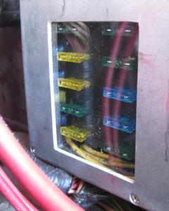
This is when I unexpectedly decided that this mess of fuse links was also archaic and should be sorted out.
I can't imagine what I would do out in the middle of no where and I melt a fuse link (possibly causing cascade failure) rather than blow a standard replaceable fuse.
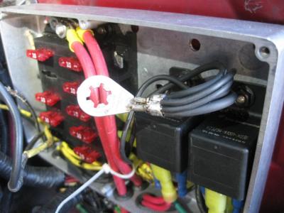
So we design, build and install an honest fuse panel in place of the fuse links. Note: that there is an original subpanel inside the van.
A benefit to retrofitting a fuse panel is that I can then install and protect additional circuits.
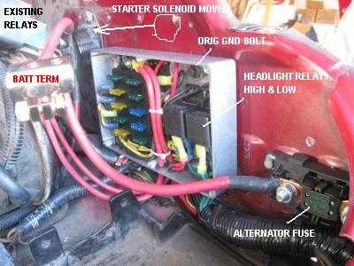
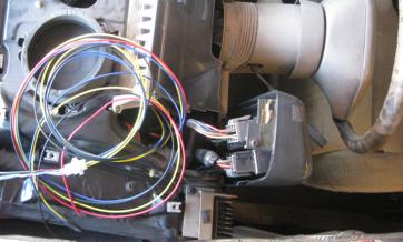
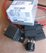
For instance, suitably sized fuse box also provides room to fuse and shelter headlight relays, shown here.
To make room for my box, the starter relay needs to be shifted rearward.
This particular fuse block is rated at 30 amps per tap, 160 amps total.
It is fed by two 8 gauge cables from the battery terminal safely providing at least 80 amps.
Battery and covers for the fuse box and alternator fuse are removed for this pic.
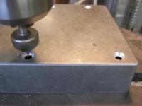
Drill and countersink for fuse block and relay mounting screws.
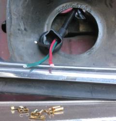
My box overlays the original ground point for the left headlight.
Since the relay control circuit inside the box had to reach ground somehow anyway, original ground wires were brought into the box and everyone met up at the original lug using the original bolt punching thru to the original thread hole in the fender.
The circuit that was originally feeding the headlights, now turns on a couple relays with are fed directly from the new fuse panel.
The advantage to this is it diverts the 10 amps or so away from the headlight switch, reduces the path length from power to load and allows you to retrofit what ever size wire you want.
The headlights were originally driven using 16 gauge wire.
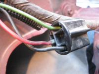
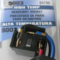
To reduce voltage drop from the relay, 12 gauge wire is retrofitted. A Dorman 9003 sealed-beam connector provided a housing, contacts and boot.
Although it also cam with a short length of wire and conduit, I used my own full length wire without the need for splices or butt connections.
My color-correct GXL wires were solder to the Dorman terminals. Note: housing not shown in 2nd pic.
Headlight ground wires were upgraded from 16 gauge to 12 gauge, both fenders.
Wires to the right headlight were placed in conduit, then wrapped with electrical tape and routed along the same path as the new alternator cable and the original harness.

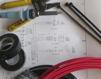
********* Tools **********
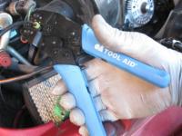
If you're gonna get serious about automotive wiring, you need to splurge on a crimper.
This is when I unexpectedly decided that this mess of fuse links was also archaic and should be sorted out.
I can't imagine what I would do out in the middle of no where and I melt a fuse link (possibly causing cascade failure) rather than blow a standard replaceable fuse.
So we design, build and install an honest fuse panel in place of the fuse links. Note: that there is an original subpanel inside the van.
A benefit to retrofitting a fuse panel is that I can then install and protect additional circuits.
For instance, suitably sized fuse box also provides room to fuse and shelter headlight relays, shown here.
To make room for my box, the starter relay needs to be shifted rearward.
This particular fuse block is rated at 30 amps per tap, 160 amps total.
It is fed by two 8 gauge cables from the battery terminal safely providing at least 80 amps.
Battery and covers for the fuse box and alternator fuse are removed for this pic.
Drill and countersink for fuse block and relay mounting screws.
My box overlays the original ground point for the left headlight.
Since the relay control circuit inside the box had to reach ground somehow anyway, original ground wires were brought into the box and everyone met up at the original lug using the original bolt punching thru to the original thread hole in the fender.
The circuit that was originally feeding the headlights, now turns on a couple relays with are fed directly from the new fuse panel.
The advantage to this is it diverts the 10 amps or so away from the headlight switch, reduces the path length from power to load and allows you to retrofit what ever size wire you want.
The headlights were originally driven using 16 gauge wire.
To reduce voltage drop from the relay, 12 gauge wire is retrofitted. A Dorman 9003 sealed-beam connector provided a housing, contacts and boot.
Although it also cam with a short length of wire and conduit, I used my own full length wire without the need for splices or butt connections.
My color-correct GXL wires were solder to the Dorman terminals. Note: housing not shown in 2nd pic.
Headlight ground wires were upgraded from 16 gauge to 12 gauge, both fenders.
Wires to the right headlight were placed in conduit, then wrapped with electrical tape and routed along the same path as the new alternator cable and the original harness.
********* Tools **********
If you're gonna get serious about automotive wiring, you need to splurge on a crimper.
Last edited by RojoStar; 05-02-2018 at 10:30 AM. Reason: PB pic link repair
#3
02-14-2013, 12:25 PM
Heating pads
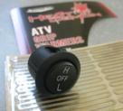
My van has the powered style side mirrors. The mirrors were retrofitted with heater pads that typically marketed for use as hand warmers on motorcycles.
Each pad puts out 15 watts on low and perhaps 25 watts on high. Along with wires and connectors, each heater pad kit contains two pads and one rocker switch.
The switch selects between off, high and low power.
Product: Symtec Grip Warmers, Kit for ATVs, model 210007. Other brands will probably work also, but you're on your own.
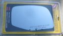
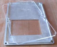
I had no advanced knowledge of how to get at the backside of the mirrors, but after a little messing around, the logical conclusion was that the mirror glass is glued to the subframe.
I then instantly destroyed the glass by just slightly prying in exactly the wrong place, along the long edge.
Forewarned, I then applied a windshield knife to the other side, but ironic luck would have it that it was ready to fall off anyway, so I can't say whether the method works.

Right-hand glass: Dorman 51275, $20.
The housing needs to be dissembled from the base in order to route wires. I finally discovered a thin enough star drive to get into one of the wells.
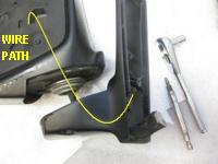
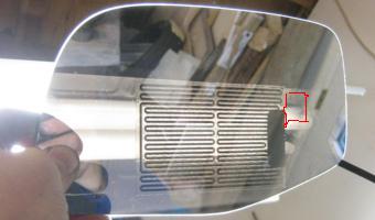
The pad is attached by peel-and-stick to the back side of the glass, although viewed here thru the glass from the front. On my first attempt I set the pad low thinking heat rises, which it does.
However, its more important to line up the wire connection with the routing hole in the housing (approx by red markup) so that the wire thickness is not a factor.
Too late. I'll get it right on the other (new) mirror.
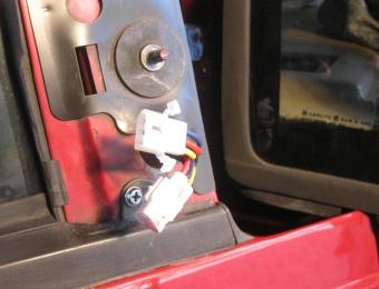
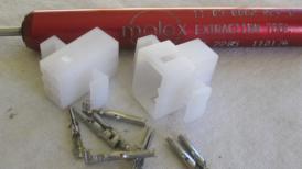
At the sheetmetal, a heater connector is retrofitted along side the original one for directional control. Product: Molex .062 series, 3 position, model 1625-3PRT.
Note: a Molex compatible extractor tool is required if you make a mistake.
An alternative approach is to merge the old positioning circuits and the new heater circuits into one 6-pin molex connector.
Meanwhile, other pads are dropped into the ducts feeding the windshield. This is easily done while the windshield is removed for an entirely different reason (it was leaking).
Note: Dynaliner has also been applied to the dash internal metal in order to knock down engine noise.
Circuits for both the mirror and the windshield are placed into a conduit and routed across the dash.
All heater pad circuits combine in the left side of the instrument pod. Here the output of the timed switch originally driving the rear window defrost, instead is used to control a new relay fed from our new fuse panel.
The new relay feeds pads in the two mirrors, 3 in the front duct plus the rear defrost.
Mounting the relay switch and fuses into a box allows you to do many of the connections on the workbench, then drop the completed box into position.
Requires molex connectors (not shown) for the new harness.
Using 3 kits one rocker switch was buried in each door, and one switch was mounted along side the new relay inside the instrument pod.
You could make the switches more accessible if you like. I'll start off configured for low power, and will report back only if that is not sufficient.
*** update, 2017 ***
After an evaluation period of several years, I got sufficiently annoyed with the small coverage that I converted to two pads per mirror, electrically connected in parallel.
The orientation of the pads is to give good up-down coverage nearest the body, then stretch the other one out to the outside for best peripheral coverage (into the next lanes, beside and behind).
Also, I was never happy with the heater pads in the ducts.
Always smelled like it was overheating the plastic, so I took it off line immediately, never used it again.
Instead the current plan is to install an aux heater pump into the coolant lines to circulate engine heat to the heater core, even before the thermostat allows for it.
Each pad puts out 15 watts on low and perhaps 25 watts on high. Along with wires and connectors, each heater pad kit contains two pads and one rocker switch.
The switch selects between off, high and low power.
Product: Symtec Grip Warmers, Kit for ATVs, model 210007. Other brands will probably work also, but you're on your own.
I had no advanced knowledge of how to get at the backside of the mirrors, but after a little messing around, the logical conclusion was that the mirror glass is glued to the subframe.
I then instantly destroyed the glass by just slightly prying in exactly the wrong place, along the long edge.
Forewarned, I then applied a windshield knife to the other side, but ironic luck would have it that it was ready to fall off anyway, so I can't say whether the method works.
Right-hand glass: Dorman 51275, $20.
The housing needs to be dissembled from the base in order to route wires. I finally discovered a thin enough star drive to get into one of the wells.
The pad is attached by peel-and-stick to the back side of the glass, although viewed here thru the glass from the front. On my first attempt I set the pad low thinking heat rises, which it does.
However, its more important to line up the wire connection with the routing hole in the housing (approx by red markup) so that the wire thickness is not a factor.
Too late. I'll get it right on the other (new) mirror.
At the sheetmetal, a heater connector is retrofitted along side the original one for directional control. Product: Molex .062 series, 3 position, model 1625-3PRT.
Note: a Molex compatible extractor tool is required if you make a mistake.
An alternative approach is to merge the old positioning circuits and the new heater circuits into one 6-pin molex connector.
Meanwhile, other pads are dropped into the ducts feeding the windshield. This is easily done while the windshield is removed for an entirely different reason (it was leaking).
Note: Dynaliner has also been applied to the dash internal metal in order to knock down engine noise.
Circuits for both the mirror and the windshield are placed into a conduit and routed across the dash.
All heater pad circuits combine in the left side of the instrument pod. Here the output of the timed switch originally driving the rear window defrost, instead is used to control a new relay fed from our new fuse panel.
The new relay feeds pads in the two mirrors, 3 in the front duct plus the rear defrost.
Mounting the relay switch and fuses into a box allows you to do many of the connections on the workbench, then drop the completed box into position.
Requires molex connectors (not shown) for the new harness.
Using 3 kits one rocker switch was buried in each door, and one switch was mounted along side the new relay inside the instrument pod.
You could make the switches more accessible if you like. I'll start off configured for low power, and will report back only if that is not sufficient.
*** update, 2017 ***
After an evaluation period of several years, I got sufficiently annoyed with the small coverage that I converted to two pads per mirror, electrically connected in parallel.
The orientation of the pads is to give good up-down coverage nearest the body, then stretch the other one out to the outside for best peripheral coverage (into the next lanes, beside and behind).
Also, I was never happy with the heater pads in the ducts.
Always smelled like it was overheating the plastic, so I took it off line immediately, never used it again.
Instead the current plan is to install an aux heater pump into the coolant lines to circulate engine heat to the heater core, even before the thermostat allows for it.
Last edited by RojoStar; 05-02-2018 at 11:12 AM. Reason: PB pic link repair
#4
02-14-2013, 12:29 PM
Futures
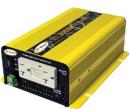
A dedicated 8-gauge cable comes off the battery to feed a 300-watt 120V pure inverter mounted into the 3rd row stash holes.
The same cable splits off into fused 10-gauge wire for the front and rear cigarette lighters.
* Summer/Fall 2013 or whenever I finish up.
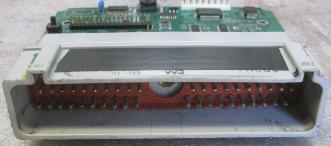
A custom EEC-IV gets swapped in. Adds knock, wbo2, obd, usb. Don't ask.
* When ever
There is a negative battery terminal.

* When ever
Remote keyless entry.
Fast forward, June 2017. See post 13, this thread.
* Summer 2013
Interior lighting.
The same cable splits off into fused 10-gauge wire for the front and rear cigarette lighters.
* Summer/Fall 2013 or whenever I finish up.
A custom EEC-IV gets swapped in. Adds knock, wbo2, obd, usb. Don't ask.
* When ever
There is a negative battery terminal.
* When ever
Remote keyless entry.
Fast forward, June 2017. See post 13, this thread.
* Summer 2013
Interior lighting.
Last edited by RojoStar; 05-02-2018 at 11:48 AM. Reason: PB pic link repair
#5
02-14-2013, 01:54 PM
#6
02-14-2013, 02:28 PM
Thank you.
That's a Sierra International FS40740 fuse block sitting in a Hammond box, size DD.
The box is very tight and I'm going to have to line the lid to prevent contact with open top fuses.
Or do a plexiglass lid. You can find my product review (of the fuse block) on Amazon along with an alternate, prettier picture of the box.
Last edited by RojoStar; 05-02-2018 at 11:34 AM. Reason: PB pic link repair
#7
04-27-2013, 05:06 PM
Window motor
I was worried about the new fuse box, but it has worked so far.
Btw, that plexiglass had to be cut in half so it only covered the fuse window portion, because the standard bosch relays were a bit too tall to fit along with the thickness of the plexi.
*****************
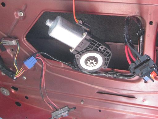
The passenger side window motor has always struggled to operate. It's a chronic problem that has had me swapping out motors more than twice.
This time I bought a premium brand, but still the same result. Tried silicon spray, etc.
Since the switch on the passenger door seemed to operate the motor noticeably better than the switch on the driver door, I concluded that there was too much voltage drop across a too thin wire.
So using 12 gauge wire instead of the original 14ga, I rebuilt both the passenger door harness and the driver door harness (but not yet the harness between the left and right side of the van).
Suddenly the motors could quite easily move the glass, and scary fast.
This seemed strange to me since the door harnesses were too short to either contribute so much to a problem or the solution.
So here is what I think actually happened...
During the wire swap I moved all the connector terminals from the old wire to new wire and changed the connection method from crimped to soldered.
I now believe that oxidation had for some time invaded the crimped connections, coated the wire strands and caused the loss of power.
When I removed the switches and soldered the connector terminals it removed all the oxidation allowing full power to flow.
Probably would have worked using the original 14ga wires.
Btw, if you do any troubleshooting, get the factory schematics. For example the 1989 model year uses fps-12135-89H. 14 pages, 17x27 inches original.
Btw, that plexiglass had to be cut in half so it only covered the fuse window portion, because the standard bosch relays were a bit too tall to fit along with the thickness of the plexi.
*****************
The passenger side window motor has always struggled to operate. It's a chronic problem that has had me swapping out motors more than twice.
This time I bought a premium brand, but still the same result. Tried silicon spray, etc.
Since the switch on the passenger door seemed to operate the motor noticeably better than the switch on the driver door, I concluded that there was too much voltage drop across a too thin wire.
So using 12 gauge wire instead of the original 14ga, I rebuilt both the passenger door harness and the driver door harness (but not yet the harness between the left and right side of the van).
Suddenly the motors could quite easily move the glass, and scary fast.
This seemed strange to me since the door harnesses were too short to either contribute so much to a problem or the solution.
So here is what I think actually happened...
During the wire swap I moved all the connector terminals from the old wire to new wire and changed the connection method from crimped to soldered.
I now believe that oxidation had for some time invaded the crimped connections, coated the wire strands and caused the loss of power.
When I removed the switches and soldered the connector terminals it removed all the oxidation allowing full power to flow.
Probably would have worked using the original 14ga wires.
Btw, if you do any troubleshooting, get the factory schematics. For example the 1989 model year uses fps-12135-89H. 14 pages, 17x27 inches original.
Last edited by RojoStar; 05-02-2018 at 11:59 AM. Reason: PB pic link repair
Trending Topics
#8
04-27-2013, 10:33 PM

The new 3G ships without a pulley because there are hundreds of applications, so we salvage the pulley guaranteed compatible to our app. Removal of the original pulley was a challenge. Tried 3 methods but the problem was the pulley would rotate on the shaft without the end nut loosening.

#9
04-28-2013, 03:27 AM
like the idea of gauge upgrade on the window lift motor wiring.
I've had to replace much of the engine compartment and rear lights wiring in my Aero over the years due to corrosion issues with the poor insulation bare copper wire Ford used. at least it's a high copper percentage wire with max current carry capabilities and not that cheap pot metal low copper replacement spool garbage sold in the auto parts stores.
I only use US made tinned stranded copper replacement wire rated for marine apps carrying the US Coast Guard Electrical Regulations 33 CFR and the ABYC certifications
no corrosion problems and never had an insulation wear/rub thru.
All connections soldered after crimp followed with heat shrink tubing.
http://gregsmarinewiresupply.com/Zen/
All my batt cables are oversized tinned marine copper with HD crimped and silver soldered lugs. Even did this on my Dodge Ram Cummins. Fast cold crank starts even at 0d F and below. Oversized the alt. cable also
I only use my Aero 4L for intown suburban and logging gravel road trips seldom up to freeway speed for any distance so I went to an undersize higher rpm pulley wheel on my 3G 130 amp upgrade alt. run a large AC converter on 2 large deep cycles for my camera, video, computer and mudding creek crawler events
hate the Jap cars for their cheap Chinese made low quality wiring, the repair shops rip my wife off every wiring problem.
Learned the hard way from my ocean small craft boating days. fisherman lives and dies by his wiring.
I fish on and across the Columbia River bar out 50 miles
<iframe width="420" height="315" src="http://www.youtube.com/embed/O_Ot9A-8Qm0" frameborder="0" allowfullscreen></iframe>
#10
04-28-2013, 09:08 AM
Haven't tried. The problem is slippage of the fan & pulley, not how tight the nut is. An impact wrench might work due to the sudden torque against the mass inertia of the stator. Good suggestion. I should add impact wrench to my tool collection.
This confirms a concern, that I will have to rewire the rear harness for towing. I'll put it on the list.
Great link to the tinned wire supply. I'm using automotive rated bare copper from wireandsupply.com. But from now on, I'm tinning the ends before crimping.
Great link to the tinned wire supply. I'm using automotive rated bare copper from wireandsupply.com. But from now on, I'm tinning the ends before crimping.
#11
04-28-2013, 09:42 AM
I use them all the time to take off pulleys or the cooling fins on an alternator. Put a leather glove on one hand to hold the fins and the pulley. Hold the impact with your other hand and it zips them right off. Works like a charm to install them too, just don't overdo it. Use an old, throwaway alternator for practice.
#12
12-06-2013, 10:18 AM
Project: Fuse subpanel added.
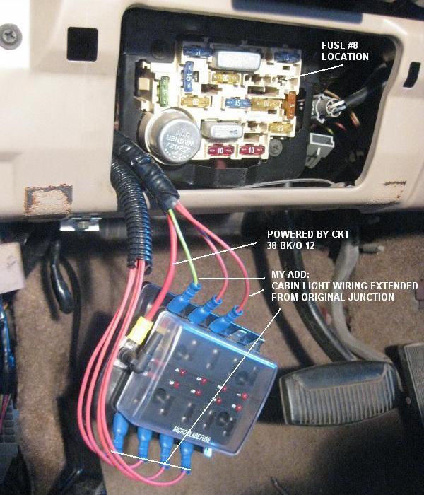
Problem: Some intermittent fault was killing fuse #8 on the main panel, taking down the speedometer and the overhead trip computer.
*****
I went into the factory schematics and, as usual, didn't like what I saw.
Fuse #8 supplies basically the entire world of courtesy lights inside the van, plus the outside mirrors. Then someone decided to put the high priority speedometer onto the same circuit.
The reason was (probably) that the speedo and trip computer required "always on" power which is what fuse 8 provides.
Up until two days ago I had the speedo rerouted to use only fuse #17 (a switched circuit that redundantly goes to the speedo and trip computer) to get it off the faulted circuit.
But the trip computer was still on the faulted cabin light circuit causing, amongst other things, the fuel level sensor to not to read correctly.
***** Fuse 8 original loads ***
- Cargo lamp
- Clock
- Courtesy lamp
- Dome lamp
- Instrument cluster
- Glove box lamp
- Illuminated entry (??)
- Instrument panel courtesy lamps
- Power mirrors
- Trip computer
- Reading lamps
- Rear antilock brake system
- Stepwell lamp
- Visor vanity lamps
***** My Mods ****
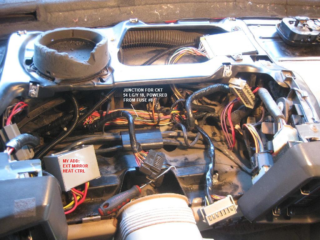
The cabin lights were fished out of the harness behind the instrument cluster and routed back to a new sub panel.
This sub panel is then fed directly from the same cable that supplies fuse 8.
Each of the loads on the cabin lamp circuit now get their own new fuse, thus isolating any fault and greatly aiding in finding the intermittent.
The higher priority speedo and trip computer were placed back onto fuse 8 and are now the the only loads on that circuit.
A future project would be to put the new sub panel onto a timer, rather than being "always on" possibly depleting the battery when a reading lamp is left on.
Problem: Some intermittent fault was killing fuse #8 on the main panel, taking down the speedometer and the overhead trip computer.
*****
I went into the factory schematics and, as usual, didn't like what I saw.
Fuse #8 supplies basically the entire world of courtesy lights inside the van, plus the outside mirrors. Then someone decided to put the high priority speedometer onto the same circuit.
The reason was (probably) that the speedo and trip computer required "always on" power which is what fuse 8 provides.
Up until two days ago I had the speedo rerouted to use only fuse #17 (a switched circuit that redundantly goes to the speedo and trip computer) to get it off the faulted circuit.
But the trip computer was still on the faulted cabin light circuit causing, amongst other things, the fuel level sensor to not to read correctly.
***** Fuse 8 original loads ***
- Cargo lamp
- Clock
- Courtesy lamp
- Dome lamp
- Instrument cluster
- Glove box lamp
- Illuminated entry (??)
- Instrument panel courtesy lamps
- Power mirrors
- Trip computer
- Reading lamps
- Rear antilock brake system
- Stepwell lamp
- Visor vanity lamps
***** My Mods ****
The cabin lights were fished out of the harness behind the instrument cluster and routed back to a new sub panel.
This sub panel is then fed directly from the same cable that supplies fuse 8.
Each of the loads on the cabin lamp circuit now get their own new fuse, thus isolating any fault and greatly aiding in finding the intermittent.
The higher priority speedo and trip computer were placed back onto fuse 8 and are now the the only loads on that circuit.
A future project would be to put the new sub panel onto a timer, rather than being "always on" possibly depleting the battery when a reading lamp is left on.
Last edited by RojoStar; 05-02-2018 at 11:27 AM. Reason: PB pic link repair
#13
06-06-2017, 09:44 AM
RKE added
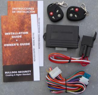
Remote Keyless Entry (RKE) capability was retrofitted using Access2Communications' Bulldog KE1702.
This brand & model was one of many available for $30-$50.
This post is merely to confirm that the features matched the application and got the job done.
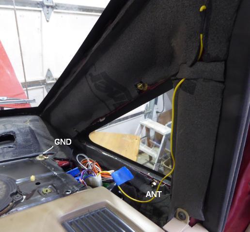
The box rests under the right-hand triangle window trim.
Four connections pass thru some split loom to the door lock relay mounted on the outside wall of the footwell.
A GND lug attaches up top.
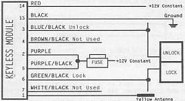
The Aerostar's power lock method has the lock buttons group onto two active-high signal buses, one for lock, one for unlock.
The RKE splices directly onto these two buses and looks like just another set of buttons being OR'd with the existing.
RKE wires...
It is convenient to splice in the RKE at plug to the existing relay module.
All the wire are in one place and there is no need to cut existing.
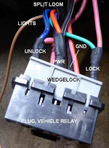
Aero wires.
- Solid black = GND
- Blk/Wht = PWR
- Pink/green = Lock
- Pink/yellow = Unlock
The splicing procedure is...
- Unplug from the Aero relay module.
- Untab the wedge lock and set aside.
- With a very small screw driver poked into the end of the plug, releasing the pin(s) being spliced.
- Using a knife, cut away a half-inch section of the insulation starting about 1/2" from the pin and ending at 1".
- Solder in the inbound wire along this section.
- Apply shrink tubing, wide enough (~5/16") to fit over the exiting socket.
- Reassemble.
*** Additional features ***
Note, the solid brown wire is to operate user supplied relay(s), and doesn't necessarily go down into the footwell.
My review of the Aero schematics conclude that one relay is required for each corner light.
There is also a possibility for two paired.
Either way, that's a bit too ambitious for me at the moment. Maybe some other day.
The relay supplied is most likely intended (by A2C) to be used for starter lock out.
There is also a channel and button for trunk (or any other repurpose).
This brand & model was one of many available for $30-$50.
This post is merely to confirm that the features matched the application and got the job done.

The box rests under the right-hand triangle window trim.
Four connections pass thru some split loom to the door lock relay mounted on the outside wall of the footwell.
A GND lug attaches up top.

The Aerostar's power lock method has the lock buttons group onto two active-high signal buses, one for lock, one for unlock.
The RKE splices directly onto these two buses and looks like just another set of buttons being OR'd with the existing.
RKE wires...

It is convenient to splice in the RKE at plug to the existing relay module.
All the wire are in one place and there is no need to cut existing.

Aero wires.
- Solid black = GND
- Blk/Wht = PWR
- Pink/green = Lock
- Pink/yellow = Unlock
The splicing procedure is...
- Unplug from the Aero relay module.
- Untab the wedge lock and set aside.
- With a very small screw driver poked into the end of the plug, releasing the pin(s) being spliced.
- Using a knife, cut away a half-inch section of the insulation starting about 1/2" from the pin and ending at 1".
- Solder in the inbound wire along this section.
- Apply shrink tubing, wide enough (~5/16") to fit over the exiting socket.
- Reassemble.
*** Additional features ***
Note, the solid brown wire is to operate user supplied relay(s), and doesn't necessarily go down into the footwell.
My review of the Aero schematics conclude that one relay is required for each corner light.
There is also a possibility for two paired.
Either way, that's a bit too ambitious for me at the moment. Maybe some other day.
The relay supplied is most likely intended (by A2C) to be used for starter lock out.
There is also a channel and button for trunk (or any other repurpose).
#14
11-11-2018, 10:32 AM
USB charging socket
Had 2 issues with my windshield mounted navigator, aka Garmin..
* The power plug is in the cigarette-lighter style, a horrible joke in the annals of automotive history. Needed a more reliable connection (as I drive into a mission critical decision point.)
* Phones and tablets were stealing the only socket up front. Choice, either navigate or charge that other thingy.
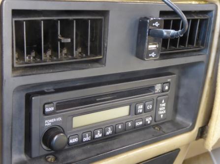
Here, a MicTuning brand, marketed as a Toyota retro/replace.
Big cavity behind the bezel. Was positioned off center because I anticipate a (unrelated) rocker switch coming in the future.
Yes, it looks a little ugly. I had assumed incorrectly a more flush mount. Didn't realize until it was installed.
On the backside, used hot glue to lock in the tabs that were designed for a thicker panel.
Comes with a quick splice harness. I grabbed the switched +12 that was going to the radio.
Decided that grabbing the Always Powered was a bad idea. I would forget, out in the middle of no where.
Lit up with a blue LED that could be a distraction at night. Will prob take a marker pen to them.
* The power plug is in the cigarette-lighter style, a horrible joke in the annals of automotive history. Needed a more reliable connection (as I drive into a mission critical decision point.)
* Phones and tablets were stealing the only socket up front. Choice, either navigate or charge that other thingy.
Here, a MicTuning brand, marketed as a Toyota retro/replace.
Big cavity behind the bezel. Was positioned off center because I anticipate a (unrelated) rocker switch coming in the future.
Yes, it looks a little ugly. I had assumed incorrectly a more flush mount. Didn't realize until it was installed.
On the backside, used hot glue to lock in the tabs that were designed for a thicker panel.
Comes with a quick splice harness. I grabbed the switched +12 that was going to the radio.
Decided that grabbing the Always Powered was a bad idea. I would forget, out in the middle of no where.
Lit up with a blue LED that could be a distraction at night. Will prob take a marker pen to them.

Thread
Thread Starter
Forum
Replies
Last Post
optikal illushun
Pre-Power Stroke Diesel (7.3L IDI & 6.9L)
49
07-25-2023 11:20 AM
Jesser02EX
1999 - 2003 7.3L Power Stroke Diesel
88
11-05-2021 08:38 PM
1996_5.8
1973 - 1979 F-100 & Larger F-Series Trucks
5
07-31-2018 11:55 AM
sere0501
1961 - 1966 F-100 & Larger F-Series Trucks
3
04-21-2018 05:17 PM
NBC-Steve
1973 - 1979 F-100 & Larger F-Series Trucks
19
07-06-2017 02:07 PM