When you click on links to various merchants on this site and make a purchase, this can result in this site earning a commission. Affiliate programs and affiliations include, but are not limited to, the eBay Partner Network.
7.3L battery light with good batteries & new alternator
I have a 2000 F-250 7.3L that has had the battery light stuck on for several years. It initially came on after the truck had been sitting for several months and the batteries were not fully charged. It started (barely) and then the battery light turned off. Within several minutes the battery light came back on and has never gone away. I have replaced the alternator twice just to be sure, and both batteries are new and have been checked out multiple times. I have checked the fuse box and #'s 6 & 7 are good along with all the rest of the fuses. I'm confident this is not the batteries or the alternator. I'm stumped. Anybody got any ideas on how to diagnose this and fix it?
Have you used a multimeter and checked the bolt on the back of the Alternator for charging voltage? Is that voltage making it to the batteries? Check this after GPR has shut off. Both voltages should be above 13V to 14.4v. Have you checked the fuses with a test light? If you unplug the connection at the alternator does the light go OUT?
You can have several reasons for the light to be on. One is a poor connection of the control plug at the alternator, a damaged wire in the gauge to alternator control, or a bad diode in the alternator. With a bad diode, you can see a reasonable voltage, but the current may not be as good.
I did a hastily made video for a person who was having alternator issues, not the best quality but it goes through checking the connections and batteries.
never use your eyes to check a fuse..... not since the glass tube fuses... a test light or multi-meter.
as you will NEVER See the crack in the fuse.. only a dead short POP..
bad ground, bad connector, bad/damaged wire.....
its been on for several YEARS ??????????????????????
Yes, light has been on for maybe two years. Everything else works just fine. No problems with starting, charging or keeping a charge. Like I said, I've gone trough two brand new alternators to address this light since its been on so I'm confident in eliminating the alternator itself as a suspect. The batteries are relatively new and haven't been subjected to a bad alternator, and they have checked out several times for load test and output. This has to be a secondary issue: fuse, wiring, etc. I will take Chuck up on his fuse testing advice. I have to admit that a visual inspection is suspect on an 18 year old fuse. Otherwise, I'll check out Toomanytoys' videos and start checking for wiring breaks. I cleaned up the alternator connections and gave them a little dielectric grease so I think it has to be downstream from there.
Update: I watched Toomanytoys' first video about ten times and followed most of his tests with my multimeter:
Ignition off:
12.68v both batteries, connected
13.0v Driver's battery, disconnected
12.83v Passenger battery, disconnected
0.26v Orange (A/sense) alternator harness wire (+ on wire, - on battery - terminal)
0.11v Green (B/control) alternator harness wire (+ on wire, - on battery - terminal)
Ignition on, engine running:
14.41v both batteries connected
Ignition on, engine not running:
0.26v Orange (A/sense) alternator harness wire (+ on wire, - on battery - terminal)
12.41v Green (B/control) alternator harness wire (+ on wire, - on battery - terminal)
The orange wire seems to be an obvious problem. According to Toomanytoys, the orange should read battery voltage at all times, and mine reads 0.26v at all times. I started it up with this harness unplugged and for the first time in two years, no battery light. As soon as I plug it in, battery light comes on. Obvious solution would seem to be just leave it unplugged, but this must not be an option so on to diagnosing the orange wire. I can trace the orange/gray sense wire to the passenger side wire bundle on the firewall, then it disappears. A poster above shows it going to the solenoid on his '99. On my 2000 orange/gray definitely does NOT go to the solenoid (not as a small gauge orange/gray wire anyway), and the fusible link location is a mystery. Wiring diagram makes it appear that the orange/gray wire turns into a gray fusible link. But what color after that? ...and where does it go? I can't see an obvious location for the fusible link.
I re-checked #6 & 7 fuses and they are good
�That�s why I asked above if the light goes out if you leave it unplugged � If the light goes off when you unplug it there�s a ground issue.
The 7.3L layout is a little different than the 6.0L. which is what that video was for. Yet the same.
However, the orange/light blue wire is to sense the battery voltage and for the alternator regulator to adjust the current output to the batteries and system at the designed voltage. If the OG/LB circuit has a blown fusible link, it had no idea what the output it should be controlled too.
The light green/red wire from the gauge turns on the alternator. If the alternator is not supplying the "right" voltage, the circuit is designed for the light to glow. There's a difference in voltage on both sides of the light bulb. So if the key is on but the engine is not running, the alternator is the ground. With key on engine running, the alternator should be putting out a clean 13.8 to 14.4 volts, and that voltage is on both sides of the light bulb.
Disconnecting the plug removes any "turn-on" signal to the alternator. So no alternator function at that point. It also makes the dash battery light an open circuit, so it's not going to light.
As I stated, the voltage has to be balanced on both legs of the dash battery light. One side is to the alternator, the other to the positive battery through the trucks circuitry. If the alternator has bad diodes, and even rebuilt alternators can have bad diodes, the battery light will go one because it's not clean voltage on the alternator side.
2003 7.3L
I would assume that if it's the fusible link on the orange wire, or some kind of break, I should be able to do a continuity test to confirm it. But I can't find the terminus for that orange wire. I guess I will have to start disassembling things to figure out where it goes.
Do you have a link for the whole manual you're referencing? It looks like there's more detail on this elsewhere in the manual. By the way, I thought your video on this was quite good. I referenced it while I was running the meter to make sure I was doing it right. Very helpful.
The post just above yours may help. Files are on a DVD.
You can do a continuity check of the fusible link just by going from the connection at the alternator to the positive battery post. But 12.6v should also be at that connection no matter if I'm reading the 7.3L diagrams, just like the 6.0L is.
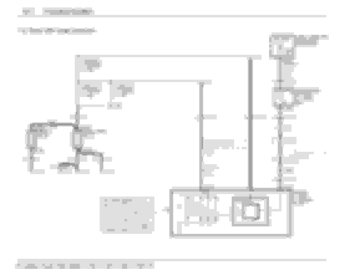
I'm getting 0.26v ignition on or off on the orange wire. There's obviously something wrong with the circuit and it's apparently just getting a little voltage leakage. I just need to find it's next connection point so I can narrow down the problem area. From your diagram it appears to join the main alternator black/orange wire at some point. I'm no electrical engineer so I'm not entirely sure that I'm reading the diagram correctly or what it means.
So from the notes on the left of the diagram it appears the A circuit primarily supports internal generator/alternator functions. The orange "OG/LB" wire is the "sense" input of the A circuit, meaning that it's providing sample current TO the generator/alternator FROM the main charging circuit? I assume that's for the regulator to "sense" actual voltage on the main charging circuit so it can adjust output. However, from the diagram it appears that the OG/LB wire simply loops around and merges with the black/orange main output from the generator/alternator at some point. I guess by this point system voltage is a more accurate read than if it were just simply pulled directly from main output on the generator/alternator? I would think my charging system would be showing some symptoms of not having any "sense" input for the regulator/field function, but all appears just fine. Regardless, OG/LB definitely does not have continuity and is severed somewhere. So locating the "S1011" (as shown on your 2001 manual) junction of the OG/LB wire and the black/orange generator/alternator main output wires seems to be the thing I need to diagnose where OG/LB has failed.
Assuming all my conclusions above are correct, OG/LB has a break in the wire somewhere, the fusible link has done its thing, or the OG/LB connection to the black/orange generator/alternator main output wire at "S1011" has failed. Any help you can offer as to where OG/LB joins to the generator/alternator output is appreciated.
It's a shame those service manuals aren't readily available online. I was able to get downloads for a whole series of Jeep service manuals through a forum.
Since I no longer have a 7.3 I can't help on the physical work. Ford does the same thing on the 6.0, and most of its other vehicles sense downstream of the alternator but before the batteries. Some other manufacturers eliminate that entirely and connect the sense internally.
I'm using a Leece-Neville 230a alternator that supplies higher then Ford/Int designed 14.4v max, and I tried to work with L-N to get a solution. I say it was their regulator, them saying it wasn't. One of the things I did was loop the sense circuit to the power outpost. It can be done, but it should be fused and you can readily buy fusible links at the auto parts store to do that if you need to. Sensing more towards the batteries eliminates any losses from connections, although with sliced connections (the round dots in the diagrams) there shouldn't be.
7.3L guys, don't get any wild ideas about the L-N 230a, that voltage issue could be disastrous without a GPCM to control the glow plugs overvoltage and burn off tips, resulting in a lost motor.
If you can get Y2KW57's attention, he would be an excellent resource for your issue with a 7.3L.
So I disassembled some things yesterday to see if I could locate my problem. I was able to trace the OG/LB wire from the alternator to the central junction/fuse/relay box on the driver's side engine compartment; no breaks or shorts. As described by others, mini-fuses #5, 6 & 7 all have continuity with the OG/LB wire at the alternator. There are two OG/LB wires leading to/from the central junction box. One comes directly from the alternator to the fuse box, and the other goes from the fuse box and disappears into a huge wiring harness bundle on the firewall. The diagrams I have show an OG/LB wire going to the gauge cluster. I found another one not shown in any diagram that travels through the transverse/upper firewall wiring harness and terminates in a dead-end near the passenger side battery. I couple of days ago I was only getting 0.26v on the OG/LB wire at the alternator, obviously just some leakage. After fiddling with the fuse box but not really fixing any obvious problem, I now have about 4.5v. But interestingly, the dead-end OG/LB wire that terminates near the passenger side battery has the full 12.68v. Voltage at mini-fuses #5, 6 & 7 all reads the same as at the alternator, about 4.5v. When I pull one of those mini fuses, voltage goes UP to about 5.5v in the other two. There's no obvious corrosion, missing or loose connections. I cleaned up the fuses with a wire brush and put a dab of dielectric grease on the them.
I am stumped. I'm really doubtful that I can fix this problem without dissecting the entire wiring system, thus making a cure far worse than the disease. The alternator "sense" input is simply bunk and not serving any useful purpose, but other than the battery light the vehicle has run just fine for two years like this. I'm tempted to just unplug the alternator sense & control harness just to make the battery light go away. The sense circuit clearly doesn't work, but if the alternator doesn't have the control wire, will it just cease putting out current and deplete my system?
I suppose I could just abandon the existing OEM sense circuit entirely and create my own. It seems to just be raw system voltage that could be drawn from just about anywhere, but there's a reason why the factory put three fuses on the same circuit. I just don't know what that reason is.
Before I went through all that I would have done the diode check. It won't clear up the sense circuit, but anytime the dash light is on it's a basic test.
Other diagrams and that's about all I can help you with on a 7.3L.

 10-12-2018, 10:13 PM