
3g 200A alternator wiring question and volt/ammeter install
#1
 11-27-2017, 12:11 AM

Join Date: Sep 2013
Location: Park Hills, MO
Posts: 49
Likes: 0
Received 0 Likes
on
0 Posts
3g 200A alternator wiring question and volt/ammeter install
Hi, I have installed a Powermax 200A alternator on my 1992 F-250 5.8l and I haven’t road tested it yet but so far I’m not seeing any real difference so I was wondering if someone would be willing to show me a drawing of the alternator wiring to be sure that I got it right and lead me to an ammeter that’s accurate and reads up to atleast 225A because I want to make sure that the alternator at highway speed is actually putting out 200A and I want to make sure that the way I have it wired now that it’s right and not discharging. I hooked the green w/ red back to the green w/ red that it was originally hooked to (I used a new plug), I hooked the white to the stator on the new alt, and the yellow on the positive alt post. Then I ran a 1/0 wire to a 200A breaker, ran a 1/0 wire from the breaker to the starter solenoid, and then from the same solenoid post I ran a 1/0 wire to the pos on the battery. I ran a 1/0 wire from the alt case (it has a bolt hole for a ground on it) to the neg on the battery, a 1/0 from the neg on the battery to the frame, and then to the engine block, and I ran a 1/0 from the battery neg to the body. Then I hooked back up the ignition hot wire to the solenoid where it originally came from and hooked the starter wire back to the battery where it came from. All the wires that didn’t need disturbed were left where they were. It starts right up, in fact the starter turns over a lot better than it used to, so I think that I got it right, but my volt gauge in the dash still bounces a little back and forth about 1 volt, maybe 2. I honestly just think the factory gauge is wore out, so I’ve been trying to find a volt/amp meter that’s accurate, don’t cost a fortune, covers atleast 0-225 amps, but all I’ve found is these Chinese digital gauges on E-Bay that are 0-300V/0-500A w/ a 500A/75mV shunt and I’m not sure if they’d even work right on it, I even seen one review that said that the amps didn’t read right, which is the real reason that I want a gauge is to accurately know what amps this things putting out, and all the directions for hooking it up are in Chinese, and I don’t read Chinese. Does anyone have any suggestions or atleast can confirm for me that I have the alternator wired right? Any knowledgeable info would be appreciated. Thanks in advance.
#2
11-27-2017, 12:34 AM
Posting Guru
Don't worry about installing an ammeter; they are completely useless. Install a volt gauge instead. The alternator will only put out 200 amps if there is a load that requires it. Only enough electricity that is required to run a load is produced. Meaning you will only see about 40-50 amps used during normal driving, after the battery has charged. It is also not really necessary to ground the alternator; it's contact with the engine is ground enough.
This is the diagram I always use to wire a 3G alt.
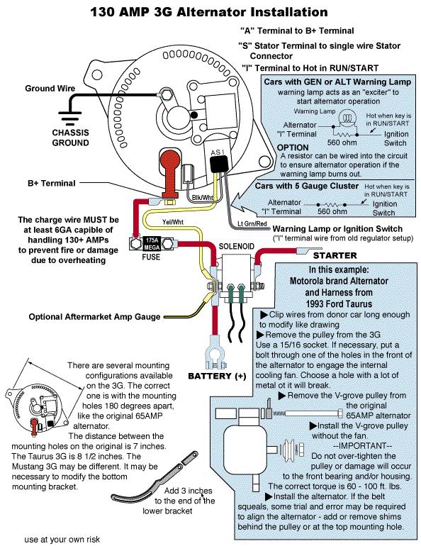
This is the diagram I always use to wire a 3G alt.
#3
11-27-2017, 04:21 AM
Join Date: Sep 2013
Location: Park Hills, MO
Posts: 49
Likes: 0
Received 0 Likes
on
0 Posts
#4
11-03-2019, 03:29 PM

According to the wiring diagram I have for 84, it shows that the A+ terminal on the regulator (white/yellow) goes to the ammeter which would make it your battery sense. There are a lot of connections that this goes through, including the printed circuit board on the instrument panel that could cause a low voltage to the sense terminal of the voltage regulator. I mentioned this in a previous post. Strip the A+ wire back a bit and connect with a jumper wire to the battery side of the solenoid. If the pulsation stops you can hook it there permanently. However your ammeter will no longer work but thats the case on most Fords with an ammeter. Just check your voltage at the battery and see if it's steady.

Thread
Thread Starter
Forum
Replies
Last Post
SuperDuty93
1973 - 1979 F-100 & Larger F-Series Trucks
9
06-13-2015 12:11 PM
MeatRo
Electrical Systems/Wiring
10
04-25-2015 11:19 AM
firerescue9
1987 - 1996 F150 & Larger F-Series Trucks
5
08-30-2013 04:59 AM