When you click on links to various merchants on this site and make a purchase, this can result in this site earning a commission. Affiliate programs and affiliations include, but are not limited to, the eBay Partner Network.
To begin, I found a mega-clean original head unit from an Aerostar - I actually pulled two from two vans, but these were available in many Ford/Lincoln/Mercury vehicles including E-Series and F-Series throughout the 90's. I pulled them for 11$ each. I would recommend getting the head unit removal tools from Wal-Mart - they are about 6$ and make removing the radio a 15 second deal. Here's a video of how simple it is using coat hangar wire:
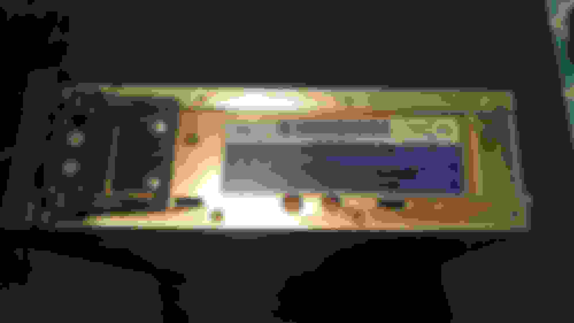
You will notice that the "eject" button is missing - removed it before I shot these photos, and I had spent hours of trial and error/tracing leads inside the radio to find the answer is all accessible from the bottom
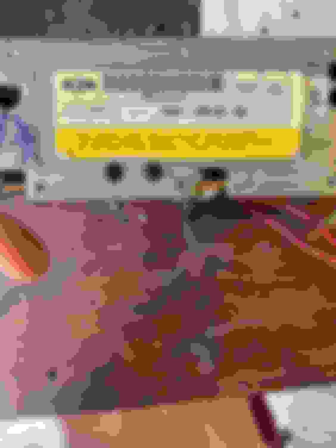
The engineering/stamping # of this particular radio is F68F-19B132-CA. This is NOT a good part # - you would have to have a dealer cross this # for you.
Here's a photo of the radio with the bottom cover plate removed - this photo was taken after I had tested out the modification. Our work will be done on the corner adjacent to where the rear connectors are located that provide power and output signal to the speakers in the vehicle.
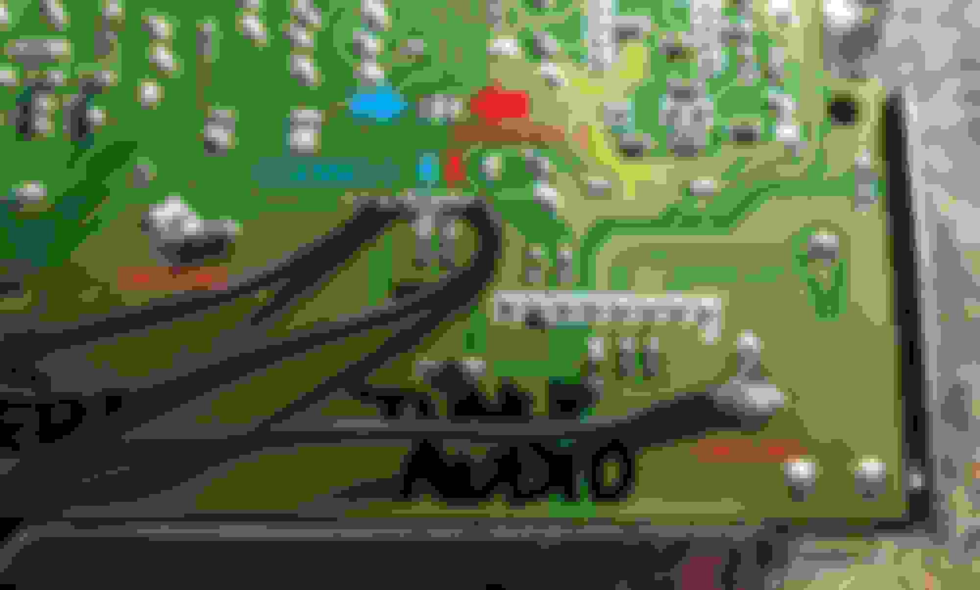
The solder work on the radio itself is very straightforward. You will need three pieces of wire - depending on where you mount the jack, the length may vary. One wire will be soldered to one the grounds labelled on the photo. Another will be soldered to one of the two locations noted on the red "Channel 1" pads, and the remaining wire to one of the two blue "Channel 2" pads. They do not have to be on the same side of the two corresponding pads - these pads are linked on the opposite side of the board by a jumper wire - i only give this option if you are not comfortable soldering two leads on pads so close to each other. Once you have completed your solder work, get your 1/8" jack and solder it according to the wiring diagram provided with the part. I was not able to figure out which channel is left/right on the board, which is why I left it as "Channel 1/2" in the photos.
What we have done is tap into the circuit running from the radio "tuner" in the radio to the pre-amp circuit - this retains the functionality of the cassette deck should it be needed, and also retains the functionality of the radio when nothing is plugged into the end of the aux cord. I tried for hours to find a way to tap into the cassette circuit but could not find a way that did not require having a gutted cassette in the deck, and the annoying "whirring" sound of the motors running.
I found when you plug the aux cord into the jack, there is no change to the functionality of the radio - you can change the volume,stations, everything as normal. I ran the aux cord down through the ash tray, and left it coiled up. Once you plug in your aux in source to the other end of the cable, the tuner goes quiet and the head unit takes the signal from the player of your choice! I use my phone as an Mp3 player/video player, but I can imagine you can hook up cd players/Satellite radios using this method as well.
I did this because I cannot stand aftermarket head units - and they only seem to drive up the likelyhood of theft. I looked for hours trying to find a guide on this particular style of Ford radio, and saw most of what been done was on the later double-DIN radios in the super duty/E-series/Ranger/Explorers. I have tried the cassette/FM adaptors and modulators, and even found a bluetooth cassette adaptor that worked fairly well for awhile. Ultimately, all of these items did not meet my expectations for convenience, reliability, or simplicity - or a combination of those three factors. I am not responsible if you set your house or truck on fire or record it to put on WSHH.
Last edited by MR KROGOTH; 08-27-2017 at 06:24 AM.
Reason: Spelling/punctuation, added removal video
Nice work. I bought a factory CD player that someone did this too.. it was a nice touch till the CD player part crapped out
I pulled a factory CD player single DIN unit out of an econoline last weekend before the storm. Did yours have the amplifier unit too? I pulled out the amp and cut enough for pigtails to make it work but havent played with it yet.
I pulled a factory CD player single DIN unit out of an econoline last weekend before the storm. Did yours have the amplifier unit too? I pulled out the amp and cut enough for pigtails to make it work but havent played with it yet.
Yes, all the early CD players had the external amp
I pulled a factory CD player single DIN unit out of an econoline last weekend before the storm. Did yours have the amplifier unit too? I pulled out the amp and cut enough for pigtails to make it work but havent played with it yet.
Have you figured out this mod with the CD players as well as the cassette player radios? If so, please post pics like you did with the cassette radios. Thanks!!
Have you figured out this mod with the CD players as well as the cassette player radios? If so, please post pics like you did with the cassette radios. Thanks!!
If you can take pictures of the board on yours I can probably figure it out.
Hi, I have what appears to be the same radio. I have a different part number, and the pin out looks slightly different in that lower corner of the board. I have soldered into what I believe are the channel 1/2 locations. Bluetooth does take over when activated, but sounds terrible. Any advice on what could be my problem, or where the right place to solder into is. Have tried two different ground spots. Have tried three different spots for channel 1/2.
Also tried these two spots as channel 1 & 2.
Last edited by halfasst10; 04-21-2022 at 12:19 PM.
Hi, I have what appears to be the same radio. I have a different part number, and the pin out looks slightly different in that lower corner of the board Any advice on what could be my problem, or where the right place to solder into is. .
Different part number, different radio.
My first guess is that you do not have 'Premium Sound' head unit, that outputs 'pre-out' or 'pre-amp' out.
You need a head unit that ouput's to an amp, and of course an amp.
I may be wrong.
If the OP(thread starter) could post a pic of the back of the stereo, that would clear that question as to whether or not the head unit needs an amp or not.

 08-26-2017, 10:43 PM