When you click on links to various merchants on this site and make a purchase, this can result in this site earning a commission. Affiliate programs and affiliations include, but are not limited to, the eBay Partner Network.
He's running the original 6 volt system - didn't go 12V, didn't go alternator. His amp meter isn't any more dangerous than as it left the factory in 1949. With all due respect to Ron Francis and his very capable staff - this particular tech note is vague at best.
That particular tech articular is not just vague it is down right misleading incorrect and wrong. All I can say it is well worded pitch to sell more product and get more money from their customers.
Apparently they have no clue how a shunt amp-meter even works the full amperage of the alternator/generator DOES NOT have the full amperage from the charging system going to the dash. There could be as little as 1ma going to the amp meter. which is on par to the other gauges and less than lighting.
Actually a shunt amp meter is safer than the loop as the current is much much lower for the shunt Amp meter.
More proof you can not believe everything you read on the internet.
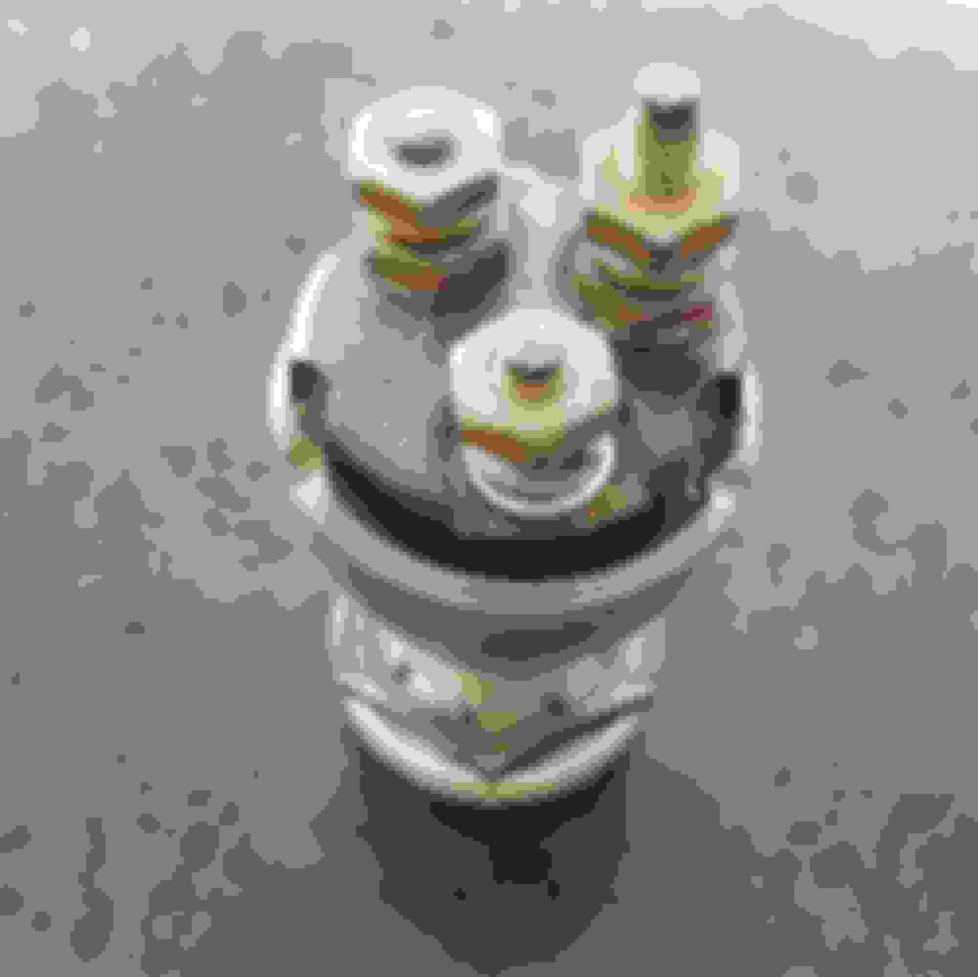
Another wiring question. The wiring diagram shows the wires on the ignition switch going to the battery, gauges and coil. The switch I have only has the BAT terminal labeled. The only thing that distinguishes the other two terminals is that one is considerably taller than the other. Does it matter which one goes to the gauges and which one goes to the coil?
I would guess the taller terminal is for GA (which is not just gauges, but any accessories). A quick check with an ohmmeter or continuity tester will confirm.
I just read that Ron Francis tech tip and it almost left me speechless. Whoever wrote it up is pretty (say very) ignorant of automotive ammeters and wiring, and assumes the reader is just as ignorant to believe it (I find it very condescending). The Ford ammeters that have the induction loop on the back are the safest type available. They utilize the Hall effect for operation, and thus no current flows through the meter at all. https://en.wikipedia.org/wiki/Hall_effect
Ammeters that have terminals on the back are all internally shunted. Internally shunted ammeters are limited to 60-0-60 (60 amps) due to shunt size. Ammeters of greater capacity are externally shunted. https://en.wikipedia.org/wiki/Shunt_(electrical)
Ron Francis' writer is speculating and hypothesizing the safety risks in order to sell products. I have been using gauges and meters throughout my 60-plus year career, and subscribe to numerous trade journals as well as being a past member of the SAE and SNAME. I have never, ever heard of an ammeter blowing up or causing a fire.
I would guess the taller terminal is for GA (which is not just gauges, but any accessories). A quick check with an ohmmeter or continuity tester will confirm.
Ross, I appreciate your reply. Unfortunately, you're giving me credit for actually knowing what I would be testing for. As I said at the beginning, I'm pretty ignorant when it comes to electrical things. Not sure I should even be allowed to work on the wiring on the truck.
I would guess the taller terminal is for GA (which is not just gauges, but any accessories). A quick check with an ohmmeter or continuity tester will confirm.
I think Ross is right. If you look at your wiring diagram, it shows the back of the ignition switch. With the battery terminal pointing down, you'll see the GA terminal is to the top right (2 o'clock position), and the coil terminal is at the top left (10 o'clock). As Ross was pointing out in your picture, the GA terminal is the longer one, and it is pointing to the top right, with the Battery terminal at the 6 o'clock position. I think that will work out......
Ross, I appreciate your reply. Unfortunately, you're giving me credit for actually knowing what I would be testing for. As I said at the beginning, I'm pretty ignorant when it comes to electrical things. Not sure I should even be allowed to work on the wiring on the truck.
Do you have a multimeter? They are < $10 at Harbor Freight for a cheapo one, which is good enough for 90% of what you need. (They even pass them out free during some "sales").
Switch it to Ohms, or if it has it, Continuity. Put one lead on the BAT terminal, turn the key to ACC, and touch the other probe to one of the other posts. Whichever one has near-zero resistance (ohms) or continuity (either a beep or something in the display) is your GA terminal. Turn it to IGN, repeat, to confirm BOTH posts have continuity.
Thanks for your patience and the explanation. I do have a multimeter although I haven't used it in a while. I'll dig it out and see if I can figure this out.
The results are in. The switch has three positions but the key can only be removed in the center position. I assume ACC is to the left from the center position and IGN is to the right. When in the center position or when turned to ACC neither of the posts show continuity with the BAT terminal. When turned to the right, both posts show continuity (zero ohms) with the BAT terminal and with each other. I assume I can use the switch as an ignition switch as long as I don't care about the ACC position.
I don't think it original since it's my understanding that the original switch was just off and on without an accessory position. Also, it doesn't have original keys although that may not mean much since I'm sure a lot of original keys got lost over the last 60 years.
My '52's OEM switch has ACC position. Can you post a pic of the front of your switch? I may have one. (48050's are different than 51-52 at the opening in the dash)
 08-11-2017, 12:24 AM