When you click on links to various merchants on this site and make a purchase, this can result in this site earning a commission. Affiliate programs and affiliations include, but are not limited to, the eBay Partner Network.
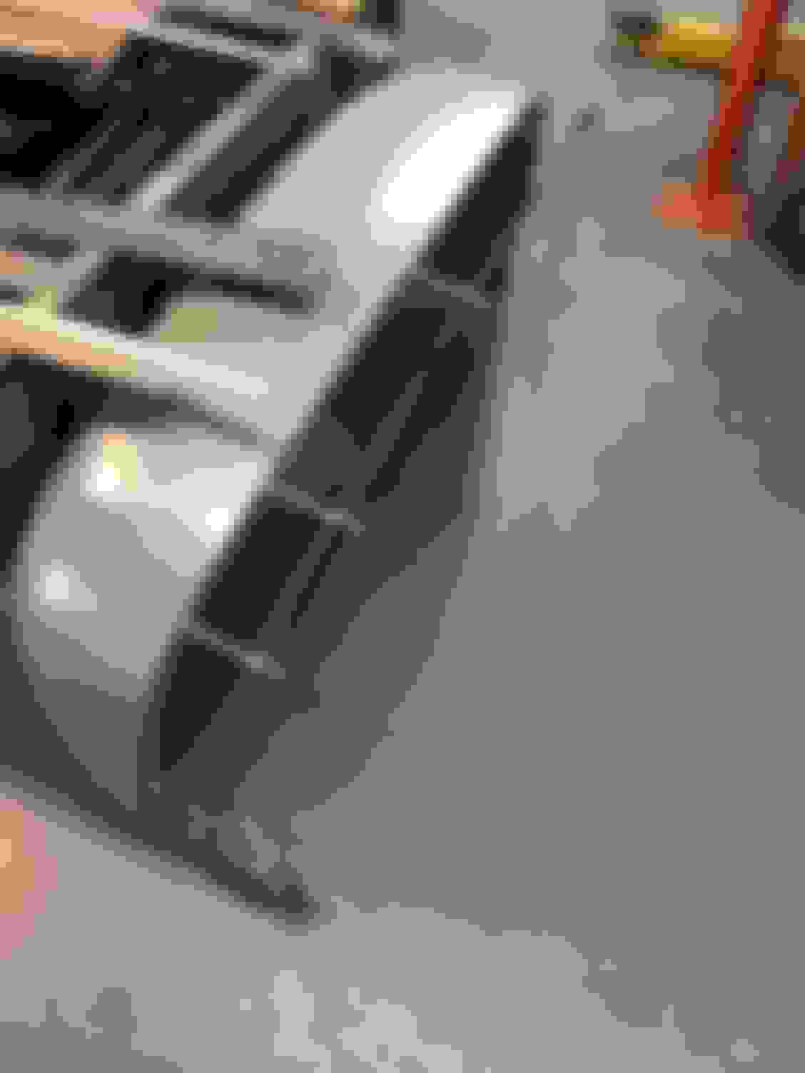
We now have the bulk of the rear fender work done: 4" width extension metal all tacked in place; Fender position calculated and set / holes drilled and mounted
We have the truck frame sitting level on jack stands. We also made sure that both the cab and bed are mounted level on the level frame.
We set the truck at what we believe to be to normal drive height.
At this point, the bottom flange of the front fender that will bolt to the running board is 9 1/4" off the ground... that is what primarily determines my rear fender height ... the front bottom flange of my rear fender that bolts to the running board will also be 9 1/4" off the ground... my running boards will be fabricated after I get the fenders squared away.
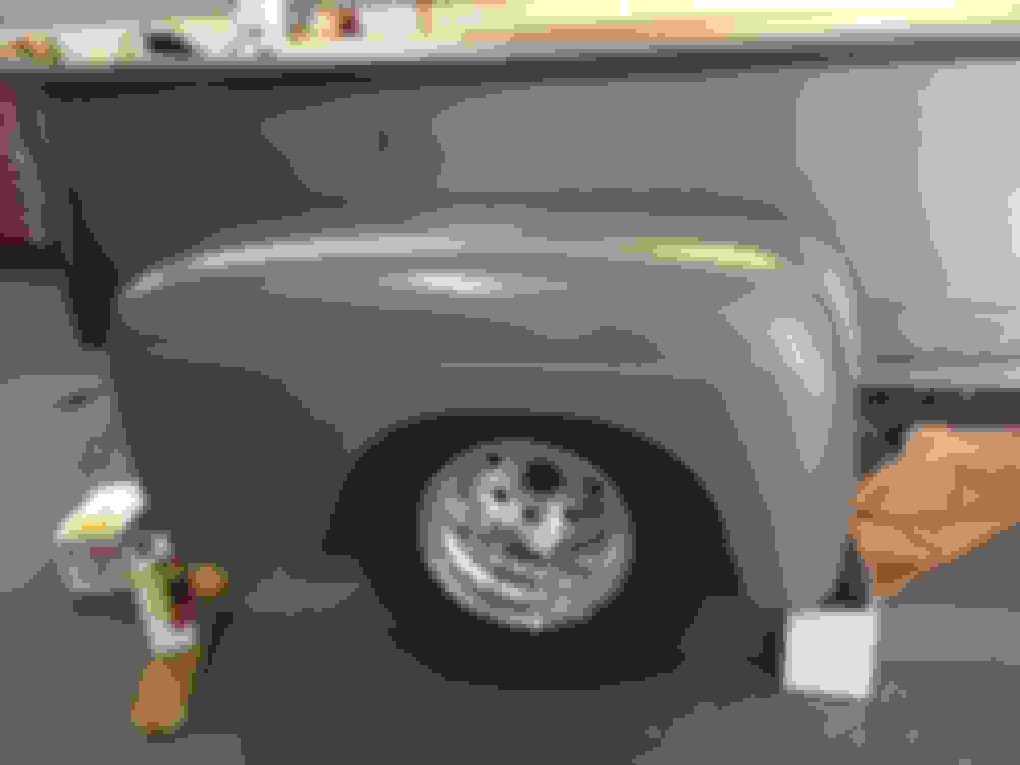
Fender propped in place ... the front / bottom edge of the rear fender matches the cab front fender
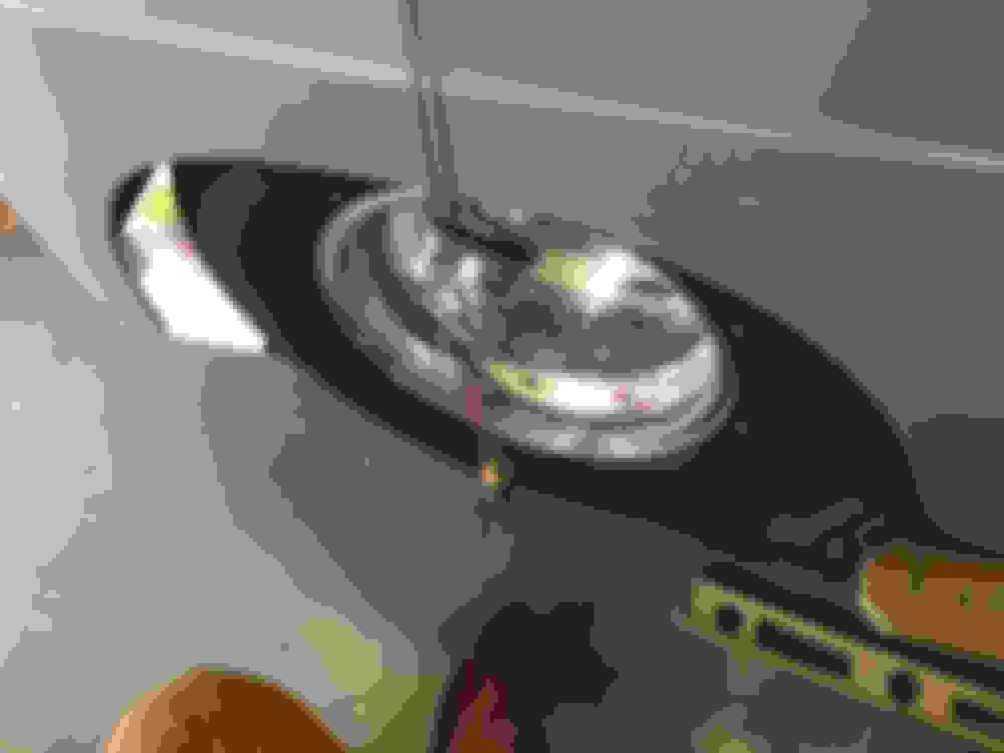
We used a plumb bob to align the fender front to back -- centered the wheel well over the tire
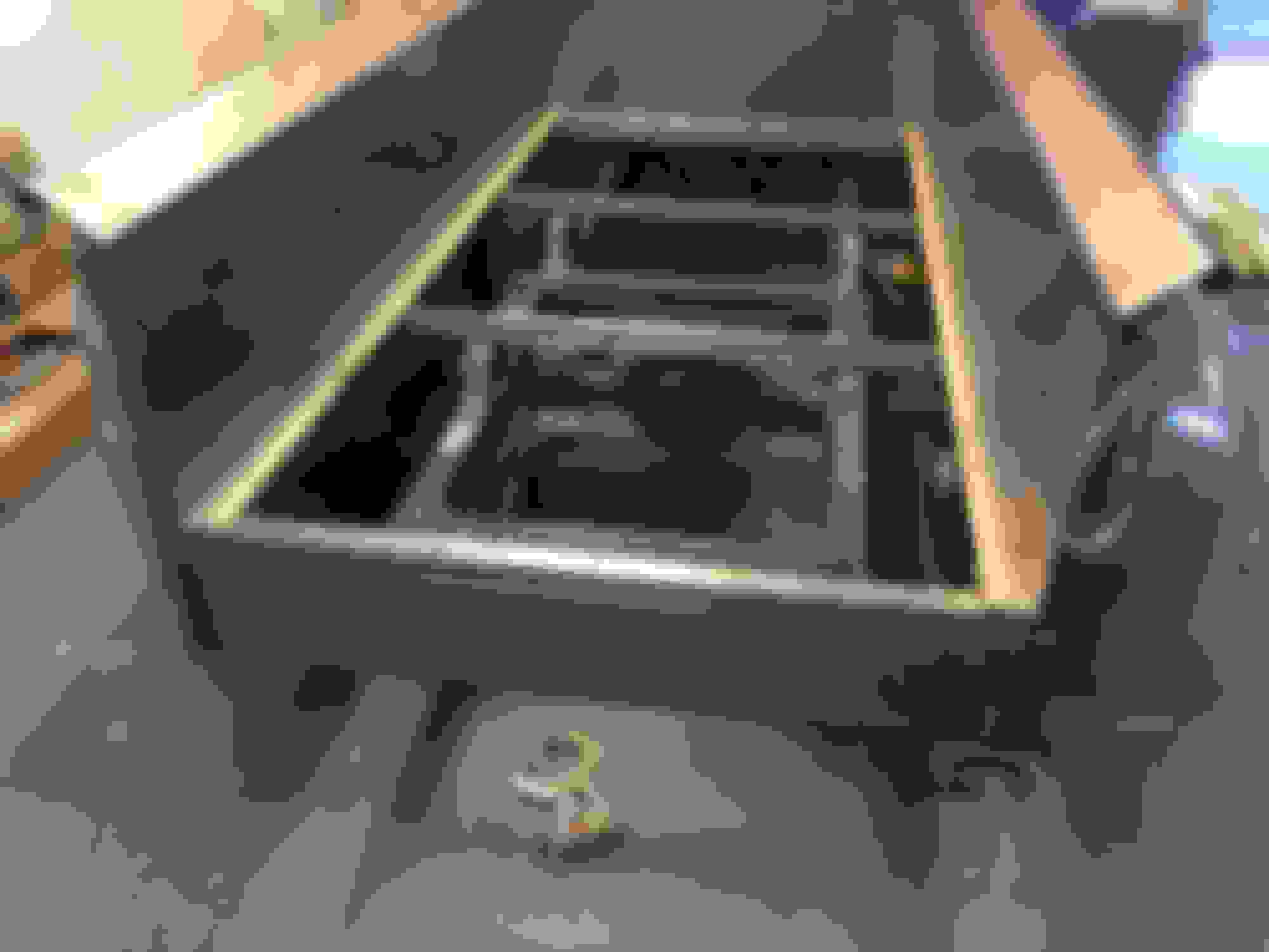
Finally, with the general height determined by matching the front fender and the front to back determined using a plumb bob, we lastly perfectly level the fender with the bed using a straight edge laying across the bed and measured down to the body line on the fender. In my case, that measurement has to be 19 1/2"
We then used vise grips to hold the fender in place; Marked the body holes with a sharp yon the bed sides and drilled 5/16" holes for the mounting points.
We had to overcome a few other small obstacles: One of the stock fender mounting holes was going to be in the bedside body line where the wood bed line was so we created a new one lower... we also first tried a cardboard pattern for drilling the holes... that was not going to be accurate so we abandoned that idea... using the straight edge on top of the bed to measure down to the body line was a last minute epiphany that came to my friend Mark as we plugged away at making the last of our placement decisions...
They have plenty of top and side tire clearance...
if we had widened these on a standard F1 build, I think they would look out of proportion ... but on this F5 COE build, they look perfect
Another step forward
The outside edges of the front and rear fenders are within 1" of each other
Hey Brian,
You are teasing us over here... So... What's that nice little Porsche(?)
over there in the corner?
Watching you extend those back fenders is a thing of beauty. You have mad skills.
Ben in Austin
1950 F1
Whoops... didn't mean to Include any distractions...
Thats actually a beautiful mid 60s 356 that belongs to a close friend and life long car enthusiast as well. It's going through a total restoration process and will be painted soon... that project will be on another thread someday... and a real head turner ... maybe I should plan to carry it around in the bed of my COE for show... it's about the right size...
Also, I wish I could take all the credit for the fabrication but that's not my forte.. we have a young man that has had loads of training and experience helping me out with most all of the body work related fabrication. I really want this one to be done right... plus it would take me MUCH longer to do everything myself.
Hopefully more pics getting the running boards and rear roll pan dialed in over the next few weeks.
I should also be getting my wiring harness / ECM programming soon as well...
still loads of mini projects remain ... auto trans linkage; fuel system; brakes; A/C, etc...
Rear Roll Pan and skirt extensions behind the rear fenders
Working on getting all the body metal in place...
the following are a few pics of the rear roll pan tacked in place and the skirt extensions behind the rear fenders.
We are going to have half circle cut outs on the bottom of the roll pan for the dual exhaust... still to come. the marked areas on the roll pan are for the tail lights and license plate that we will french in.
passenger side skirt extensions combined and formed into the roll pan
adjusted the curve / return of the rear fenders into the bed sides... tacked for now
Rear roll pan -- with the license plate and tail lights marked in. tacked for now.
Driver's side skirt extension formed into the roll pan.
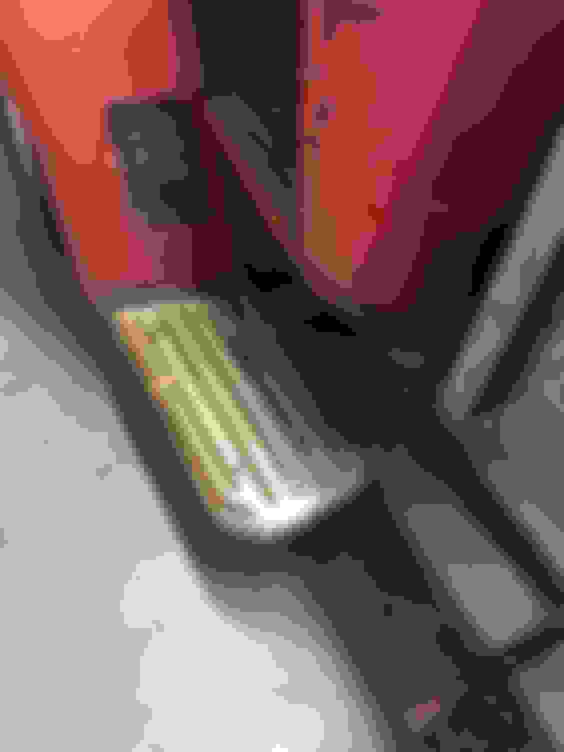
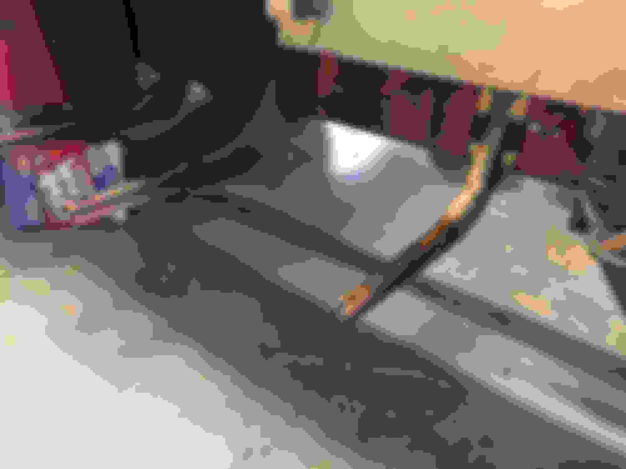
Started working on the running boards... thanks to a fellow FTE member who sent me the running board supports off of his standard F-6, I'm going to repurpose them on my COE... will have to modify/extend them a couple inches... otherwise, they are just about perfect.
original running board just temporarily sitting in place.
the additional running board support is drilled and bolted into the frame... you can see where I need to extend the additional one a couple inches.
Of the original pair of board support brackets, the rear ones need heated and bent back up about 3/4" to make them level again... years of big dudes jumping up in the truck took it's toll.
With your fab skills, I'm sure it would be very simple and no more bending! Not that big dude will probably ever be jumping on them again...
I'm thinking some LED "courtesy" lights hidden inside the bracket would make for a subtle yet useful addition. (Note not the "Ricer" style, just a white that illuminate the ground when you open the doors.)
I purchased a set of stock reproduction steel running boards for an F1 standard pickup.
I initially pulled them out of the box and compared the radius to what I have on the COE...
Because it's a COE, the "cab" is shorter than a standard F1. Almost a foot shorter.
According to at least one other FTE member, I am installing the running boards backwards... but the radius matches my front fender perfectly. and the other end was close enough to require only a minor radius adjustment to match the rear fender.
We made the adjustment to the rear radius; then temporarily held both the front and rear fenders where we believe they should be and then measured the distance. We cut approx. 10 1/2" out of the center of the running boards and re-welded the seam -- after cleaning it up, you can barely tell that we cut them.
We kept the running boards parallel to the frame.
after getting them mounted to the support brackets and bolted to the fenders, we marked them up and cut the rear flange off -- that flange will be used later... we are now working on adding a flat extension so that the flange can be placed where we want it to allow the bed to basically tie into the running board in a way that looks good.
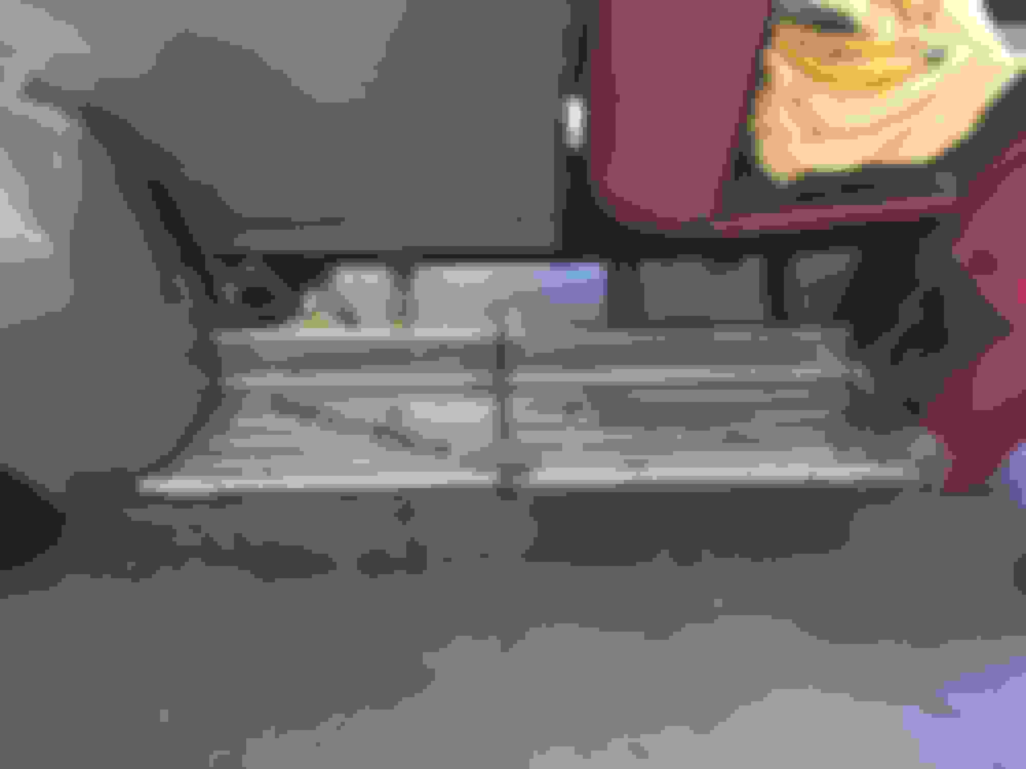
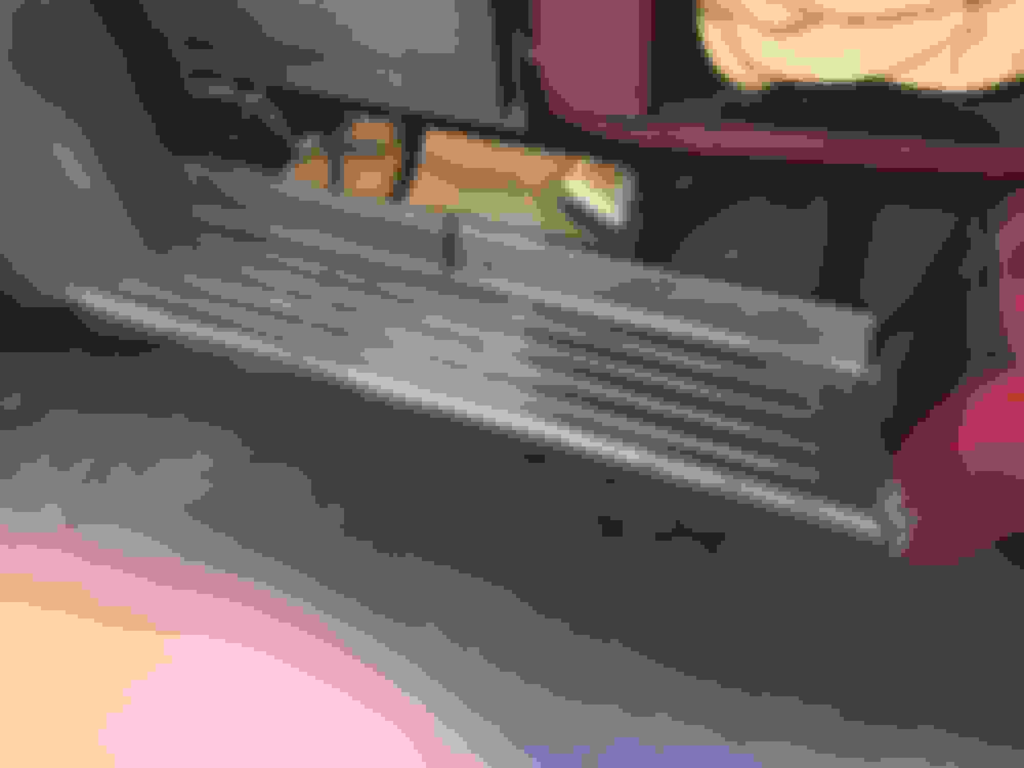
Front and rear radius is near perfect and we cut the running board / you can see the initial seam near the middle. The support strips are temporary / holding it all flat / in place.
most of the seam has been cleaned up. We are just about to cut the rear flange off / extend it back about 4"...
driver's side; Radius front and back is dialed in; length is cut and seamed; seam is cleaned up and permanent support metal has been welded to the under side (similar to the stock running boards) Rear flange cut and we are fabbing up the flat steel / prepping to re-install the rear flange that has been cut off.
the stock intake on a crown vic has the air being sucked in 90 degrees / facing the driver's side of the vehicle. This posed a problem because my right foot and the gas pedal would have been affected.
I initially rotated the throttle body 180 degrees and thought, "I'm not worried if the passenger isn't comfortable...
Well... my friend Mark wasn't buy'n it and decided to fabricate a new intake adapter that rotated the intake about 60 degrees and no there is MUCH less obstruction; none of the cab support members will need to be cut to get the Air Intake outside of the cab, etc.
It looks excellent and should work perfectly.
Note the 3/4" aluminum plate under the throttle body... it looks like it's going to work perfectly.<br/><br/>
View of the plate adapter from the driver's side interior.


 05-24-2017, 06:20 PM