When you click on links to various merchants on this site and make a purchase, this can result in this site earning a commission. Affiliate programs and affiliations include, but are not limited to, the eBay Partner Network.
Being the shortest wires might mean something but I don't think it's that.
YIKES, sorry this post is so long!
The glow plugs are internally self regulating by design so they won't overheat. I am assuming that is with a properly working controller. I've read the Beru glow plug patents and they are unique. One of the special components aside from the alloys used in the coils, tip etc. is the formulation of the ceramic powder that is packed around the internal coils to prevent them from shorting out.- So they ARE different and better than other manufacturer's glow plugs in this application, at least for as long as those patents were maintained.) At least, they should work very well and last a long time with this controller.
Also there is an *afterglow cycle of up to two full minutes* in cold weather and it doesn't have to be very cold for that afterglow cycle to stay on for quite some time after start-up. After start-up the afterglow cycle begins and it's purpose is to REDUCE SMOKE and harmful emissions during warm up by adding heat into the combustion chambers for more efficient combustion, until the Engine reaches 'normal operating temperature.'
That 'normal operating temperature' is a coolant temperature of 112*F (44.444*C). .
People have argued with me in the past about that and said there is no way the controller can know what the engine coolant temperature is but I'll go by the book. That is what the 1987 Ford Factory Shop Manuals specifically state so that is what I accept as true.
From my recollection there IS a coolant temperature switch on the passenger side, which is NOT the temperature sender (or temperature switch) located on the Driver's side that goes to a temperature gauge AND/(OR) an engine overheat lamp on the instrument panel.
The temperature switch on the Passenger side, tells the rest of the components in that circuit that the engine coolant is up to temperature. For example, I think that switch controls the fast idle solenoid. If I remember correctly there are other sensors/ switches in that same circuit and the glow plug controller is also connected to that circuit.
Therefore I can only surmise that the ONLY way the controller can know that the engine is up to temperature and thus turn off the afterglow cycle is by the action of that temperature switch.
The FIRST thing that I thought about John's problem is that the controller is bad. NOW, I am wondering if it could be caused by a bad temperature switch on the Passenger side. If that switch doesn't work, HOW is the rest of the system going to know that the engine is up to operating temperature?? HQW is the Glow Plug controller going to know??
If I'm right about all (or most) of the above then my second reasoning is that a failed temperature switch will result in the glow plug controller keeping the afterglow cycle ON for 2 full minutes after every start up, no matter if the engine is cold or hot. The afterglow is supposed to turn off after 2 minutes regardless of engine temp but the entire cycle from initial glow of 10-15 seconds for start up, followed by an afterglow cycle of up to two full minutes, starts over again at the beginning every time the engine is re-started.
If this is the case (bad temp switch) then I speculate that the glow plugs are just taking a lot of extra and unnecessary abuse and it may be the back ones going out first because they are closest to the controller. Due to the high current draw of all 8 glow plugs the back ones may be the first to heat up to full glow (speculation on my part) and thus they may be the ones that stay on the longest and fail first. (I'm just thinking and writing my thoughts).
What I would do is TEST that temperature switch and replace it if it's bad. If the fast idle solenoid is not working that would be a big clue.
If it's not that, then I am back to 'the controller being defective.'
Next, a problem in the glow plug wires.
Another thing: in cold, to very cold weather, I would block off outside air flow to the radiator during warm up and especially if you have a large auxiliary transmission cooler for an automatic transmission.
That would reduce the work load on the controller and glow plugs, even though it should be handling this without problems with a normal 'stock' cooling system. I have a large aux. transmission cooler (which I will need later in a hotter climate zones) and my engine is slow to warm up even when the outside temperature is above freezing. Eventually I'll probably put a thermostatic control in the aux. transmission cooler line. Meanwhile I am still trying to figure out a very simple and convenient way to block outside airflow to the radiator during warm up.
I've read that it is NOT good to leave a diesel engine idling too long for a warm up and that normally you should start driving at after about 30 seconds. I don't know at all if that applies to these old IDI engines but my biggest concern is that the automatic transmission is warmed up before I start driving. Especially with a larger auxiliary transmission cooler.
I don't know how to fully test if the controller is working properly through it's functions. I personally would not be satisfied in only knowing that it turns on and off with the ignition key. That doesn't tell me much about the afterglow cycle and if it is working properly or cutting off when it should.
I don't even want to begin talking about the mystery of exactly what is inside of these sealed solid state controllers and exactly how they work or I'll write another page and still not know.
I couldn't find any patents for the controller and I have no idea who designed and manufactured them. All I've seen is comments from electronics people like "This is normally how a controller works," and I saw one patent schematic of a solid state controller (not this one) and one simple sketch of a solid state controller circuit.
So, after all of that writing I'll have to say that I'm basically making wild-a*$ guess as to what's causing the problem.
I just hope you get it fixed, John
Wheww, you should of wrote a book
Good info, although I have to disagree on certain points, mainly from personal experience.
That passenger side temp sensor right under the alternator, has gone bad in my flat bed several years ago, where it would always keep the high idle and timing advance ON, so I disconnected it, never had an issue with the glow plugs, so that rules that out, and that sensor is brand new on this engine in my F150, and works great.
And ouch for the 30 second warm up on a diesel, must be Prius driving tree hugger information there! I always give mine 2-4 minutes before I take off, or if its really really cold, I wait till the high idle comes off, not much for the engine to be that warm, but for the transmission...
The service manual has some good info on the fusible link wire that makes me a little nervous. They sort of ran it everywhere around my van with the factory. They also give an example of how to patch some fusible link patched into a broken fuse link wire.
Now, I noticed the fusible link wire to my glow plug controller is a yellow pair marked fusible link and connected at the battery side of starter relay. My glow plug wires look like regular 12 gauge or 14 gauge to each plug. the glow plug wire off the controller is brown to the plugs. I don't know if that's a fusible link. manual says the fusible link is the yellow wire.
The low idle solenoid and cold advance solenoid are activated by an engine temperature switch supplied by 12V power from the switch. that also supplies power to tell the controller the switch is on.
Manual says the glow plugs will be activated for up to 15 seconds then power cut by the controller to plugs. Engine can start. Then Controller will monitor glow plug temperature by measuring resistance of glow plugs and then will cycle on the glow plugs for up to two minutes when they cool below a threshold to keep fuel burning cleaner during power on. This is accomplished with the PTC glow plugs. THe glow plug controller has a built in engine temp sensor thus mounted on the back of engine to determine if glow is needed when starting engine.
My successful glow plug controller manual bypass(bad controller) and I activate the plugs for 15 seconds when cold and the engine fires right up. I let go and that's it engine running. When hot, no need for glow plugs.
WHOA, lets back up a minute here! First, are you sure that you are seeing 'fusible link wire' throughout your van or are you seeing a short 'fusible link' spliced into regular wires in the wiring schematics( ? ) Big Difference!
[This is a bit long. Afterward I'll be posting schematics to illustrate and hopefully some excellent information on diagnostics and troubleshooting which should help to solve the mysteries of the controller etc.]
Moving on: ARE YOU CERTAIN that you are interpreting what is in your manual correctly? Text and schematics? I really don't think so for a few reasons. (one just mentioned about 'fusible link wire') Another reason is that what you wrote very much contradicts what is in my 87 manuals, (text and schematics) for the exact same controller but I want to point out that my 87 manuals are the original manuals for the 1987-91 Design Change Year (8th generation) printed in July 1986 and they don't have complete updates that came from service bulletins and a general refining of the information that would appear in later editions of manuals. I am well aware of that and I have been looking for direct information from later manuals to nail down EXACTLY how the controller works.
A paraphrased description, like someone saying, "my manual says this" and then explaining it in their own words is not good enough UNLESS they accurately copy every word, word for word from the manual and I DON'T EXPECT OR WANT ANYONE to have to do that because it's extra work and time-consuming for any kind of long description. A short one or two sentences that completely explain something would be OK. I would much rather SEE directly the actual page(s) from the manual.
You also have to look at several different schematics (maybe about 5 relating to the controller and start/run circuits) various electrical components etc. to understand how the whole system works because there are circuits involved that are not shown on a single schematic. The schematic would be too cluttered and hard to read if they try to put the other circuits in it, the circuits also trace to other parts of the engine that have to be shown on other schematics. To make it more complicated, Information about the controller, glow plugs and diagnostics of this whole system are in two (or maybe three) different manuals. Two I think.
I just started studying the the glow plug controls 'Diagnostic and Testing' section today which I have not studied before and this is going to get deeper into it. I am very exited about what more I can learn from that even if just a little bit.I have an obsession to learn EXACTLY how this controller works. (Hopefully someday I'll now what's inside the resin sealed circuit and EXACTLY what components are in it and how it works)
I very much appreciate your input here! (if I didn't already say that) but another reason I can't fully accept your explanation is this:
The low idle solenoid and cold advance solenoid are activated by an engine temperature switch supplied by 12V power from the switch. that also supplies power to tell the controller the switch is on.
Not correct or improperly explained: In short, I understand what you are trying to say but it's not explained properly or clearly. The switch itself doesn't 'supply power' to anything and it doesn't 'supply power' to tell the controller anything.
I originally thought that THIS temperature switch must control the afterglow timer and that has NOT been totally ruled out but as you will see there is a coolant temperature SENDER ALSO connected to the GP controller circuit. ALSO that same wire circuit (R/LG) goes through the Wait To Start Lamp which is timed by the controller* but that can't be controlled from the temperature switch or the temperature sender. *I THINK THE INITIAL GLOW TIMING AND THE WTS LAMP ARE CONTROLLED BY THE RESISTANCE 'FEEDBACK' TO THE CONTROLLER FROM THE GLOW PLUGS. NOT THE AFTERGLOW, while you are saying it controls the afterglow.
Before long we will know the answer.
To further complicate how the controller works there is a COOLANT TEMPERATURE SENDER wire (from the coolant temperature sender) that comes to a different terminal in the glow plug controller harness connector (so what does the controller do with THAT variable voltage signal? ALSO, there is an ENGINETEMPERATURE SENSOR INSIDE THE CONTROLLER.<- exactly what that does may be the key to solving this whole mystery!
As for resistances in the Glow Plugs controlling the afterglow cycle, I can ONLY SUSPECT that you have misinterpreted what the manual actually is describing*(see further below) FOR Two reasons: 1) My manual states very specifically that the afterglow cycle is controlled by ENGINE COOLANT TEMPERATURE which can in no way be determined by glow plug resistances PLUS, WHY is there an an a COOLANT TEMPERATURE SENDER connected to the glow plug controller?? (as well as a temperature switch!) ONE of those has to control the afterglow. A temperature SENDER changes the voltage in the wire proportionally to the change in temperature it senses. It must be in the glow plug circuit for some reason.
OOPS forgot this part: R/LG wire to the temp switch for the cold idle and cold advance solenoids: There would be a slight voltage drop in that wire as the solenoids are energized but I haven't seen yet how the controller could sense this and the R/LG wires in that whole circuit also includes a couple of other things, power to the Wait To Start lamp and also to the fuel line heater on the 87 6.9 engines. Don't know about the fuel heater on the 7.3L
I'll stop right here and try to get some schematics and good diagnostic/testing information posted that should help clear things up.
eagleye, don't run off! You may be completely RIGHT! I absolutely do appreciate your input! Possibly you didn't explain it clearly or might have misinterpreted something. That has to happen to get anywhere with this! As much as I try not to, I misinterpret things sometimes too.
FINALLY:
1) Exactly what manual(s) are you using?
2) If it's a .pdf format manual set can you copy a single page with the PDF software you are using? What about converting such an image to a .jpg?
What I have to do with the software I am using in LINUX is take a screen shot of the page, open it in an advanced photo editing program that I have to reduce the file size and convert it to a .jpg image so I can post it.
If that is too much to figure out, just skip it
If it's a paper manual can you scan a page?
If you can copy a page but not convert it or post it or if there is anything you could send to me I could convert it and get it posted.
I just don't want to use up your time due to my obsession for learning exactly how this thing works. THANKS!
SORRY ABOUT THAT. It's because I am taking some fairly high doses of extended release morphine 3 times per day and it messes up my mind, focus, concentration, sleep cycles etc. so much that I keep on writing and editing and re-editing what I write. By the time I get a long post finished there is no way I can focus enough to edit out anything else so I either have to post it or save it in a folder with a hundred+ other posts to FTE topics that I never finished (sometimes because they are too long)
Good info, although I have to disagree on certain points, mainly from personal experience.
That passenger side temp sensor right under the alternator, has gone bad in my flat bed several years ago, where it would always keep the high idle and timing advance ON, so I disconnected it, never had an issue with the glow plugs, so that rules that out, and that sensor is brand new on this engine in my F150, and works great.
Yeah, I have to agree, as Tom first mentioned, NOT the temperature switch on the passenger side.
And ouch for the 30 second warm up on a diesel, must be Prius driving tree hugger information there! I always give mine 2-4 minutes before I take off, or if its really really cold, I wait till the high idle comes off, not much for the engine to be that warm, but for the transmission...
I do this for any engine to be honest.
I let mine idle for long periods too, usually when I need the engine running to do some work on it and I am also very concerned about the automatic transmission being up to operating temp. Probably more critical with the E4OD.
I READ that '30 second warm up period before starting to drive' on a good diesel website but mostly for the newer engines and THEN:
Last night I found a scientific research document from Sweden on Fuel Injectors that I had saved in my folders abut a year ago and I read it. This was some thorough scientific research on injectors including injector spray patterns, microscopic machining, flame characteristics etc. etc. for Direct Injection systems. SOME of it would apply to IDI.
It basically stated that leaving an engine idling or under very light load will cause build ups (mainly carbon I think?) on the injector tips and other parts of the combustion chamber which can cause some unwanted effects, if I remember right, inefficient combustion, some power loss, some smoke.... I'd have to go back and look.
SO, that's not tree hugger information, it's top level scientific research information. There is a LOT of that sort of research in the quest to reduce diesel emissions and it's sometimes fascinating to read the parts that are text and see the images. I have to skip all of the advanced calculus and stuff. That's above my educational level.
So, it seems that it definitely applies to the newer Direct Injection systems, some with very high fuel pressures and practically microscopic passageways (holes) in the nozzle tips. Some if it MIGHT apply to Indirect Injection (IDI)
15 seconds isn't too long for good glow plugs when very cold. These controllers cycle *shorter* when a plug dies, not longer, so I don't see a problem with your setup from that standpoint.
Edit: as far as the controller, it could absolutely be bad out of the box. That's par for the course these days!
But a few simple tests should prove that before just throwing parts at it.
I highlighted part of your comment in bold. I researched THAT controller and the company that manufacture it and I have a post I wrote on what I discovered. I had to set that post it aside in the folder with other stuff I haven't sent or finished yet. It's interesting but long.'
The short if it is, exactly what you stated which I highlighted. The ownership of the formerly excellent company/excellent reputation that made this controller had changed ownership a couple of times to 'big investment company' owners. The second one was having some financial difficulties for some years and filed for Chapter 11 bankruptcy in June 2016. Those financial problems included their contracts with Autozone and Advance Auto Parts.
When companies get into that kind of financial difficulty they start cutting corners and quality and quality control are likely to be diminished.
The GOOD news is that this formerly excellent company which is WELLS Manufacturing, (just a part of the big investment corp. named UCI) was SOLD OFF on July 6, 2015 to NGK Spark Plug Co. of JAPAN.
I personally trust that under Japanese NGK management they will restore any quality control deficits that may have been caused during UCI International ownership.
So, by coincidence John bought that controller at a questionable time right at the end of UCI's ownership and financial problems and MAYBE it was a defective controller.
IF and WHEN you exchange it under warranty, John, look for the LATEST manufacturing date you can find. Like by 2017, any quality control issues might have been addressed and fixed.
I can't say THAT is what happened but MAYBE.
Also I have the whole Diagnostic/Testing procedure for the Controller and I am just getting to that. It might take a few days but I can post all of that here.
Meanwhile my objective is to figure out exactly how that controller works. This is NOT EASY: My mind is constantly going in circles because of the morphine! I can spend a whole day PLUS just trying to write one of these longer posts and getting it done! Consider yourself lucky that you are not in my place having to write it! It is very difficult and very draining.
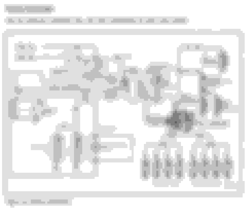
GP Controller Schematic and first page of Diagnostics/Testing
GP Controller Schematic and first page of Diagnostics/Testing
I'm too worn out to discuss this.
1) Schematic, self explanatory. This is not the only schematic that apples to start/run/glow system.
NEXT:
FIRST PAGE of Glow Plug System diagnostic Procedure. NOTE the labels and wire colors for the 8 pins on the connector that connects the glow plug harness to the chassis harness. On the Left the Controller terminal wire colors.
First, my service manual is the 1991 ford truck shop manual volume 1 and 2. September 1990. TW-728
It applied to my previous '91 e250 4.9 gas van. then i found it also applies very well to my '88 e250 7.3 idi.
So I say my manual will apply to any 7.3 diesel idi from 1987 to 1991. I wasn't sure it would work but it's covered everything in my '88 and I could not find anything different between manual and van which surprised me as I expected differences. If anything there is the occasional lack of detailed info, or could use slightly more clarification on a procedure. only about 5% of the manual has this problem.
your schematic is similar to mine. But mine have slightly revised wiring details. Yes, I have yellow fuse link at the starter relay battery feed that goes to the glow plug controller. That yellow wire actually says fuse link. "The key switch" supplies 12v power to fuel shutoff solenoid, controller and temperature relay. The temperature relay supplies power to the cold start advance solenoid and High idle solenoid only. my schematic clarifies wires connected, yours look like wires cross but are actually connected. Cold start relay is on the front of engine and mine works perfectly reducing idle after warmup. Takes mine +/- 5 mins on a cold day.
There are fuse links of all types scattered around the wiring just like the manual refers in that section of the manual. There is a fuse link to the hood light, but that fuse link is burned out and broken off mine. That's what I mean by fuse links everywhere.
my words on controller operation are from the manual page 03-01D-16 Glow Plug Fast Start System , from 87 and newer. I can't copy all the words. It applies only to 7.3 IDI.
Sorry, i have the book and don't have the tools to scan it in right now. I keep it on the coffee table, it's my bible and I read through it over and over. It was new to me before I started reading it and now my cover pages are completely wrinkled from over use.
from the manual: 03-01D-17
CAUTION: Never bypass the power relay of the glow plug system. Constant battery current(12 Volts) to glow plugs will cause them to overheat and fail, possibly resulting in severe engine damage.
That is because the controller has a high current resistor(that big wavy metal strip) that drops the voltage to 6 volts as proper glow plug operation but needs 8 glow plugs operating as a load. If glow plugs burn out, the controller detects this and cycles the glow plugs off sooner to prevent too much current from going through fewer glow plugs.
the top schematic is actually a wiring diagram, and shows no connection, of the controller, to a temperature control device. the bottom diagram is showing two 10 GA wires providing power to the relay thru fuseible links for the high current side of glow system, with a temperature sensor controlled ground, at controller, this is NOT CORRECT for engines with solid state controller's. Engines equipped with solid state controller's, need no information from engine sensors. ALL glow plug temperature measurements are resistance based, thru feed back from the 8 glow plugs, bad connections or faulty glow plugs, will shorten the heating cycle, as the measurement is based on the sum of the system. the time of after glow is based on the same measurement, the system shuts off after approximately 120 seconds, and only resets if power is removed. the 6.9 engine systems used analog sensors to control the glows these were problematic as under hood temperatures varied in different regions of the country, so hard starting was a problem.
Well I clean the ground for the controller, (had lots of paint on it from when I painted this engine), and now it's even worst.
It was around 34*F today when I started the truck, I counted on my digital watch timer, glow plugs stayed on for 24 seconds!
That's even longer than before.
Looks like this controller is coming off otherwise it's going to keep melting my plugs.
On a positive note, you'll never see another IDI start this quick in cold weather LOL
Fixstuff:
Thanks for the diagrams! I'll be able to wire up and get my Wait to Start light to work. Hasn't worked since swapping the Diesel in this F150 as the plug in the dash doesn't match the Diesel bezel I put in it's place. Just wait till I hear the relay click before I crank.
I just cut all my gp connectors off and put new bullet connectors all originals were brittle and the wiring was falling off posts. You have to remember resistance is important. Bad connections through wiring make glow plug draw harder and intermittent.
Check CDR. Blow by oil could damage rear gps. I know a clogged cdr we'll collect in #8 cylinder.
CDR stays open 99% of the time anyway. Only shuts during periods of high vacuum(wot with restricted intake). You *will* have lots of blowby no matter what. On a NA engine, it goes to #7/#8 more than others, on a turbo motor, it gets pulled through the turbo and mostly evenly distributed.
Originally Posted by swhitney133
I just cut all my gp connectors off and put new bullet connectors all originals were brittle and the wiring was falling off posts. You have to remember resistance is important. Bad connections through wiring make glow plug draw harder and intermittent.
Um... yes, but:
Crummy connections increase resistance. Increased resistance results in lower current flow. The controller sees increased resistance as increased temperature of the glow plugs, and turns them off sooner.
So bad connections = glow plug doesn't get hot enough, not the other way around.
...That being said, the opposite might do it. Check for a short from the glow plug wire to ground directly. That would /lower/ the resistance, which would make it stay on longer.
 02-16-2017, 05:29 PM