When you click on links to various merchants on this site and make a purchase, this can result in this site earning a commission. Affiliate programs and affiliations include, but are not limited to, the eBay Partner Network.
what is the cdr and what does it do and / where is it located ..
The CDR valve is very similar to a PCV valve on gas engine vehicles..
This Valve maintains proper crankcase pressure.
The CDR allows consumption and burn off of crankcase blowby while also regulating the pressure to prevent oil consumtion in the intake system ..
and to prevent oil and headgasket leaks caused as a result of this excessive buildup of pressure ..
ford classifies CDR clean out and service as a normal maintenance item though it rarely if ever gets done ..
if the valve diagphram fails or won't seat and excessive oil is drawn into the intake, it can collect from gravitational force and gravitate toward the rear cylinders 7 +8 ..
this oil is heavier than diesel oil and can cause excessive pressure buildup in these cylinders leading to 'lift' failure commonly seen as weeping of oil - diesel - or coolant from the back of the heads .. or outright head gasket failure ..
though many idi engines are driven their lifetimes without service .. i will leave it to you to decide if this is necissary .. and only show you how to service it if you are so inclined .. ford recommended it every other oil change .. but .. once in awhile will suffice ..
the CDR is the 'tuna can' on the back of the intake manifold ..
removal is by 1/2 inch socket on the 2 bolts on either side of the CDR ..
then push the valve straight back toward the fire wall .. to free it of the gasket holding it into the intake manifold ..
then move it side to side while pulling it up and out .. there is a grommet tube that will usually come up and out also .. though it may stay in the pan .. either way is okay .. it presses in on the bottom and on top there is an o-ring ..
this time my grommet tube did come out with the CDR ..
be mindful not to allow the mouse nest - acorns - old auto parts - to fall down into the pan hole ..
do not attempt to clean with the grommet out of this hole ..
clearly my CDR is too dirty and is allowing excessive oil into my intake ..
there is enough oil in the intake side to have it pool and take a nice reflective picture ..
my CDR is still good - we will test it in a minute - but it's too fouled up to properly function ..
first bunch up a grocery bag or some other device to use as a hole plug ..
we want to blast off the crunchy debris from off the outside of the CDR before internally cleaning and testing it ..
do not clean the front side too much with ultra hard solvent .. just mainly this side with the hole plugged and the bottom grommet downward .. there is a rubber diaphram inside that operates the valve and we don't want to get this super harsh solvent on it ..
once the hole is plugged spray it down with brake parts cleaner or carb cleaner ..
if you don't you may introduce crunchy dirt to the inside during the soaking process next ..
one .. put a gasket over that body lip ontop of the core support area ..
it's always a pain leaning into the engine bay because this thin sheet metal likes to nearly cut me .. i have a shorter radiator off a 460 installed so now this edge is more pronounced than ever ..
gonna cut a gasket to cover it for more comfortable workings underhood ..
and task number #2 is to clean off and paint the lid of the air cleaner ..
this had gotten rusty as a result of rainwater seeping in from the hood cowl area for years through an old cracked busted up gasket ..
well a few weeks ago i replaced this cowl seal .. and now that it's leak free it's time to give that ol' lid a facelift now that she's gonna remain clean and dry ..
shake it out and let it sit in the sun a little while ..
/caution/ i use a hair dryer after it's mostly dry to finish the job /warning/ gasoline vapor flammable / explosion death / do not try this at home .. but let it mostly dry out .
now to test it .. hold it just as pictured (in the last photo shown in the post above) - with your thumb extending to just past the end of the internal tube - make your thumb an airtight seal - and suck at the end with the o-ring where it affixes to the grommet tube ..
if the diaphragm is working properly - you should feel the valve plate move forward and press into the end of your thumb ..
this operation should be smooth and not leak down ..
does it work ? good .. i hope so ..
now .. we have to get the rest of the gasoline out of there .. because if we don't it'll sit against that rubber gasket and eat it out .. destroying the CDR ..
with your thumb still sealing the front tube hole .. point the front tube hole straight up .. and repeat the sucking action several times .. look at the small relief hole on the back side of the CDR .. this has to point straight down ..
as you move this valve up and down the gasoline trapped behind the backside of the diaphragm will blow out of this relief hole .. repeat moving the valve until no more fluid comes out then it is dry inside .. well dry enough .. the gasoline residuals will evaporate out quickly ..
now .. this step is optional ..
i want to keep that rubber diaphragm supple and free moving and free of dry rot and cracking ..
so i use rubber/vinyl conditioner ..
note this is not armorall .. armorall sits on the surface .. the product i use soaks into and conditions rubber and vinyl preserving it's elasticity and keeping it supple and preventing cracking from drying out ..
meguires 40 is the conditioner i use .. it's hard to find .. the only place that carries it near me is northern tool and it's about 10$ a bottle .. i use it on dash and interior parts and rubber door gaskets and the like .. o-rings .. and in cases like this rubber diaphragms .. i wouldn't bother using cheap armorall as it's not likely to help and could actually cause some damage down the road .. i would use M40 or nothing at all .. but that's me .. do what you want .
i plug the front hole and then spray a few drops covering the backside relief hole so that when i suck the valve closed it draws the rubber conditioner into this small hole .. and repeat about 5x ..
then spray conditioner 5x into the bottom hole where the grommet tube goes ..
then turn it up and down and around to get the conditioner all over the rubber inside of there .. pull the valve closed a few times and remark the smooth operation of the cleaned and conditioned CDR ..
turn it up again like with the gasoline and again operate the valve to push out any excess M40 from the backside relief hole ..
Hello, Leroy!
The best part about your instructions, (aside from your helper who was monitoring the area around your truck), is the instruction on HOW TO TEST the CDR, with a clear photo of how to hold it, which is the last photo in the post you made previous to the instruction.
You could make that more clear by editing the following line and adding the part that I put (in parentheses):
>now to test it .. hold it just as pictured (in the last photo shown in the post above) - with your thumb extending to just past the end of the internal tube -<
Or to that effect. It took me awhile to figure out what 'as pictured' you were referring to because the 'picture' isn't in the same post or below it.
Before servicing my CDR last summer I had researched, read and viewed essentially everything on the web about servicing the CDR. Exactly how to test it was still confusing and unclear. Your simple instruction with the photo makes it very clear so you get an 'A' on that! I'm glad you posted this
I have a few helpful things that I can add, with photos, that I will put below your quoted instruction:
Originally Posted by Leroy Unlisted
...
>snip<
...now to test it .. hold it just as pictured - with your thumb extending to just past the end of the internal tube - make your thumb an airtight seal - and suck at the end with the o-ring where it affixes to the grommet tube ..
if the diaphragm is working properly - you should feel the valve plate move forward and press into the end of your thumb ..
this operation should be smooth and not leak down
...does it work ? good .. i hope so ..
now .. we have to get the rest of the gasoline out of there .. because if we don't it'll sit against that rubber gasket and eat it out .. destroying the CDR ...
>snip<
FIRST, the Service Manuals state to cover the intake before proceeding. I used a plastic bag.
My CDR was very difficult to remove (for reasons shown further below). I could not simply push it back a little bit and pull it up and out. Being in an awkward/uncomfortable position made it worse. I often have to use a two or 3 step utility ladder or stool to work in the engine compartment. Something to use as a pillow on the front or side is also helpful.
On my CDR the down tube had been sealed into the valley pan grommet with Black RTV Sealant which made it difficult to pull out.
The photo illustrates how I got the CDR out in case yours does not come out easily. SEE the instruction below the photo:
I used the rubber strap on a strap wrench to protect the gasket between the CDR and the intake or whatever else might have been under it since I hadn't done this job before but the protection of the rubber strap isnot necessary. A much better/easier method is to use some wire in place of the rubber strap in the photo... baling wire, electrical wire, a long zip-tie, twine, steel coat hanger or whatever. Thread the wire under the CDR, bring it to the top and twist it/tie it together.
NEXT, use a 2x4 wood block set on it's side across the intake. The height of the 2x4 block set on it's side will be about 3-5/8 inches (92mm). Grab the wire with a 'channel lock' style pliers or other adequate tool, bar, etc. and pry against the wood block (as a fulcrum point) to pull the CDR straight up and out. I had to jerk it loose by banging the handles of the pliers (by hand) onto the wood block and after about 4 times it came lose and out.
The down tube on my CDR is different than most, it is a clamped on, stiff rubber hose with a nylon fitting on the end which goes through the valley pan grommet as you will see in one of the following photos:
Here is the nylon fitting on the down tube, showing the old Black RTV sealant, dirt, oil, etc., before cleaning:
The next photo shows the CDR assembly after it has been cleaned. The nylon fitting at the bottom appears to be a simple hose connector (splice connector) for connecting two hoses of the same Inside Diameter.
Notice the THICK PLASTIC GASKET to the left. That goes between the CDR and the intake. More comments below the photo: CLEAN CDR AND INTAKE GASKET
NOTE: The gasket seems to be made of thick plastic and quite hard. It is approximately the same thickness as the length of the tube or slightly more. From memory that is about 1/4 inch thick. Possibly it was softer when it was new. It has a slight ridge around the center hole where it was compressed up tight against the intake hole. NOTE that THE INTAKE SIDE OF THIS GASKET IS NOT FLAT. It has a slight curve to conform to the curvature of the cylindrical shaped intake, so when reinstalling an old gasket like this one make sure that the curve in the gasket is matched to the curvature of the intake instead of being 90 degrees off for example - where the gasket would then not seat properly on the intake. That could result in air leaks and allow dirt to get into the intake.
NEXT notice the down tube, ear clamps(aka crimp clamps) and nylon fitting on my CDR. I had intended to replace the rubber hose (which is very stiff) with a standard metal tube but after loosening the upper 'crimp clamp' I couldn't get the hose off or even turn it. I decided not to apply any more force to get it off and I was certain that it is in good enough condition to re-use as it is.
After compete examination and much thought I concluded that using the hose, nylon hose connector fitting and crimp clamps is actually a very good way to install a CDR. I have several reasons to suspect that this was done by a professional diesel service shop and not by a DIY previous owner. It is a very adequate alternative to the original tube assembly.
However, I would recommend not using standard screw type hose clamps. Those are most often cheap junk. Although this is not a critical application, those screw type clamps don't hold as evenly or as well, they can come lose during constant vibrations, especially after they get hot and the metal expands, they are intrusive and take up more space in such a tight area.
Instead, my preference is to use a narrow style of crimp clamp similar to those in the photo. These were used by manufacturers for as long as I can remember because they are inexpensive, quick and easy to install, clamp evenly and hold well under all anticipated conditions and last a long time. Various styles of crimp clamps are often used on vehicles in Europe and on small aircraft engines for fuel lines (because it clamps evenly and holds very well under vibration and heat conditions). A similar style is used on CV Joint Boots. OR you could use a double spring clamp which looks similar to a thick spring and works the same way as the clamps that go on return fuel lines. Most of the crimp style clamps that I have seen can be crimped with an end cutter (aka nail cutter) if you don't have a crimping tool. If all you can get are screw type hose clamps those should work fine for this application.
I couldn't see the grommet in the valley pan very well, even with a mirror and LED flashlight. I didn't want to pull it out, mainly because it was securely installed into the valley pan and I didn't have one to replace it with. I've read where others have had problems finding a new grommet that will fit so I left it in. I was able to clean it off well with a cotton cloth rag and solvent. When I re-installed the CDR I used a bead of Black RTV Sealant around the inside lip of the Nylon fitting and I applied a little bit more around the outside edge and smoothed it with a finger. (I have long fingers). I didn't want it to ever leak.
Next time I do this, I will have to pop it out the same way, using leverage against a block of wood and hopefully I'll have all new parts to install.
just for anyone reading this as an instructional .. there's not supposed to be rtv on the o-ring or grommet ..
the gaskets themselves make the seal .. any extra could possibly fall off into the valley pan and clog up one of the oiling galleys ..
also today .. it was bugging me - that fresh clean looking air filter lid was making the bottom of the air cleaner look crummy by comparison ..
with the old gunk of a long fallen off motorcraft sticker residuals and that long ago obsolete 'do not use ether start because this engine equipped with glow plugs' sticker ..
so i decided to take it off also and paint it to match ..
i wasn't gonna mention it but i guess i will take a picture and add it late r..
i looked at my old air filter and it was saturated with oil from that dirty CDR .. so i also cleaned this too .. washing it in dish soap and rinsing it 5x in clean water .. came out nice .. but was tough to dry ..
i gave up on the hair dryer and vacuum and wen't over to my home heat pump .. a few zip screws later i had opened the output duct and stuffed it in there for half an hour .. that did the trick .. nearly fully dry except a few little spots .. and most importantly not oily restricting the airflow ..
the prefilter poly fill stretched out too much after cleaning .. but i had 2 large elastic cargo straps that fit it perfectly and holds it right on the edge ..
painted up the base .. put vaseline around the intake collar .. put the base down .. vasolined top and bottom edges of the now clean and strapped air filter .. put some M40 all over the lid rope seal on the bottom of the lid rejuvenating - and making that air tight .. and cinched it all down again ..
all the intake side is clean now ..
she's noticeably happy again breathing fresh air .. my exhaust had - of late .. been kinda sooty .. but now with it cleaned and breathing good the exhaust is very clean .. not smoky or sooty at all .. throttle was snappier and sounded better overall ..
it was getting dark and i didn't want to run it through it's full paces until the filter fully dries overnight .. but i expect she'll pull a bit harder .. run a little cleaner .. and probably see improved fuel economy ..
all in well worth the effort .. okay .. bye for now .
If I may so bold, but I'd like to post some pictures of the CDR locations on the IDI van, for future reference.
Non-Turbo IDI Vans:
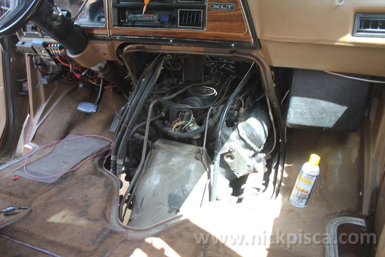
On a stock non-turbo van, the CDR is located under the air filter housing, just like on the trucks. In the image below, you can see the "tuna can" at the back of the air intake manifold, next to glowplug electronics.
Hypermax Turbo IDI Vans:
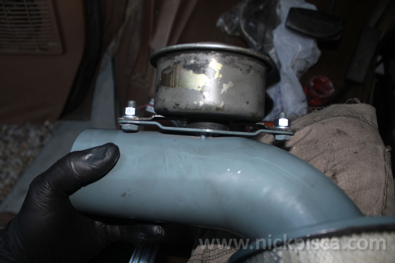
The turbo kits have moved the CDR to recirculate crankcase gasses into their turbo air filter housing tubes. The CDR is mounted to the tube like this:
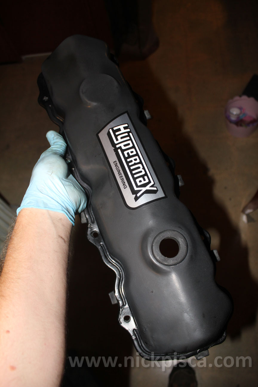
The Hypermax kit requires the drilling of the driver's side valve cover, and installation of a grommet and adapter to connect the engine to the CDR.
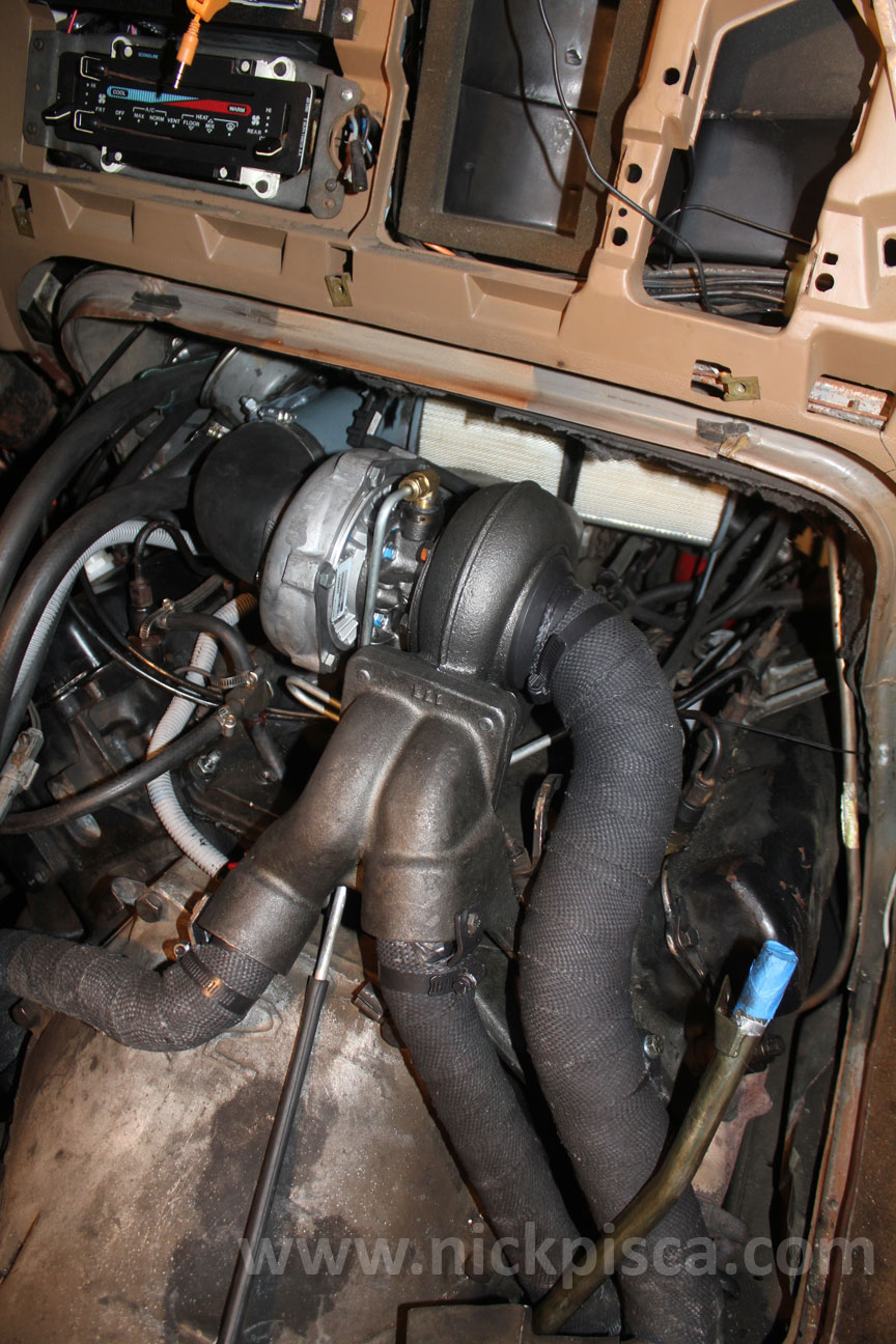
Once installed, the Hypermax CDR assy should look like this: (you can see the "tuna can" on the upper left of the engine bay)
Banks Turbo IDI Vans:
Just like the Hypermax kit, the CDR is mounted to the air inlet tube between the air filter and turbo.
Here is the location of the CDR on the Banks Van Turbo, along with the 1" diameter breather hose routed up to the tee on the oil fill on the gear housing:
Instead of venting through the valve cover, it retrieves gasses from the gear housing.
>snip<
ford classifies CDR clean out and service as a normal maintenance item though it rarely if ever gets done .. >snip<
YIKES! I have this service item *!!!MARKED!!!* as *!!!SERVICE CDR!!!* *!!!EXTREMELY IMPORTANT!!!* as the name of 3 different folders in 3 different places and additionally on one of the documents !!!OR ELSE - UH-OH!
***!!! BLOWN HEAD GASKET !!!***
Yet STILL I kept forgetting about it until one day I decided to do it.
if the valve diaphragm fails or won't seat and excessive oil is drawn into the intake, it can collect from gravitational force and gravitate toward the rear cylinders 7 +8 ..
this oil is heavier than diesel oil and can cause excessive pressure buildup in these cylinders leading to 'lift' failure commonly seen as weeping of oil - diesel - or coolant from the back of the heads .. or outright head gasket failure ..
Based on a post long ago (which I copied for my reference folders) by a user named PLC7.3, (I don't know the title or location of the original topic), I learned that the oil has a higher BTU output than diesel fuel. Thus it will burn hotter. I perceive that to mean much hotter and below is part of what PLC7.3 wrote. I read quite a few of PLC7.3's posts and I trusted that he knew what he was talking about. I'm going to underline with bold letter emphases a few things in this partial copy of his post:
Originally posted by PLC7.3;
>snip<
All 6.9L and 7.3L diesel engines are equipped with a CDR (Crankcase Depression Regulator) valve. Even the new 7.3L Power Stroke is also equipped with the same valve. The CDR valve is one of the leading causes of head gasket failure in these engines. The CDR valve is responsible for controlling the pressure/vacuum in the engine crankcase, and separating the oil mist from the air and returning the oil to the crankcase. The CDR valve should be serviced every second oil change or when signs listed below are seen.
When the CDR valve is not properly serviced, engine oil enters the air intake and is drawn into the engine. The diesel engine will burn this oil as fuel, however, it is heavier and thicker than diesel fuel and, having greater BTU output, causes excessive heat in the cylinder. Due to the intake manifold design, most of the oil will migrate to #7 and #8 cylinders; the last two cylinders in the rear by the firewall. The increased temperature here will cause the cylinder head to lift off the gasket and allow water or oil to leak out the back of the cylinder head where it meets the block. >snip<
To ME that means "blown head gasket" which will need to be replaced AND that there is a clear risk of blowing a head gasket by ignoring CDR maintenance or replacement. Especially if the truck is worked hard such as towing up long grades. Without a working Exhaust Gas Temperature (EGT) Gauge one would be unlikely to detect such a problem.
I don't care how many might state or think that a truck ran OK for 100k, 200k or 300k miles without servicing or replacing the CDR, (if anyone would claim that) but I for ONE will never take that risk.
A blown head gasket would SINK my poor little boat. At my age and with very significant chronic pain issues and very low income that would be devastating. I COULD do it. I'd have to save for 2 months just to afford a gasket kit, rent an engine hoist to lift the heads or pay someone else to lift them out and rent or find a place to do the work. It would take quite awhile before it was done.
I have to avoid mistakes and repairs like that and this is why I have to maintain my truck meticulously and mostly that means to do a very careful job and the best job that I can on everything I do to fix, repair and maintain this truck. Former professional mechanic friends have made fun of me (teased) for being slow and taking so much care toward 'perfection' in what I do. I think things through completely before I ever start, anticipating every possible problem and sometimes I come up with better ways to fix something but how long will my fixes last compared to their faster but somewhat careless approach? I won't have to look back when a repair prematurely fails because I didn't do a very careful job.
Anyhow the point of this post is to emphasize how important CDR maintenance is. Also for repairs and maintenance in general, to focus on doing everything correctly the first time and if you have the time and convenience do a nice clean job.
That being said, below is a link to a helpful article at the Diesel Hub on replacing or servicing the CDR valve. STILL, Leroy's instruction on testing the CDR with the photo is the clearest that I have seen.
(I hope you're instruction is correct, Leroy! I trust you). The only better way I can think of is to use a vacuum pump and gauge to test for a leak-down which would indicate if there is a very small leak through the diaphragm assembly. The 1987 Ford Service manuals do not describe a method to test the CDR but I am going to double/triple check that to be certain.
 02-10-2017, 08:20 PM