When you click on links to various merchants on this site and make a purchase, this can result in this site earning a commission. Affiliate programs and affiliations include, but are not limited to, the eBay Partner Network.
Tedster9 My same thoughts, wonder who got the best deal when it was all said and done with it going out the driveway.
Looking back on it Steve would you do it again tying up all your spare time for so long?
Orich
I'm like anyone else, I like money too. However, I'll be 50 this Friday. While I don't consider myself an old geezer (yet), I'm from the old school of a man's word and his handshake still means as much as any written agreement on some piece of paper.
I have way more time into all of this than the money made from it --if we were going on an hourly rate standard of charging for the job.
Dylan's a good guy and if not for him, I wouldn't have the truck I have now (which I bought from him 5 years ago). I'm not trying to get over on him or anyone else. Maybe I don't charge what I should but, I'm just looking to make some money towards my own Bumpside project and produce quality work for someone who was willing to give me that opportunity by earning it with their vehicle.
A person's price for work is not always based on what you can get out of the other guy for your own greedy benefit. It's more about a mutual trust that a person can get quality work at a more than fair price. They tell/show someone else about their experience and you get more business in the future, if you want it.
Very nicely put. You are correct, a shop isn't going to (generally) have near that much attention to detail. It's not that they can't but if someone wants that level of work the figures quoted might be low. The shops are always busy and need to stay that way. That's why, when I have someone do repair work and get the final bill, may not like it too much but I just gulp and pay it. Because I know what's involved.
This handshake business is good, and I subscribe to it as well just beware that there are people out there who make it their hobby to **** over guys like you on principle, whether on the business or customer side. I'll never fully understand why, jealousy or probably envy I guess. Excellence is something to be admired. Anyway thanks for taking the time to outline the work that you do with pics and commentary.
I understand what you're saying. However, I can't worry too much about it from the customer point of view, in regards to THEM thinking they're taking advantage of me. I have a full-time job that pays the bills. The sideline work is just some extra money to help with funding on my own project truck.
If the potential customer out there has the inclination they are taking advantage of someone else providing the service, that's on them. There's a nasty thing called "karma" and it will come back on you many times over to erode whatever savings (and much more) you think you duped the guy out of that was working for you. Conversely, it works the same with the opposite respect.
Some of the photos from the beginning and during the process of this conversion.
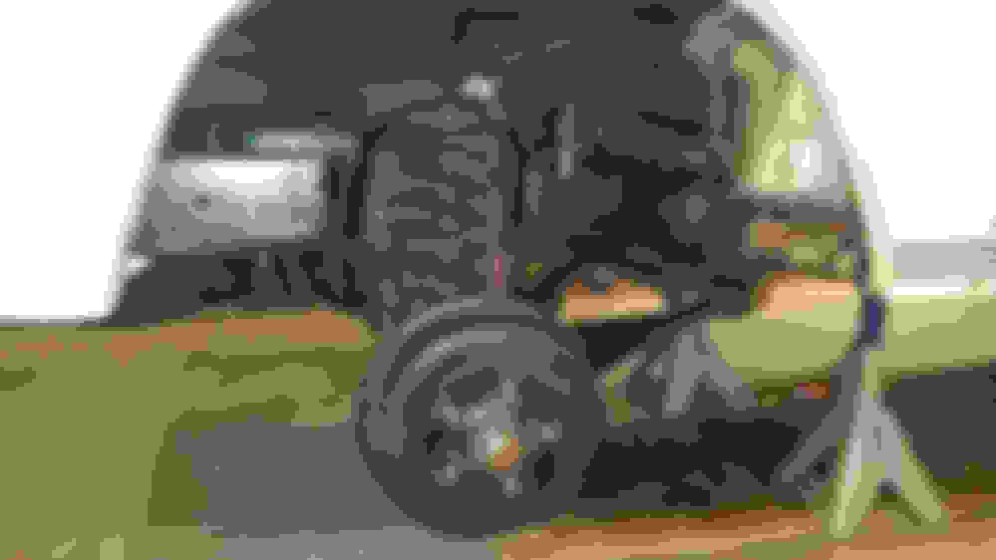
The foundation of the donor front discs/suspension, as I found them in the bone yard.
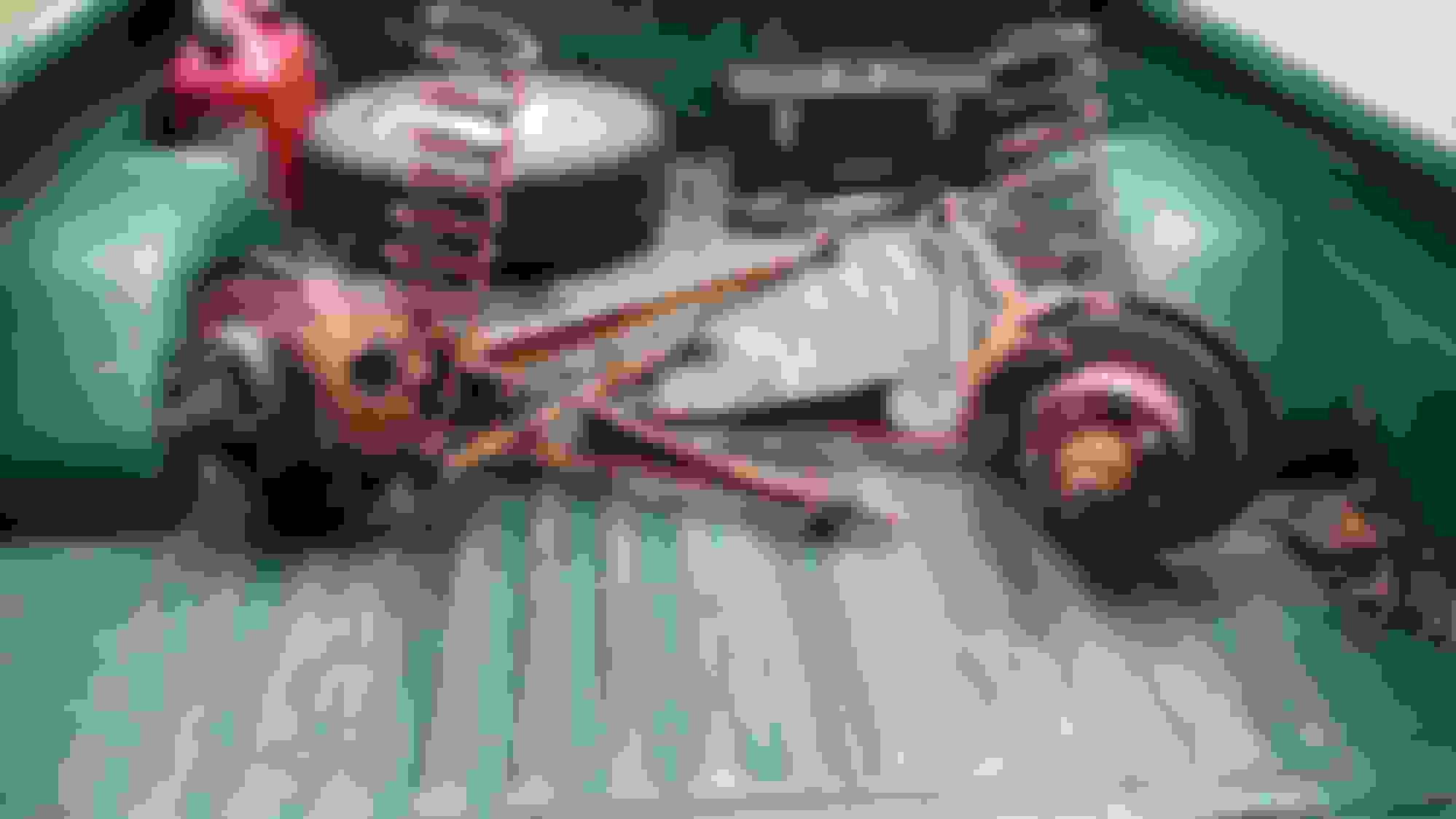
As I found the '75 discs/suspension parts on a frame with no body --sitting on the top of a pile of other frames with no bodies. ....I figured this would take maybe 2 hours total to pull. --it took 5 hours, since after I finally got the parts loose, I could not lift the frame off the suspension or roll the frame over. Yard owner finally brought the boom truck to the rescue.
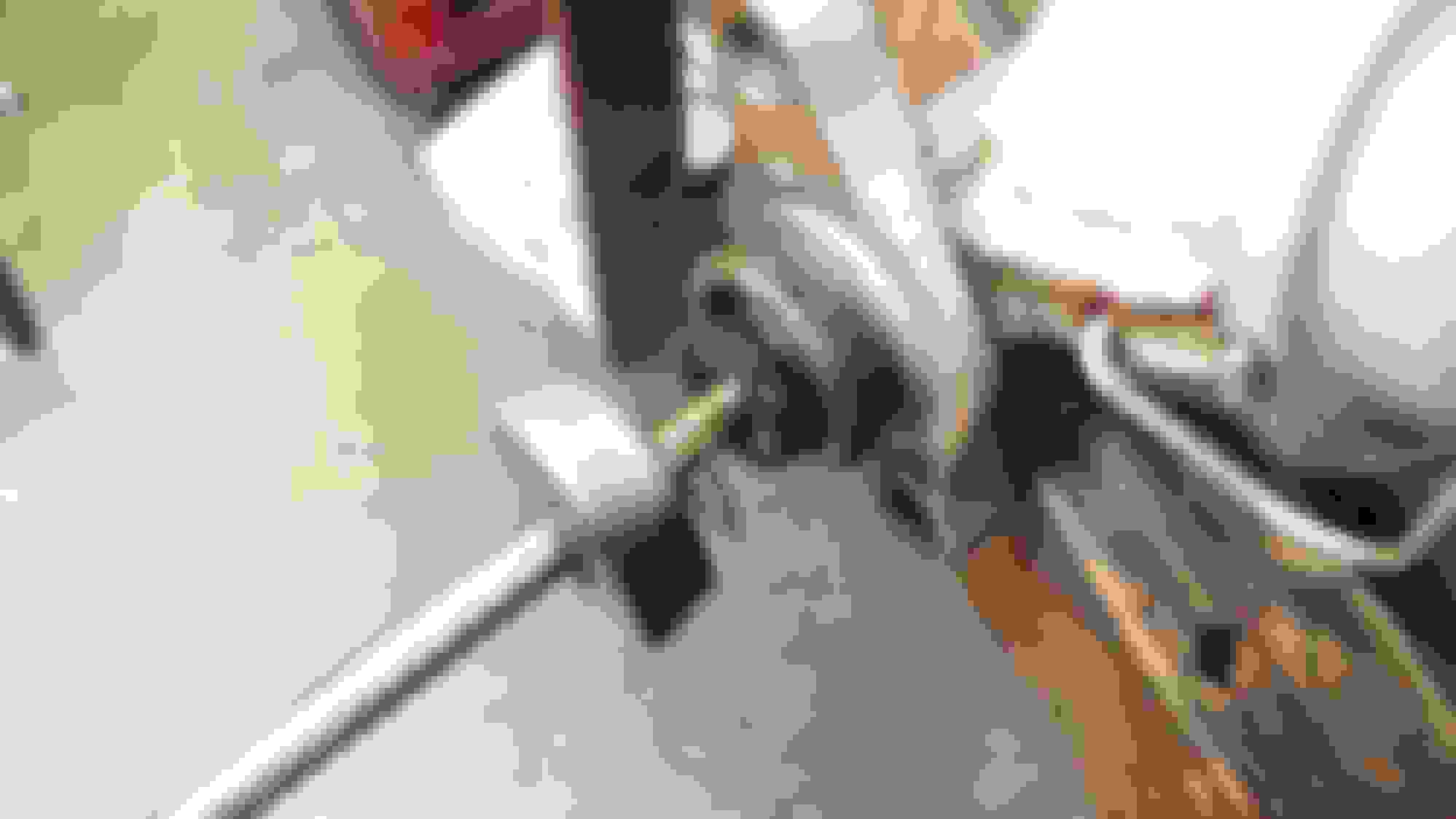
Parts loaded in the back of my '69 to bring them home and begin the process of teardown and clean up.
Right side mostly blown apart --had a casualty with the pipe wrench. Pays to have the right tool. When I did the conversion on my truck, I borrowed the needed 1-1/8" end wrench. Didn't have it this time. Went and bought the proper wrench after this failure mode occurance.
'75 I-beams had '74 date stamped radius arms and disc brake splash shields. This meant no notches in the forward ends of the radius arms for the locating pins on the sway bar endlink brackets I was going to install (for future addition of a '75-'79 F100-F350 factory front sway bar). Now what?
....mark the location of where the notch would need to be....
....put it in the Bridgeport mill at work and milled it out --this could be done at home with a 3/8" drill bit in a hand drill or in a drill press and with a cut-off wheel. If you have access to a mill though, it's much quicker.
That problem solved.
The inboard air intake scoop on the left side disc splash shield was severely bent inward and had a big chunk missing out of the stamping and, overall, the whole shield was warped (??).
Shield warpage corrected and the air scoop hammered and dollied back out --although I don't really know anything about body work techniques.
Mark section around the bad area to be cut out.
Cut out a patch piece from a left over remnant of a new '67 Mustang floor pan and weld it into the area where the original metal was missing from the shield.
Shield will live to carry on with duties again.
.....will continue with more transformational photos later. Getting very late now.
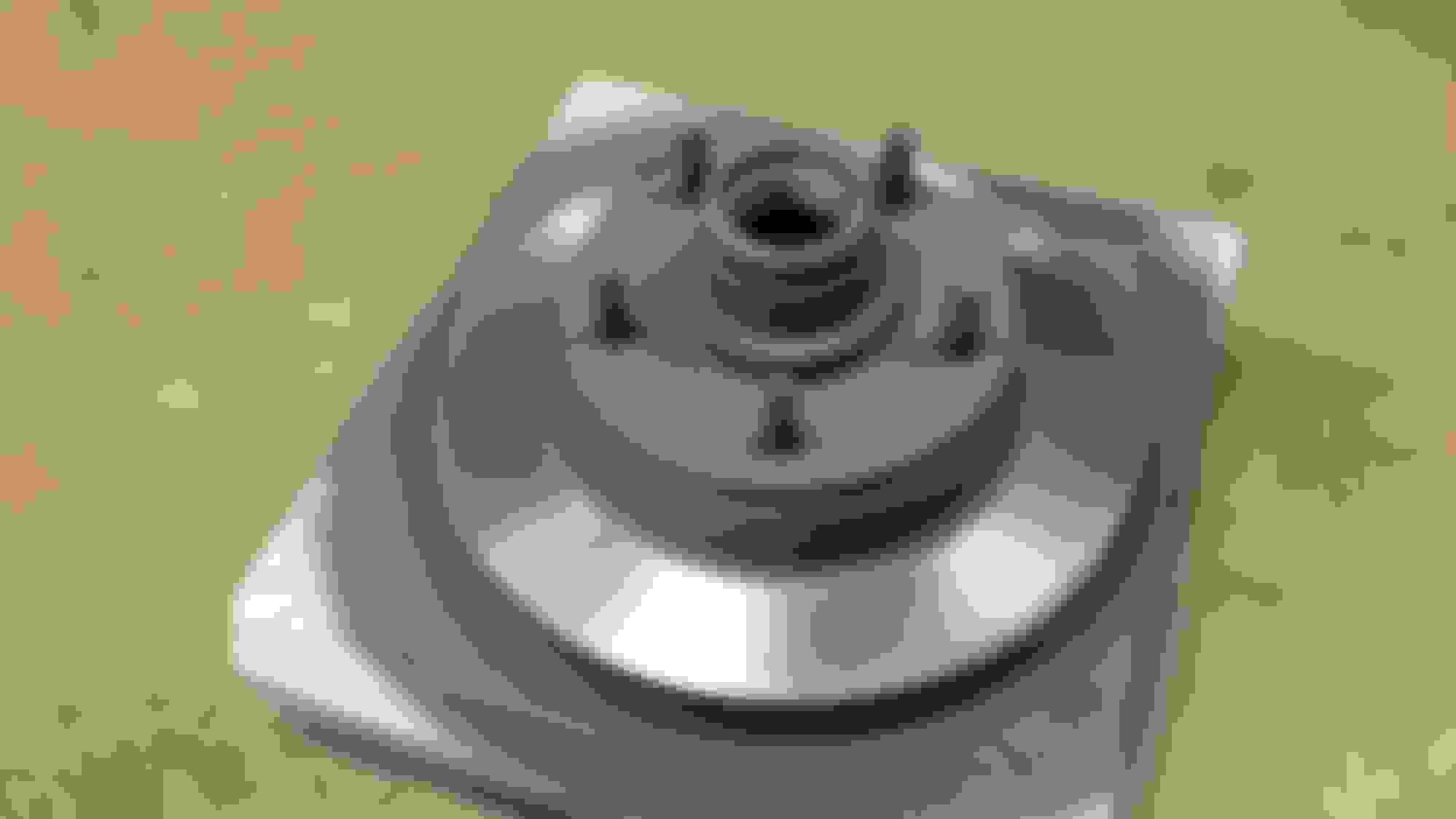
Old I-beam bushings being pressed out, new ones pressed in and masked off so beams can be primed and painted.
Made a tool in the lathe at work to install the bronze kingpin bushings with.
I-beam with new bushing installed didn't want to fit up inside the pivot bracket on the right side frame rail. Took a piece of 1/2"-13 all-thread, some flat washers, (2) 1/2"-13 nuts and spread the mount back out.
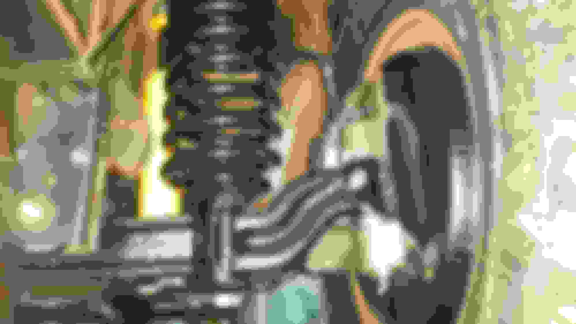
Right side components set into place. With the stiff new radius arm bushings, the threaded stud on the radius arm wouldn't stick through the mount far enough to be able to get the 3/4"-10 nut started. Hooked a come-a-long to the radius arm and the crossmember to pull the arm back into the mount far enough to get the nut started.
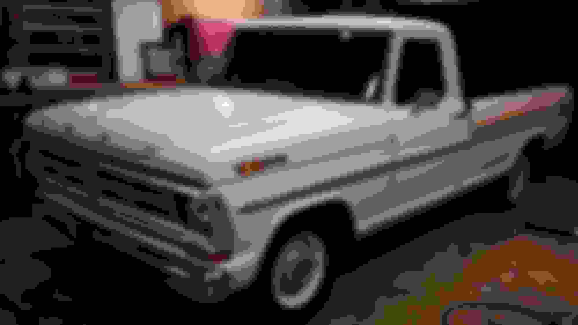
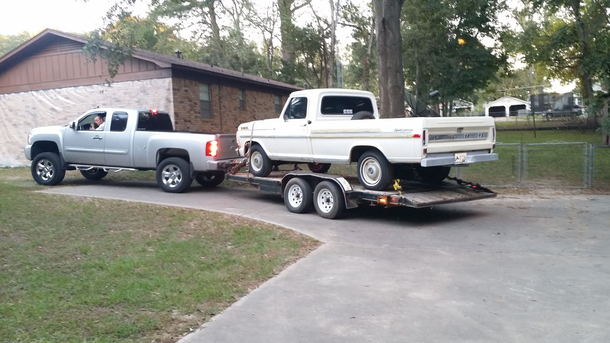
Yep. Good job as usual Steve. I caught that you have it ready for a front stabilizer bar. Just no bar yet. Are my eyes deceiving me? That silver tow rig looks like a Chebby with a Ford oval on the tail gate!
I did the same thing on the highboy's rear brake line. It was perfect until I made the very last bend....in the wrong direction. Doh!
I've been making brake lines and doing disc brake conversions for a good number of years now (mostly on vintage Mustangs, a few Chevys and now on a couple of Bumps). I've never had any formal instruction on how to bend or flare lines and I figured out how to do this on my own, simply by fooling with it. Even after years of doing this though, I do still mess up from time-to-time. Fortunately, brake tubing is fairly cheap. The biggest loss is just in the time put into it when something goes wrong and having to start over with another line.
One way to help keep from bending the tubing in the wrong direction is to take a Sharpie and scribe a very short line, parallel, along the length of the tubing, as an orientation mark. When you put the tubing into the bender to make the 1st bend, orient the mark towards the ceiling. You know this is up. Making the successive bends from there, you'll know which way is right, left, up, down or diagonal, based off that orientational reference mark.
Originally Posted by Tedster9
....Anyway thanks for taking the time to outline the work that you do with pics and commentary.
I realize many of my posts are long. After the '72 was loaded up on the trailer, Dylan and I were standing by the truck and talking. He said he learns more from watching than trying to just read about something. I told him I'm the same way. I'm a visual person. Most things --brake systems for example, can be very intricate in all the types and configurations of the individual parts needed to put together a functioning system. These details are important and a simple one or two line sentence just doesn't give all the pertinent details to a reader on the forum who's trying to figure out what's needed or what to do.
I try to explain the parts and procedures, along with included photos, to explain what it is I'm talking about in the text, so a person can put the text and photos together and better visualize and understand what it is I'm trying to convey through both.
Originally Posted by JEFFFAFA
Yep. Good job as usual Steve. I caught that you have it ready for a front stabilizer bar. Just no bar yet. Are my eyes deceiving me? That silver tow rig looks like a Chebby with a Ford oval on the tail gate!
Thanks, Jeff. The 'C-brackets' for the front sway bar was a spare set I had. Currently, we didn't have a '75-'79 F100-F350 sway bar assembly to put on but, NOW was the time to install the brackets, while the front suspension was being put on. I did NOT want to have to pull the 3/4"-10 x 6" bolts loose to install the brackets later, when a sway bar assembly is available. --going back and putting the C-brackets on later would have had a very high suckage factor associated to it. I didn't notice a blue oval on the '12 Chevy but, it may have been possible.
Dylan said after he did a few more things on the '72 to make it more road dependable, he was going to sell his '12 Chevy and use the '72 F100 as his daily driver. Not having the monthly notes on the Chevy would also free up more money each month to fund improvements on the Bumpside.
i'm glad guys like you post this kind of work, it's invaluable for guys like me who never owned these trucks before
Thanks, emeraldcoupe. I'm glad if my ramblings help you or anyone else looking at anything I have to say or show what I've done or, of what I'm in the process of doing, helps you/them with their own projects.
My dad had a '68 red/white short bed F100 Ranger he bought from my uncle around 1972 (I was 6 then). When my uncle had the '68 Ranger, he had converted the interior and exterior to '70 model Ranger trim. My dad sold that '68 in 1988, when I was 22. It was the first vehicle I learned to drive. As a kid, my dad showed me some basics of servicing the drum brakes and stuff like that but, we never did any sort of conversions or modifications on the Ranger.
Up until about 5 or 6 years ago, I really didn't have a lot of knowledge about the Bumpsides. The majority of what I know now (and still a LOT left to learn) has just come about in this relatively short time frame from MANY hours of reading, observing and from just fooling with my own '69 F100 project --and more recently on this '72 F100.
There are guys here with far greater skills and knowledge than what I have and I learn from things they are doing too. In spite of the fact that there's a plethora of information and knowledge here, I still find that I have to figure out many things on my own in coming up with solutions of how to correct problems, add components from later model Fords or, fabricate something that will accomplish what I'm trying to do.
The main thing is to be diligent in your research BEFORE doing any major changes, use common sense approaches to sorting out problems and things will usually turn out just fine when it's all done.
More behind the scenes stuff that led up to how the components were processed that are on the '72 now.
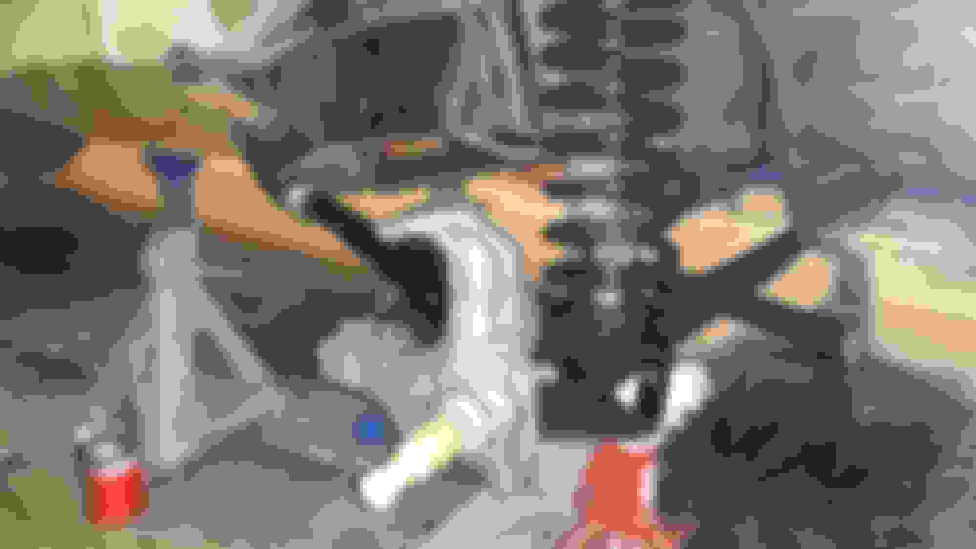
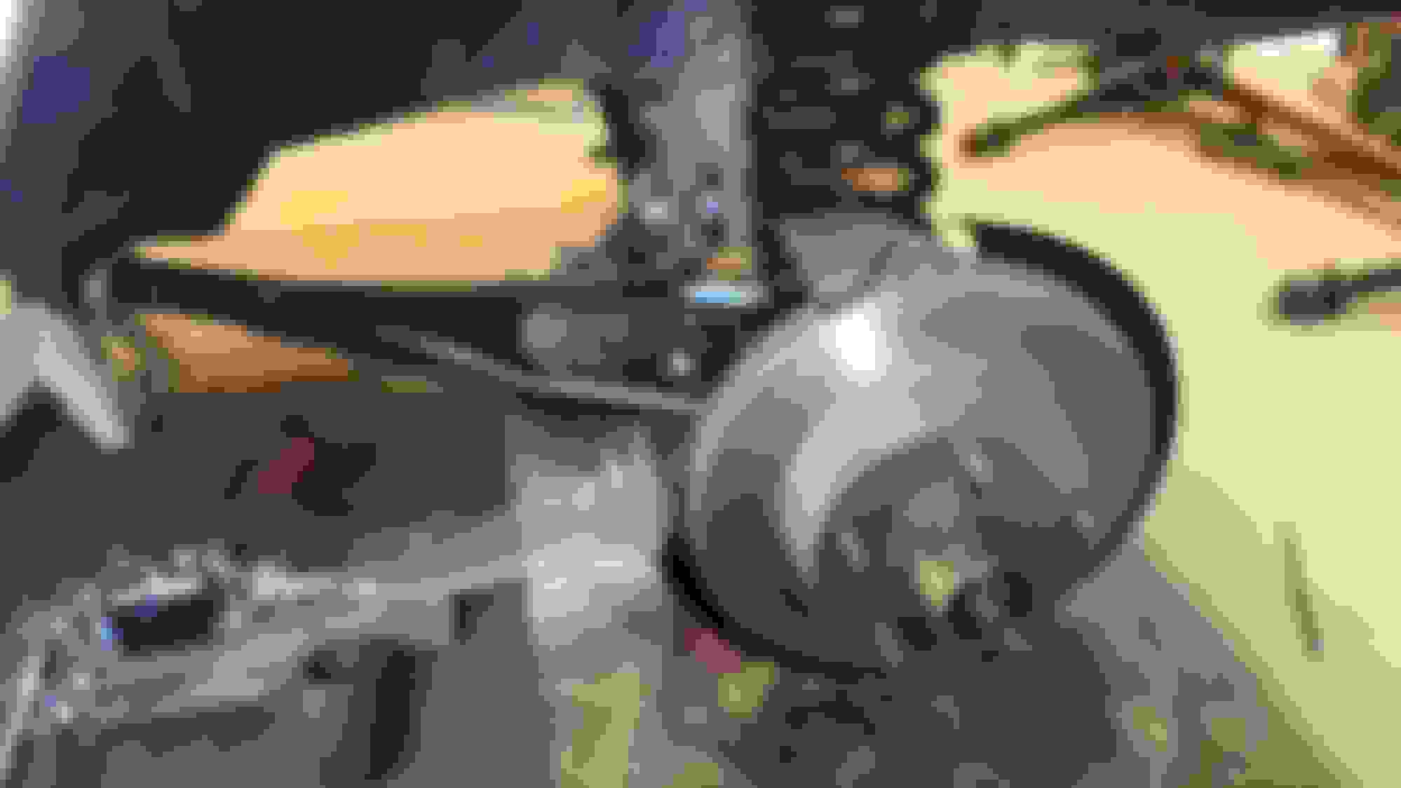
The night the '72 was delivered. I stayed up late that first (Friday) night, a few months back, in starting on getting things unhooked and unbolted, to get the drum brake front suspension assembly ready to be removed. I got up early the following Saturday morning and got the front suspension removed by around 7:30 a.m.
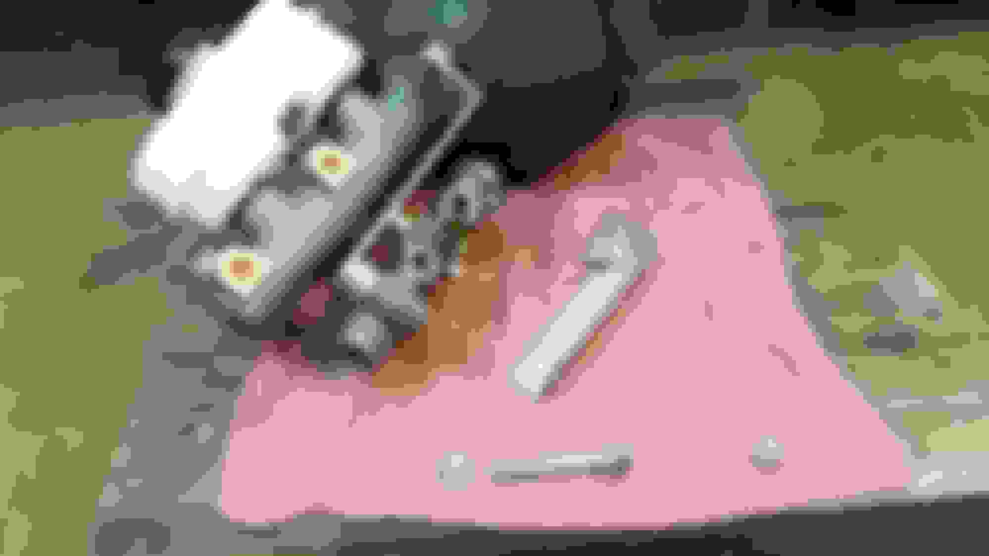
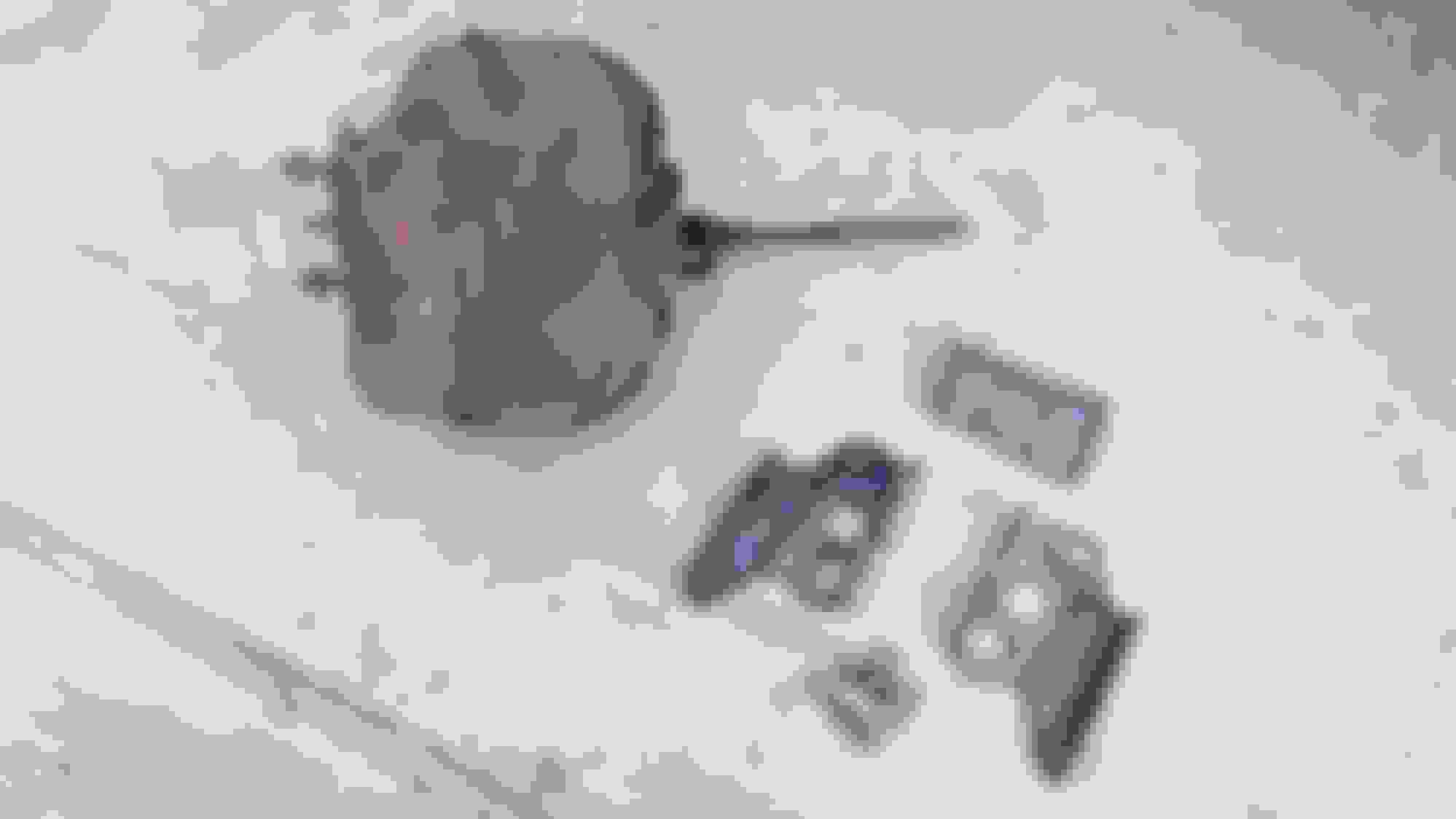
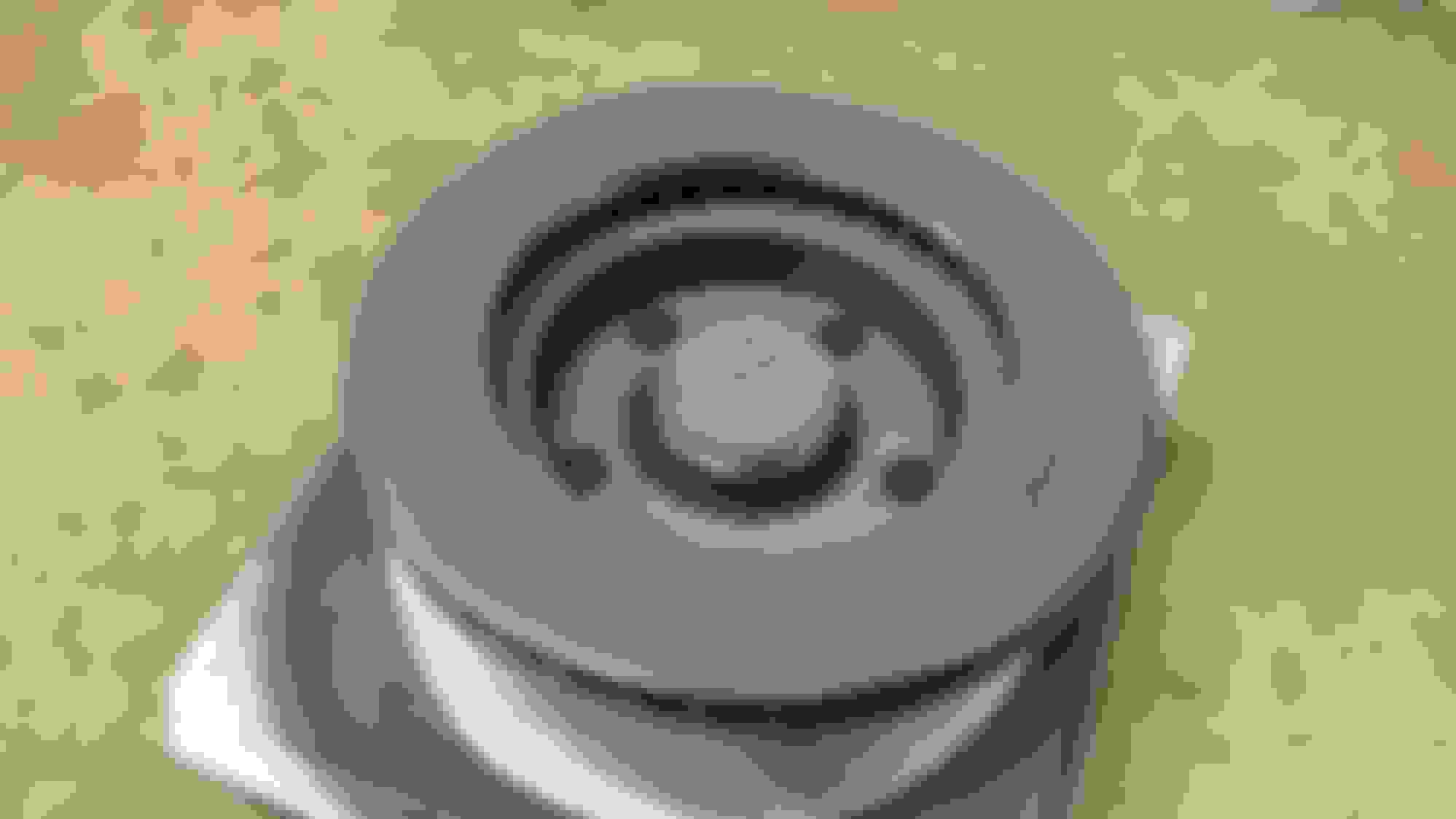
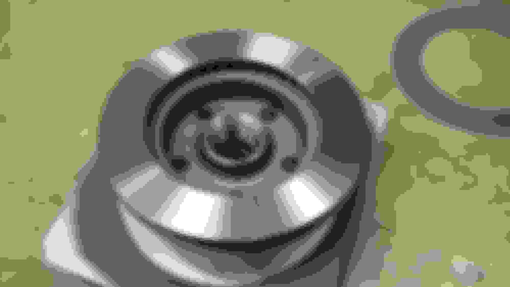
Some random parts at various stages I had degreased, bead blasted, primed and painted.
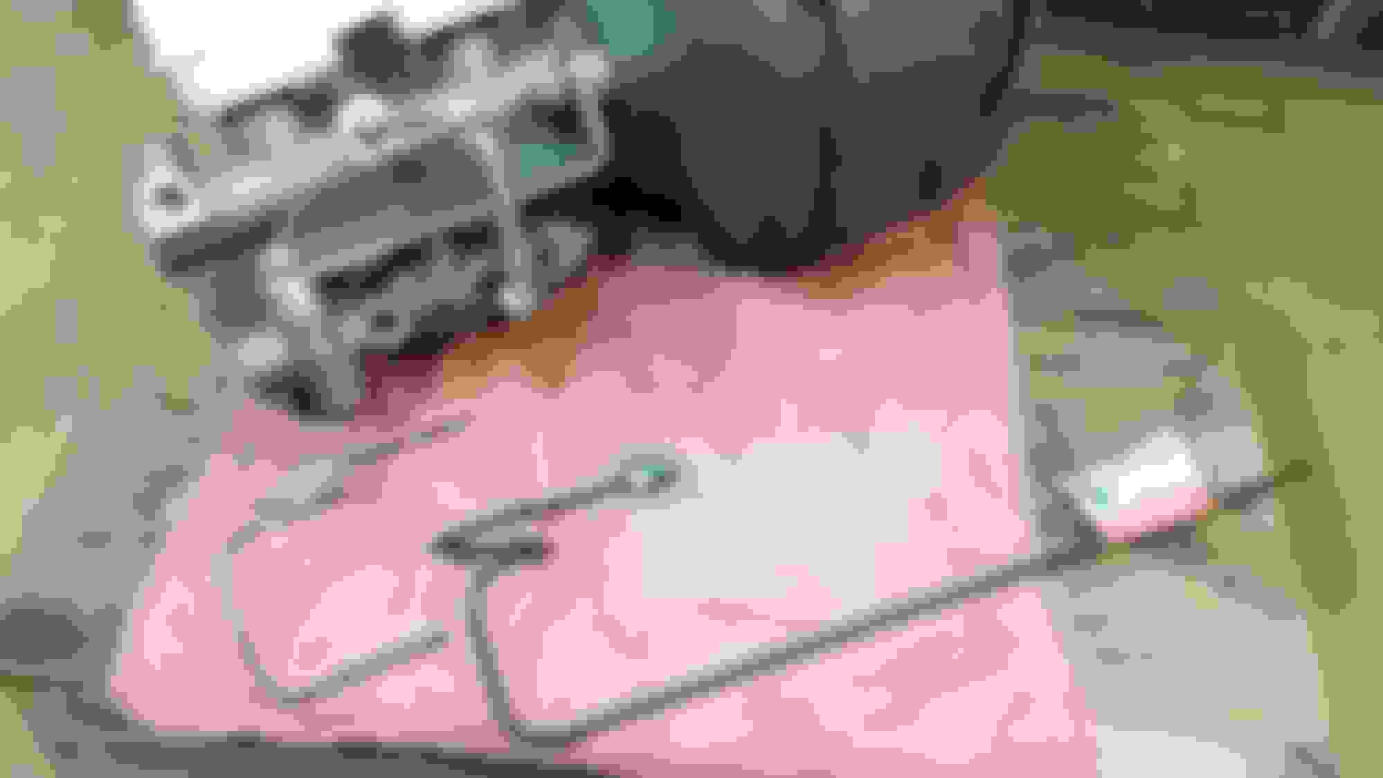
There was a long rubber fuel line going from the fuel pump to the carburetor. In the interest of safety, and while I was at it, I made a new 5/16" hard fuel line for the engine and pitched the rubber line.
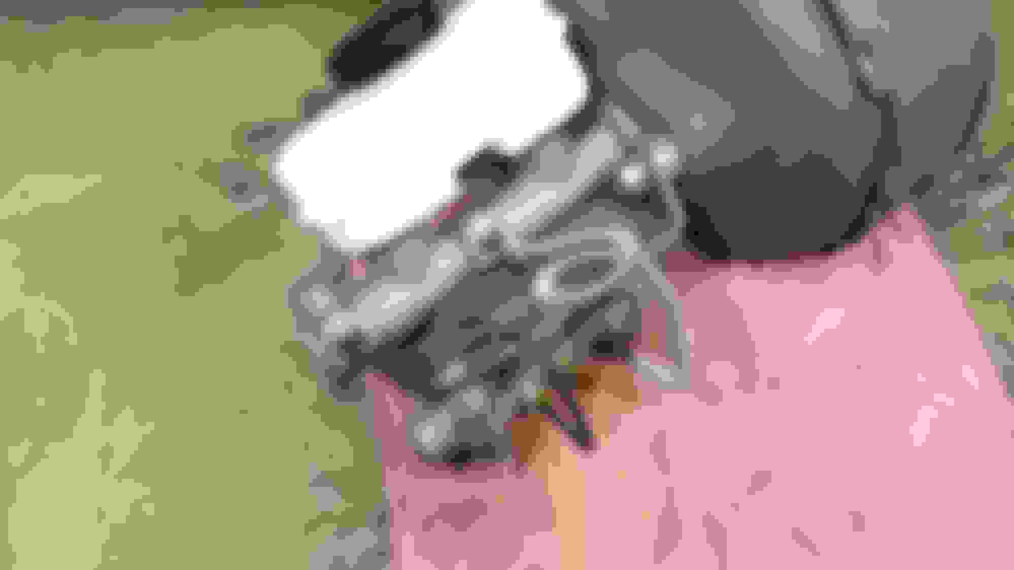
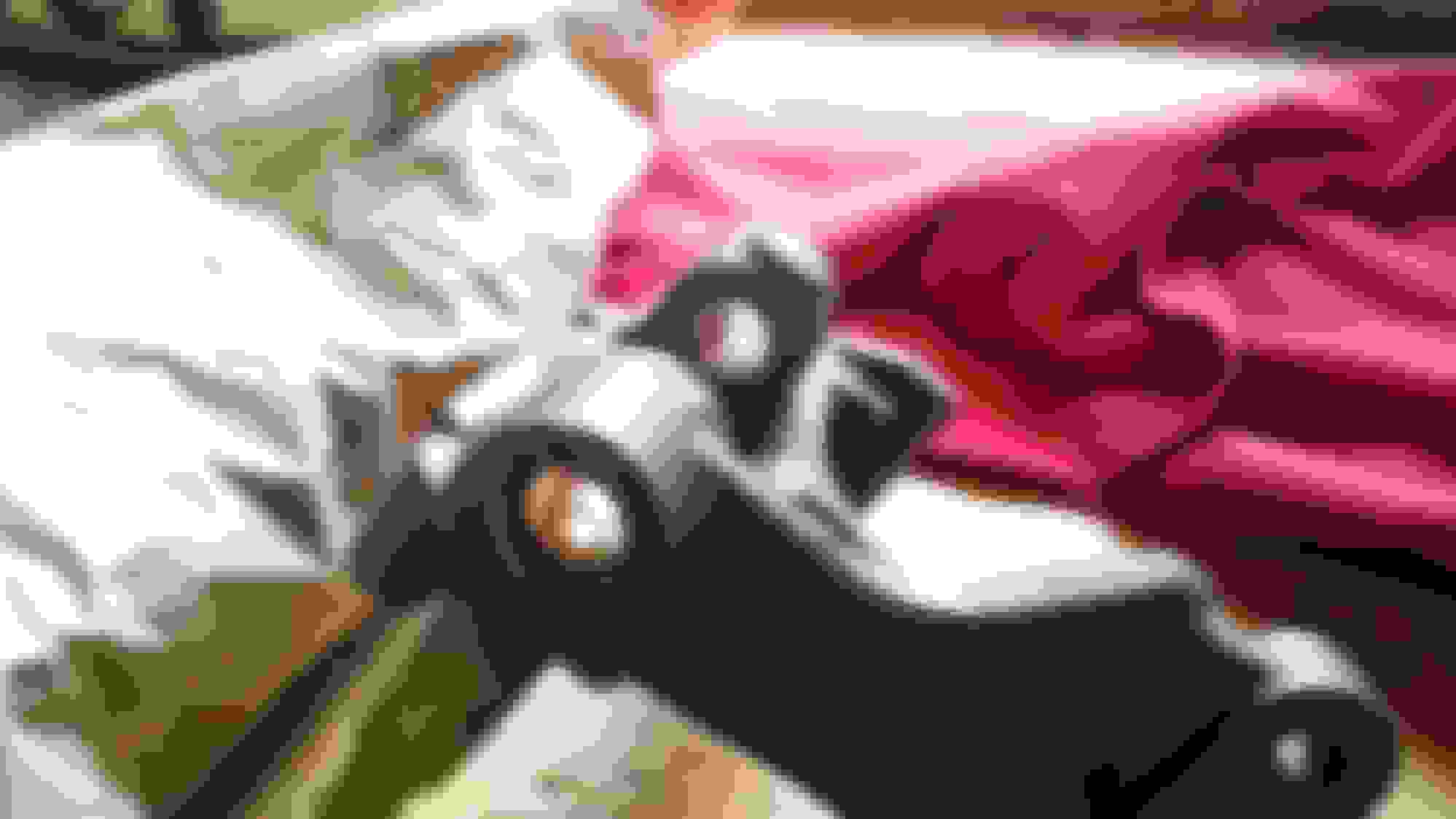
When I took the old cast iron MC off the firewall (truck originally had manual 4-wheel drums), I was looking to see why the MC was leaking out the back end.
I pulled the dust boot back and looked up inside it to find the primary piston retaining snap ring had popped out of the cylinder bore groove and was dangling off the input rod. This allowed the primary piston to protrude out of the MC bore to about the distance shown in this photo. This would explain why the red brake warning light on the dash was glowing. --a potentially very dangerous thing to have happen.
The old drum/drum pressure differential brake valve unhooked but still in its original location inside the left frame rail, directly behind the steering gear box.
It was removed and replaced by this disc/drum brake valve from an '82 Bullnose F150 donor truck --shown after I had bead blasted it and was waiting for the primer to dry.
The piece of scrap 1/8" thick aluminum plate that I cut out and made into the valve mounting bracket, which I relocated the brake valve to being mounted off the brake booster studs instead of inside the frame rail.
The cast iron brake valve weighs about 2 lbs --it actually weighs more than the unladened weight of the '95 Explorer MC.
Since the cast iron Kelsey-Hayes valve has a good bit of weight to it, I knew if it was hanging on the aluminum bracket, with an unsupported free-span (other than where it attached to the booster studs), the valve and the bracket would oscillate from vibration, dips, bumps and road-induced shock impacts while the truck was travelling down the road. This would eventually work-harden the aluminum bracket at its 90� bend (along with work-hardening the brake lines) and the bracket would eventually break off at the bend in the mounting bracket --and maybe crack some of the hard brake lines during this process too --and that would be no good.
After ciphering on this for a bit, I had to come up with some sort of 'back bone' support solution to strengthen the aluminum bracket that would hopefully look graceful and not look like some hackery, ill-conceived afterthought. I had a 36" piece of steel 1" x 1" angle and started cutting on it --it was just mainly a process of making it up as I went, with a little bit of structural integrity principles and some fairy magic pixie dust sprinkled into its construction for good measure. The design of the 1" x 1" angle mainly turned out as a result of form over function, instead of the other way around.
I cut a pie slice out of the 36" piece of angle and bent the straight piece into a 90� at one end, cut the remaining excess length off, tack welded it at the cut seam and drilled a hole for the booster stud, where it's angled upright, and I drilled a hole in the angle (at the forward end) for where the mounting bolt would go up through the brake valve and thread into the aluminum plate.
I put the 'back bone' on the plate and bolted it down. This gave me the strength to steady the aluminum bracket that I was looking for! After that moment though, I looked at the angled piece and thought, "this won't do, as-is. It needs something else....."
So, I cut a downward slope off the 1" x 1" at the vertical part at the forward end and I cut the inboard, vertical side off at the upright portion of the tail end, at he 90�, so I could easily get a wrench on the nut for the booster stud.
This looked MUCH better but, it still needed something else....but what?....
The angled piece wasn't exceptionally heavy but, it was steel and it weighed more than the larger aluminum bracket it was sitting on top of. I decided it needed a series of holes (or something) in it that would take some of the mass out but not compromise its strength. The 'light came on' in my mind and the Bridgeport mill at work popped into my head at that point.
I took the angled piece to work with me and I put it in the mill and made a series-combination of both holes and slots in it.
This more fit the bill in the end result I was searching for. I could live with this --and while it's not perfect, it works for the girls I date.
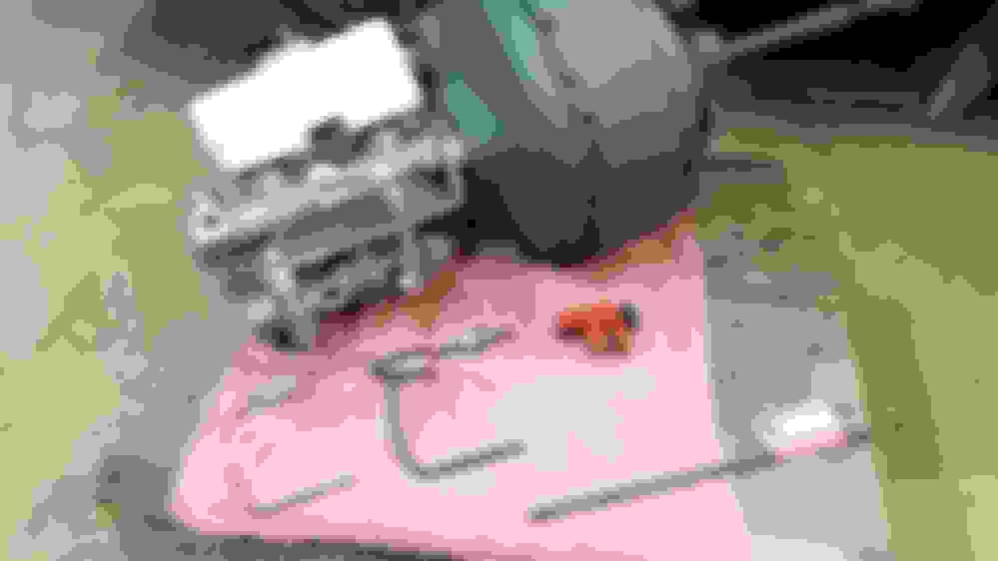
Before I milled the angled bracket though, I went ahead and fabricated the first two (out of the five total) brake lines that would have to be made to plumb the system out.
Making sure the tube fittings and that this line would line up with the ports, before putting the gravel guard and the loose SAE inverted flare nut fitting back on and then double flare this end of the tube --the fitting on this line (that will go into the forward most port of the MC --goes to the rear brakes) is an ISO M12 x 1.0 metric bubble flare fitting. I bubble flared that end of the 3/16" tubing for this. The other end of the same 3/16" tubing has an SAE 45� 3/8"-24 inverted flare fitting on it. I double flared the lower end of this tube for the 3/8"-24 fitting to go into the brake valve port.
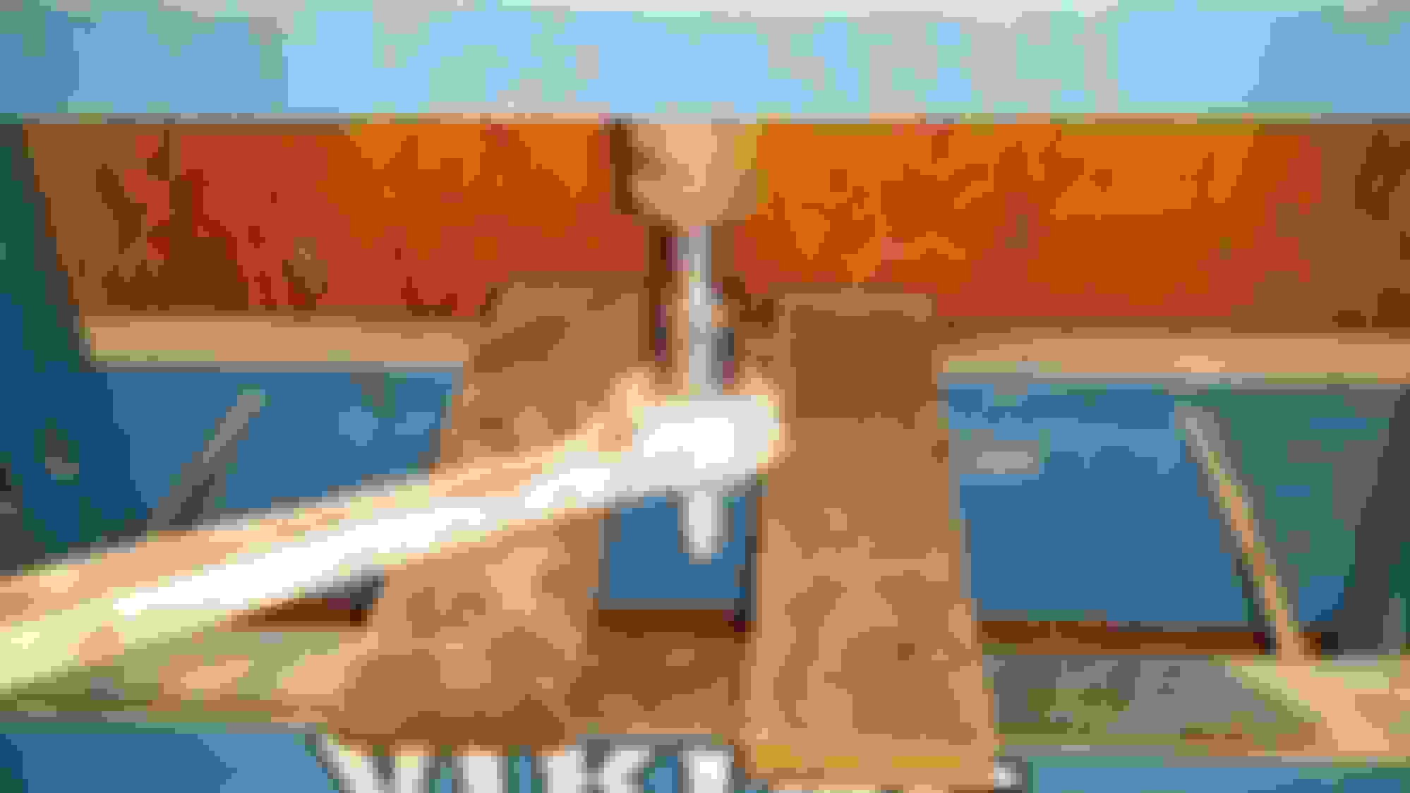
This is my Mastercool hydraulic line flaring tool I used to make all the metric and SAE flares in these lines with. I bought it in 2009 and hardly ever touch my old Gould-Imperial manual SAE 45� flaring bar anymore. I've had my old G-I manual flaring bar/yoke since 1984.
During the disc brake conversion on this '72 F100, I had made a somewhat similar angle bracket (to the one on the brake valve mounting bracket), to mount to the top of the steering gear box, to support the long lengths of the three brake lines coming downward from the brake valve.
I screwed a 3/8"-16 coupling nut onto one of the existing studs sticking up off the steering gear box and bolted the angle bracket to the upper end of the coupling nut.
Here, I was trying to figure out how I was going to make this work and what would need to be done to secure the lines to the support bracket --makes things more difficult when the lines hadn't actually even been run at this particular phase of the conversion.
I slotted this bracket (similar to what I had done on the angled piece that's on the brake valve bracket) and, I secured the two lines in the front with rubber insulated stainless steel Adel clamps wrapped around each of those lines.
At the left rear of the bracket, I attached another 3/8"-16 coupling nut to reach out and catch the line going out to the left front wheel. I made a small 1/8" thick aluminum tab to bolt to the coupling nut at one end and attach the Adel clamp to the other end of the tab.
After I ran these three brake lines, this is how they were secured.
 09-28-2016, 11:10 PM


 This image has been resized. Click this bar to view the full image. The original image is sized 1999x1124.
 This image has been resized. Click this bar to view the full image. The original image is sized 1999x1124.