If you've installed a dorman choke tube replacement.... Pls stand up
#1
 08-31-2016, 12:08 PM

Join Date: Aug 2016
Posts: 504
Likes: 0
Received 0 Likes
on
0 Posts
If you've installed a dorman choke tube replacement.... Pls stand up
Ok. So I'm gonna fix the carb today. Got my mind set on it... Yea. Bought the dorman 55111 as many suggested and am looking to put it on. I'm having issues figuring out how the simple contraption works as I'm assuming I need a way to flange the tubing or else the compression fitting at the carb won't work obviously. Yes?

Here's the kit. How does the shield connect to the tubing? Then the tubing to the carb? I see both a silver and gold tubing connection and a flared coneshaped thing and also the little ball. Any help. I could use it.

Also after taking a haaaard look I found this.... Is this the factory hole?

Ps. I can't believe there's not 1 YouTube video or walk through on this kit...
#2
08-31-2016, 12:23 PM

Ok, I'd stand up, but you won't see me from there. LOL!
It's been 25 yrs or so?
Anyway, if you remove the rubber plug from the carb I think you will see it does take a nut/ferrel to attach the tubing. Try threading the nut on? Should fit. Slip nut/ferrel on tubing and slip it in and tighten. Should hold it.
I don't really know what all the other hub-bub parts are about, but I just clamped the housing around my header tube(I had headers on my '70 F100 back then) and then hooked the tube to the carb and stuck it into the small hole in the housing. Done.
Found this picture online:
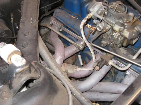
Not same motor(looks like 6 banger in Falcon or Mustang), but shows how it all goes together.
It's been 25 yrs or so?
Anyway, if you remove the rubber plug from the carb I think you will see it does take a nut/ferrel to attach the tubing. Try threading the nut on? Should fit. Slip nut/ferrel on tubing and slip it in and tighten. Should hold it.
I don't really know what all the other hub-bub parts are about, but I just clamped the housing around my header tube(I had headers on my '70 F100 back then) and then hooked the tube to the carb and stuck it into the small hole in the housing. Done.
Found this picture online:
Not same motor(looks like 6 banger in Falcon or Mustang), but shows how it all goes together.
#3
08-31-2016, 01:09 PM
Join Date: Aug 2016
Posts: 504
Likes: 0
Received 0 Likes
on
0 Posts
#4
08-31-2016, 01:29 PM
Hotshot
Ok. So I'm gonna fix the carb today. Got my mind set on it... Yea. Bought the dorman 55111 as many suggested and am looking to put it on. I'm having issues figuring out how the simple contraption works as I'm assuming I need a way to flange the tubing or else the compression fitting at the carb won't work obviously. Yes?
Here's the kit. How does the shield connect to the tubing? Then the tubing to the carb? I see both a silver and gold tubing connection and a flared coneshaped thing and also the little ball. Any help. I could use it.
Also after taking a haaaard look I found this.... Is this the factory hole?
Ps. I can't believe there's not 1 YouTube video or walk through on this kit...
#5
08-31-2016, 01:29 PM
Hotshot
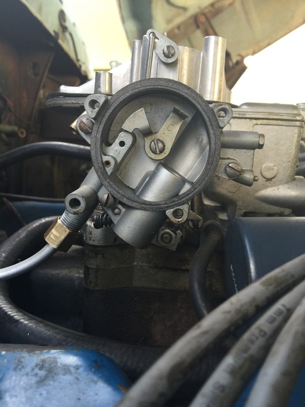
Found this on another site.
Here is the manifold end of the old tube, rusted off.
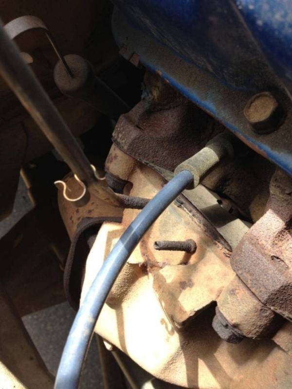
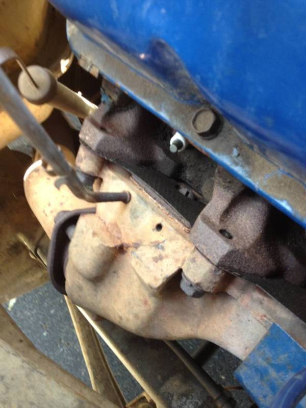
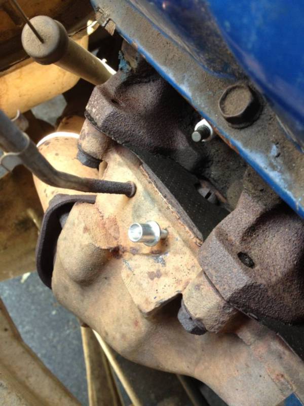
Because there was about a 1" stub, I was able to place some wood against the heads and pull it out with vice grips. However, in most cases it needs to be drilled out. The hole is supposed to be 3/16". If you need to drill it out, be sure to center the drill so it only drills the pipe stub, not the manifold. Because the old one is press fit in there, there will be a point where the part of the stub remaining in the manifold just spins out with the drill. Try and avoid getting metal shavings in the hole if you can. You don't want those being sucked into the choke. This is what it will look like. Note that in this shot you can clearly see the large screw (under the spark plug) that holds the plate on top of the void.
Take a LOT of care to blow out the void by pulling the tube off at the carb air horn and blow compressed air down it. Air and shavings should come out your newly drilled out hole. Do it 10 times. Do it 14 times actually. Now, get the universal choke kit from NAPA, pictured below.
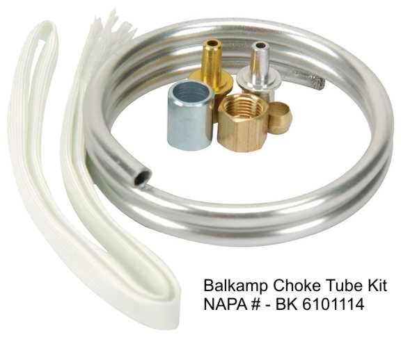
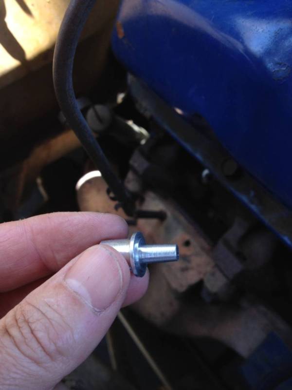
The silver tip is the one that you want to use in the 3/16" hole. You are going to tap it into the hole. If, like mine, your hole in the manifold is a little rusted, rather than drill it out more, I chose to slim the tip down a little. I did this by putting the tip in the chuck of my drill and spinning it in the drill while holding a piece of 80 grit sandpaper on the side. This shaved just a touch off it, making the whole tip a little narrower, but still tapered. Here it is slightly shaved down.
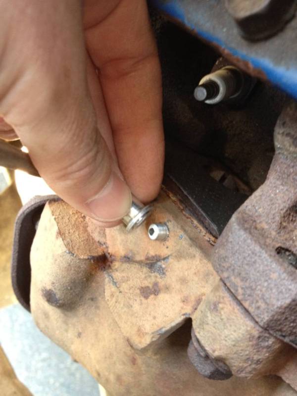
Next, you tap the tip into the hole by putting the larger round silver tube (from the kit) over it and hitting it with a hammer.
Take a lot of care doing this. It's a little tight in there. If you hit it hard off center, you"ll break it and you'll have to go to NAPA and lay out another $9.99. Don't ask me how I know this!
So to do it right, tap it in as straight as you can. I used a short length of rebar so I could get the hammer a little higher in the engine bay to tap it in. Once it's nice and snug, it's all good.
Now - the fun part. CAREFULLY unroll the aluminum tubing, stretching and pulling and straightening it out. I did this by kind of warming and rubbing it by using my two thumbs pointing upward and slooowwwwly straightening it out. Maybe sit in front of some NASCAR or a bizarre english detective series for a while to keep this a slow process. Once it's straight, I carefully put some smooth bends in it to match the one that was just hanging there. If you don't have one there you'll have to make it up or copy these pictures. I made it so it runs mostly parallel to the other tube, since they are clipped together just above the manifold. At the carb end, put the threaded fitting on the pipe, then the small pressure fitting collar and screw it onto the threaded female fitting on the choke. Sorry, didn't take pictures of that. This is the harder end to do because it's under the carb, so do this first and leave it just finger tight so you can take it off again. DON'T put the white woven cover on yet.
Now, make sure your bends all fit nicely from top to bottom. The pipe at the bottom will be too long (at least on my model). Try to match up with the tip that you've lightly hammered into the manifold and allow a little more length. Always easier to cut more off than add more on! Make a mark with a sharpie / marker. Unscrew it off the carb and take it somewhere like a bench to cut the end off at your mark. The tube crushes easily so use a saw or cutoff wheel, not clippers, which will crush the tube.
Clean up the end and dust off any filings. Dry fit it at the carb again finger tight. Now drop the newly cut end into the cup that's part of the tip. If you've left it a little long it will kind of "spring" into place with a bit of tension. If not, overbend it a lttle so it is held in place by tension. Here is what it should look like now.
If everything fits nicely, remove the bottom joint again and slide the white heat wrap onto it. This takes a little time, so you may feel like removing the whole thing from the carb end as well. Up to you! The ends of the wrap are frayed and there is no elegant way to make them un-frayed, even it you try manscaping it a bit. I even figured burning the ends might work but turns out the heat resistant wrap is heat resistant so it won't melt. Duh. So leave it, which is what I did. At the lower end I did clip the frayed part into the clip that joins the two tubes together. This is what the finished product should look like now.
And that's it! Good luck.
Because there was about a 1" stub, I was able to place some wood against the heads and pull it out with vice grips. However, in most cases it needs to be drilled out. The hole is supposed to be 3/16". If you need to drill it out, be sure to center the drill so it only drills the pipe stub, not the manifold. Because the old one is press fit in there, there will be a point where the part of the stub remaining in the manifold just spins out with the drill. Try and avoid getting metal shavings in the hole if you can. You don't want those being sucked into the choke. This is what it will look like. Note that in this shot you can clearly see the large screw (under the spark plug) that holds the plate on top of the void.
Take a LOT of care to blow out the void by pulling the tube off at the carb air horn and blow compressed air down it. Air and shavings should come out your newly drilled out hole. Do it 10 times. Do it 14 times actually. Now, get the universal choke kit from NAPA, pictured below.
The silver tip is the one that you want to use in the 3/16" hole. You are going to tap it into the hole. If, like mine, your hole in the manifold is a little rusted, rather than drill it out more, I chose to slim the tip down a little. I did this by putting the tip in the chuck of my drill and spinning it in the drill while holding a piece of 80 grit sandpaper on the side. This shaved just a touch off it, making the whole tip a little narrower, but still tapered. Here it is slightly shaved down.
Next, you tap the tip into the hole by putting the larger round silver tube (from the kit) over it and hitting it with a hammer.
Take a lot of care doing this. It's a little tight in there. If you hit it hard off center, you"ll break it and you'll have to go to NAPA and lay out another $9.99. Don't ask me how I know this!
So to do it right, tap it in as straight as you can. I used a short length of rebar so I could get the hammer a little higher in the engine bay to tap it in. Once it's nice and snug, it's all good.
Now - the fun part. CAREFULLY unroll the aluminum tubing, stretching and pulling and straightening it out. I did this by kind of warming and rubbing it by using my two thumbs pointing upward and slooowwwwly straightening it out. Maybe sit in front of some NASCAR or a bizarre english detective series for a while to keep this a slow process. Once it's straight, I carefully put some smooth bends in it to match the one that was just hanging there. If you don't have one there you'll have to make it up or copy these pictures. I made it so it runs mostly parallel to the other tube, since they are clipped together just above the manifold. At the carb end, put the threaded fitting on the pipe, then the small pressure fitting collar and screw it onto the threaded female fitting on the choke. Sorry, didn't take pictures of that. This is the harder end to do because it's under the carb, so do this first and leave it just finger tight so you can take it off again. DON'T put the white woven cover on yet.
Now, make sure your bends all fit nicely from top to bottom. The pipe at the bottom will be too long (at least on my model). Try to match up with the tip that you've lightly hammered into the manifold and allow a little more length. Always easier to cut more off than add more on! Make a mark with a sharpie / marker. Unscrew it off the carb and take it somewhere like a bench to cut the end off at your mark. The tube crushes easily so use a saw or cutoff wheel, not clippers, which will crush the tube.
Clean up the end and dust off any filings. Dry fit it at the carb again finger tight. Now drop the newly cut end into the cup that's part of the tip. If you've left it a little long it will kind of "spring" into place with a bit of tension. If not, overbend it a lttle so it is held in place by tension. Here is what it should look like now.
If everything fits nicely, remove the bottom joint again and slide the white heat wrap onto it. This takes a little time, so you may feel like removing the whole thing from the carb end as well. Up to you! The ends of the wrap are frayed and there is no elegant way to make them un-frayed, even it you try manscaping it a bit. I even figured burning the ends might work but turns out the heat resistant wrap is heat resistant so it won't melt. Duh. So leave it, which is what I did. At the lower end I did clip the frayed part into the clip that joins the two tubes together. This is what the finished product should look like now.
And that's it! Good luck.
#6
08-31-2016, 01:35 PM
Wow Jeff, great work.
My thought is if you don't want to go through all that, you could just clamp the little housing to the Y pipe just behind the manifold clamp. If the tube is long enough?
The alum tubing just sticks into the hole on the end of the housing you clamp to the pipe. Nothing else to it.
On the stock set up, it draws air in from under the air cleaner, down to the manifold, then up to the choke(thus the two lines shown in Jeffs pictures). The air then enters the engine. Thus is why it gets it from inside the air cleaner, so it is clean. This new set up you have won't have "clean" air. Not that I'd worry that much about it.
#7
08-31-2016, 01:39 PM
Hotshot

Trending Topics
#8
08-31-2016, 01:41 PM
#9
08-31-2016, 03:39 PM
Hotshot

#10
08-31-2016, 04:33 PM
Join Date: Aug 2016
Posts: 504
Likes: 0
Received 0 Likes
on
0 Posts
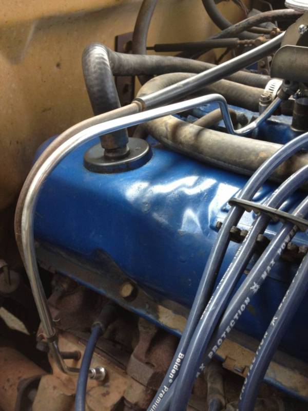
And the finished product
Ok everyone I think we are on to something. Thanks to freight and Jeff for the pointers.
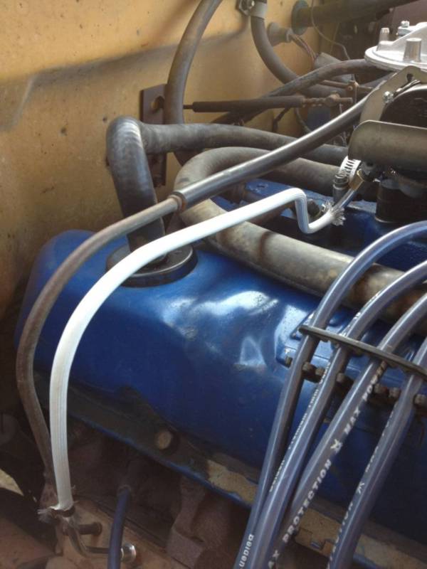
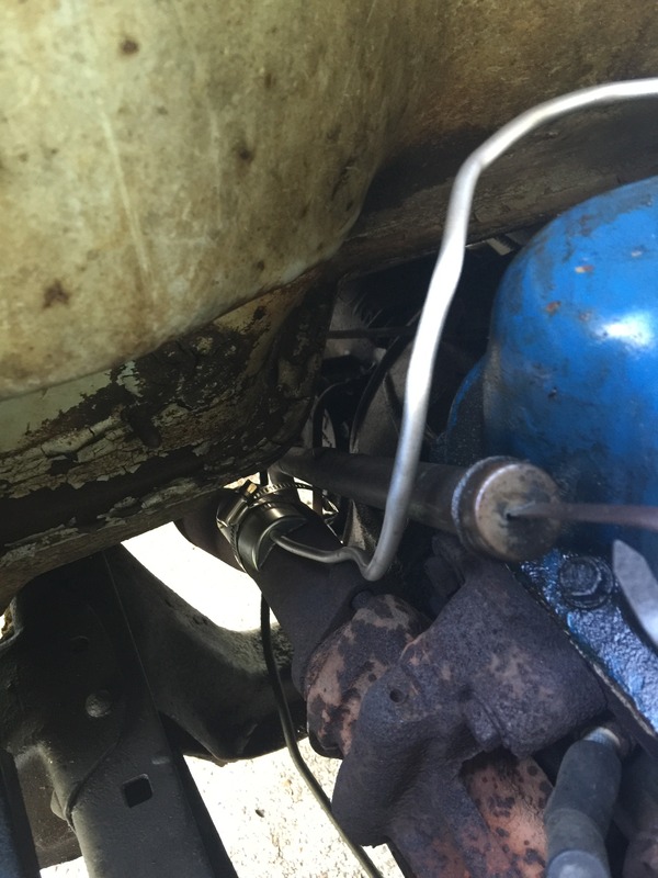
I decided not to go with the internal mount, primarily because I'm not gonna waste the time when these headers are going to be leaving at some point. So I strapped it to the side of the right contortion section of the header pipe.
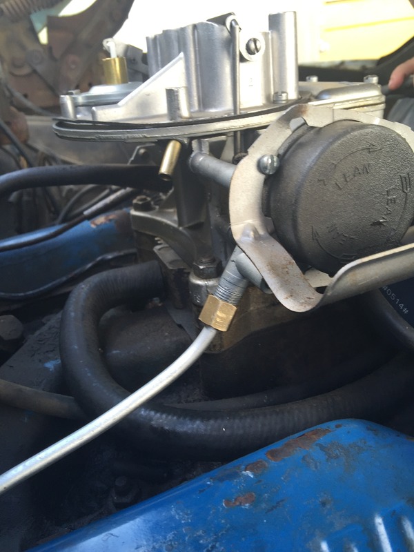
First off cause I know some other newb will need to know. Google ferrule and compression fitting. That will help. Anyway. Here's is the tubing snugged down while I was working with it.
Side note: don't bend it too dramatically in the wrong direction. It won't go back so well to its previous shape. Small tedious moves are the key.
Next I pulled the choke cap off, grungy but still tight.
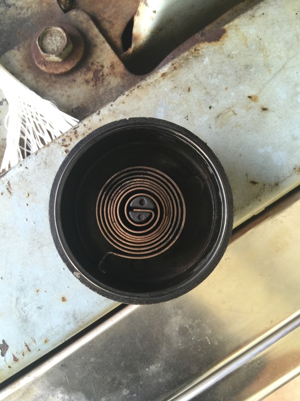
Here's the inside of the choke housing
And here's where I mounted the shield with the other end of the tube. Were I going to leave this for years I would have been more careful with my bends. I know we've got some very particular guys here, trust me I know they are sloppy. My focus was keeping it as close to the heat source as possible.
And for good measure I took a video showing operation of t an showed the adjustment of where I set the choke. What do you guys think as far as spacing. Pretty close to 3/32.

I decided not to go with the internal mount, primarily because I'm not gonna waste the time when these headers are going to be leaving at some point. So I strapped it to the side of the right contortion section of the header pipe.
First off cause I know some other newb will need to know. Google ferrule and compression fitting. That will help. Anyway. Here's is the tubing snugged down while I was working with it.
Side note: don't bend it too dramatically in the wrong direction. It won't go back so well to its previous shape. Small tedious moves are the key.

Next I pulled the choke cap off, grungy but still tight.

Here's the inside of the choke housing

And here's where I mounted the shield with the other end of the tube. Were I going to leave this for years I would have been more careful with my bends. I know we've got some very particular guys here, trust me I know they are sloppy. My focus was keeping it as close to the heat source as possible.

And for good measure I took a video showing operation of t an showed the adjustment of where I set the choke. What do you guys think as far as spacing. Pretty close to 3/32.
#11
08-31-2016, 04:45 PM
Hotshot
What is 3/32"?
If you can still sneak that choke tube sock over it from the bottom up you should. It should have come in the kit. It helps hold the tube's heat in it. Since you're not going to replace the filtered supply air tube, don't forget to put the rubber cap back on the carb air horn nipple.
If you can still sneak that choke tube sock over it from the bottom up you should. It should have come in the kit. It helps hold the tube's heat in it. Since you're not going to replace the filtered supply air tube, don't forget to put the rubber cap back on the carb air horn nipple.
#12
08-31-2016, 05:32 PM
Join Date: Aug 2016
Posts: 504
Likes: 0
Received 0 Likes
on
0 Posts
What is 3/32"?
If you can still sneak that choke tube sock over it from the bottom up you should. It should have come in the kit. It helps hold the tube's heat in it. Since you're not going to replace the filtered supply air tube, don't forget to put the rubber cap back on the carb air horn nipple.
If you can still sneak that choke tube sock over it from the bottom up you should. It should have come in the kit. It helps hold the tube's heat in it. Since you're not going to replace the filtered supply air tube, don't forget to put the rubber cap back on the carb air horn nipple.
#13
08-31-2016, 05:43 PM
Hotshot

#14
08-31-2016, 07:05 PM
#15
08-31-2016, 07:46 PM
Join Date: Aug 2016
Posts: 504
Likes: 0
Received 0 Likes
on
0 Posts
I still need to re cap that top brass inlet. From what everyone said that's a fresh air inlet.... Guess it's not needed and can be capped without issues?!?
As far as adjusting the idle, I never heard it kickdown or slow as the butterfly was opening. Makes me wonder if the high idle isn't set high enough and so when the motor warms up its not changing rpm and the regular idle isn't having to "change" down to the warm idle. What do y'all think. Without a tach it's hard to tell what the high idle on cold should be? Any suggestions?