When you click on links to various merchants on this site and make a purchase, this can result in this site earning a commission. Affiliate programs and affiliations include, but are not limited to, the eBay Partner Network.
1950 F3 12 volt conversion with pictures and parts
There have been many threads on this subject to convert a Flathead 6 volt system but I thought I would pull together all I learned from this forum and go into detail with pictures and parts I found to convert the wiring.
I AM NOT AN ELECTRICAL ENGINEER AND CANNOT SAY WHAT I HAVE DONE MEETS THEIR REQUIREMENTS OR RECOMMENDATIONS. IF YOU USE ANY PART OF WHAT I DID, PLEASE PROCEED WITH YOUR OWN CAUTION. MINE WORKS AND I AM HAPPY WITH WHAT I HAVE DONE.
First I made up a list of my requirements:
1. I would use a one wire alternator.
2. I would use the MSD Ready to Run distributor with MSD ignition wires and coil.
3. I would use a 12 volt starter relay.
4. I would convert my starter to 12 volts.
5. I would run my own wiring and not use a pre-made wiring harness.
6. I would crimp, solder and heat shrink each connector.
7. I would use 2 fuse blocks. One that was "hot' all the time from the battery. The other would run off a 30 amp relay controlled by the ACC position of the ignition switch.
8. I would use relays to run the high and low beam positions of head lights.
9. I would grounds to each circuit not counting on frame, can or engine grounds. The only exceptions to this would be the alternator would use the engine block for ground. The horn switch would use a ground through the cab/frame.
10. I would use a WPM to control the fan speed of the 12 volt heater motor.
11. I would use the original gauges with two temperature gauges and no amp meter. I would install a voltage meter in a cigarette lighter. The gauges would use 12 to 6 volt converts with the bulbs being 12 volt.
12. I would use LED taillights.
13. I would use a STAT 900 turn signal switch.
My vendors while not the cheapest had great quality:
1. I use M.A.D. Enterprises in Springfield, CA to get wiring and relays. They also provided valuable information on tools and "how to's".
2. I used Racres INC in Couer D' Alene, ID for all my wiring other than the man positive and grounding wires. I went with all black. Below is an example of the wires I got to use for my gauges.
3. The next vendor I used was MSD for the distributor, coil and spark plug wires.
4. All my battery cables I got from NAPA. Any auto parts store would do but I like the staff at my NAPA store. The positive cable is a red gauge 1 cable 12 inches long. The negative cable is 35" 1 gauge long black cable. There is a 2 gauge red cable running from the starter relay to the starter. There is a black 2 gauge cable running from the starter body to the bolt holding the starter relay on the cab.
5. I used Blue Sea Systems for my two fuse blocks and various grounding blocks. They basically make wiring for boats so they are big into grounds. Their 12 circuit fuse block has a grounding set of terminals I used. I also bought grounding blocks to use in the wiring. I purchased them through Amazon.
6. I used Dennis Carpenter for light switches, etc.
7. I use Classic Haulers for starter relays, parking lights etc. I think there are many other great truck vendors that can supply these items, so use the ones that are yout favorites.
Wiring - Lets start at the battery.
As I mentioned in my goals I want all grounds to go directly to the negative side of the battery. So I ran a 1 gauge wire from the battery to the bolt holding the starter to the engine. That same bolt has a grounding strap going to the frame. The bolt also has a 2 gauge wire connecting to the back of the mounting bracket on the starter relay. There is a cut off switch on the negative battery cable.
Next the positive side of the battery goes to the other side of the starter relay. Connected to that same side is the red cable from the 1 wire alternator. The finally wire is a red wire that runs to a positive distribution block next to the firewall hole. That wire has a fuse-able link from M.A.D. to protect that circuit.
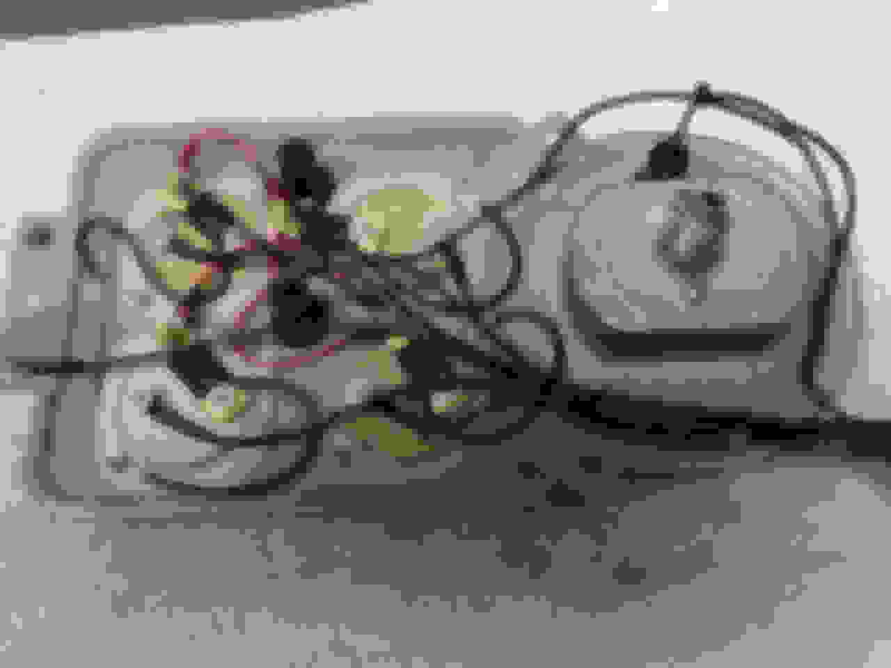
Finally the right side of the starter relay mounting bolt has a grounding wire that is running to a 4 wire Blue Sea System grounding strip located on the left inner fender panel. See the picture below.
Now it is time to go inside the cab and wire the fuse blocks. I ran two main wires into the cab. One is a red wire from the positive distribution block I got from M.A.D to the 12 circuit "hot' Blue Sea System fuse block. I ran a black ground wire from the 4 lug Blue Sea system terminal strip into the top of the 12 circuit Blue Sea system negative ground. The other wires entering the cab at this time are the two temp sending wires, the coil wire, the starter wire, and the oil sending unit. They will be connected later. See the wiring picture of the left inner fender to see the 4 lug Blue Sea System terminal strip and the wire runniong into the cab.
Wiring showing 4 lug terminal strip and ground wire running into cab
The next picture show s the two Blue Sea system fuse blocks. The fuse block on the right has a black ground wire going to the top with the red positive wire on the bottom from the positive distribution block on the fire wall.
The 12 circuit fuse block on the right has a red positive cable at the bottom and a black ground cable at the top.
Now that I had power and ground into the cab I proceed to wire the interior.
The first thing I wanted to wire was the other Blue Sea System fuse block. I took a wire from the 12 circuit fuse block and ran it to the ignition switch. I then took a wire from the ACC position on the ignition switch and ran it into a 30 amp relay. The other side of the ignition switch was wired using the coil wire I had run into the cab previously. That ACC relay was grounded to the grounding terminals at the top of the 12 circuit fuse block. The is a 30 amp circuit in the right fuse block that goes through the ACC relay to power the top 4 circuits of the right fuse block. In this way when the ignition or ACC is on, the top 4 circuits get power. The 4 ACC circuits will be the Heater, Radio, Cigarette lighter and Gauges.
Next I started with the heater which is the left most device in the front of the cab. I wanted to have 4 items control my heater. Two were going to be mechanical cables to control diverting heat from the heater to the defrost and a cable to let water into the heater. I got a heater control valve from Classic Haulers to use with the HEAT control cable. These would become the two right most positions of the heater control panel.
The other two positions of the heater control panel would contain the **** that controls the speed at which the motor turns. Since I was going to use a WPM, I had heard that it leaks current and is never truly off. So I purchased a 15 amp 0n/0ff switch on Amazon to control power to the WPM. I also purchased the WPM from Amazon.
The 4 hole heater control panel came from Dennis Carpenter. I went to a local graphics company to have the labels made. I had them done in red letters with a black background to match the 1950 **** colors. Since the heater control fitted so close the bottom of the dash, I took a 1/4" piece of aluminum bar stock and lowered the heater control so it could be easily seen. I ran a ground to the WPM circuit to complete the circuit. The WPM is mounted to the dash using two pieces of aluminum stock and the mounting bolts that hold the heater control panel to the dash. (Note, I needed new handles for my heater doors and found that Dennis Carpenter has a 1941-48 set that fit perfectly.)
The Radio was the next thing to be installed. In a previous post I showed how I made the Retrosound radio fit into the dash. I had also purchased the Retrosound speaker system that allows you to get a stereo like sound though one speaker. The radio needs three connections. One is a constant 12 +v to retain the memory of the buttons for each station. The next is a 12 v power when the radio is on, The final is a ground. So I ran a 12 V+ from the left fuse block for constant power. The radio on/off power comes from the right fuse block. The ground comes from the ground block of the left fuse block. See the fuse blocks in a previous pictures for the connections.
Now that the radio was installed I needed to install the cigarette lighter. The original had it installed hanging from below the dash. I wanted a cleaner look and found that the hole in the column drop used for the three on the tree shifter held a cigarette lighter perfectly. So I purchased one from my local auto parts house (I do not remember where I got it.)
The only problem in placing the cigarette lighter there is that the bolt that holds to column drop together is in the way. There are two ways to solve this. One is to bend to bolt so it will fit. The second is to remove the bolt after ensuring the column drop was SECURELY attached to the dash. The lighter socket was installed and wired. Again it takes two wires - a ground and 12 volt positive. The ground comes from the grounding block of the right fuse block. The power comes from the ACC part of the left fuse block. The volt meter was purchased from Amazon.
The volt meter installed in a cigarette lighter socket in the hole used in the column drop for the three on tree shifter.
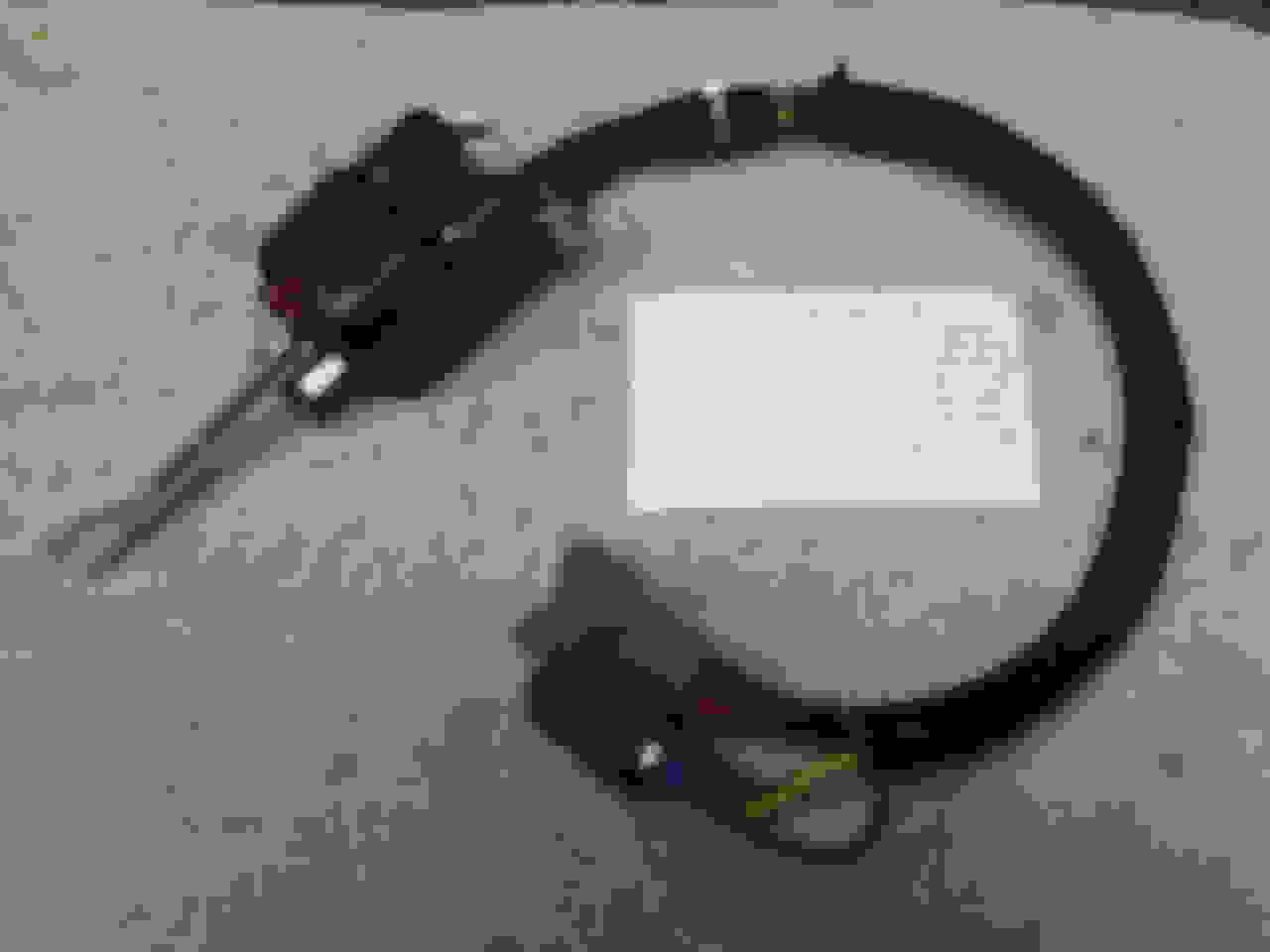
Now I was ready to install the Truck-Lite Series 900 turn signal purchased on Amazon. It requires multiple connections. I decided to use a 8 pole connector so the switch would not be hard wired into the truck. I used 7 of the 8 positions in the connector. Again I ran a ground wire into the connector as one of the connections. The wiring is fairly straight forward. I used one of the right circuits off the "hot" circuit fuse block to power the switch. The only problem I had was with the turn signal relay. Since I wanted to use the LED rear lights I had purchased through Classic Haulers, the standard relay did not work. I had to go to O'Reillys to get a relay that ran both LED lights and convention and bulbs. The connector I got through O'Reillys auto parts but cannot remember the brand.
Turn signal wiring showing how each position in the connector is used.
With the turn signal wired it was time to hook up the horn. Classic Haulers has a kit that allows you to use the original horn switch if you have done a Tacoma Power Steering conversion. It is expensive but it works. If you keep the original steering box, you have no worries. I ran a relay from the right side "hot" fuse block for the switch. The horn uses a ground through the horn button so the relay's ground side line was run to the horn contact in the steering column. I then ran the power side of the horn relay to the front of the truck to attach to the horn. See previous picture of fuse blocks.
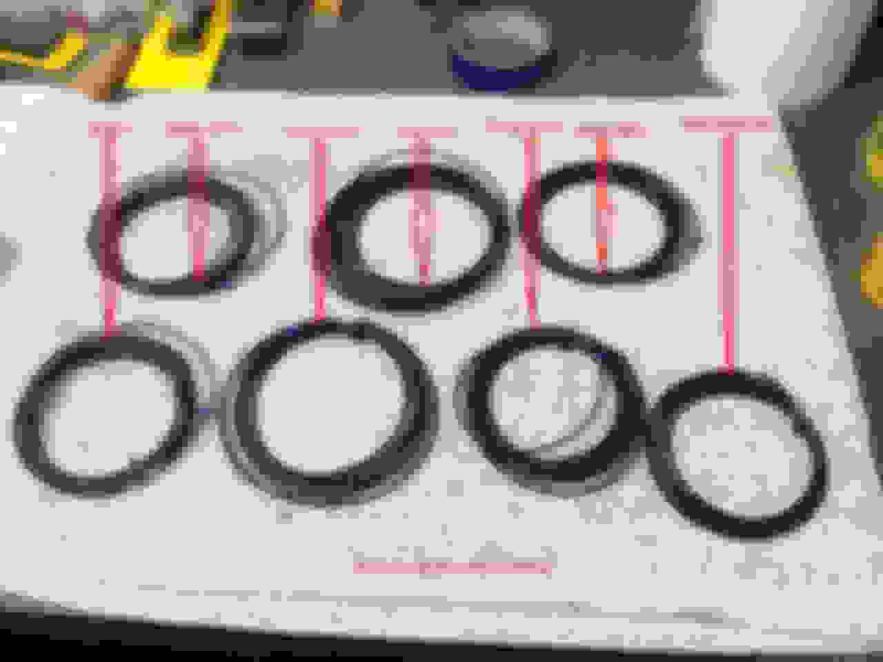
The next thing to wire was the gauges. I ran a 12 volt to 6 volt adapter for each gauge. I replaced each bulb with a 12 volt light bulb. This included the 2 lights for the gauges when the parking lights are on and the hi/low beam indicator. I also ran a hard ground from the gauge case. All of this went trough an 8 pin connector also purchased from O'Reillys.
Gauges showing the 4 - 12 to 6 volt converters. The ground wire is also shown connected to the left side of the gauge housing.
With the gauges wired I then wired the light switch. I was going to run Halogen headlights so I wanted to use relays to power them.
There are two hot feeds into the switch. I allocated two of the "hot" fuse block fuses to this. The only thing I did special was run the lead from the switch when the rear parking lights are on into a fuse on the left 6 circuit breaker box to protect the two bulbs in the gauges when that circuit has power. I also ran the high beam circuit wire that feeds the hi bean indicator through another one of the fuses on the 6 circuit fuse box to protect that circuit. See the fuse block diagrams for those two circuits. I will discuss later how I wired the front end.
Next was the wiring of the starter button. Most people require the ignition to be on to run the starter. I decided to wire mine so that I could press the starter with the ignition off and the engine would not start. In this way I could turn the engine over and check for water, gas, and oil leaks with out the engine running. I probably over thought that and would now run the starter through the ACC fuse block.
The last circuit was the dome and fuel sending unit. I ran the dome light off the "hot" fuse block so the light could be turned on with the ignition/ACC off. I also decided not to install a set of door switches to activate the dome light. You must turn it on with the on/off switch if you want light. In this way when you are at the drive in you can open the door and not flood your neighboring cars with light.
The gas sending unit is wired into the gauges. Both the gas gauge and the dome light have a hard wire to the grounding block of the 12 circuit "hot" fuse block.
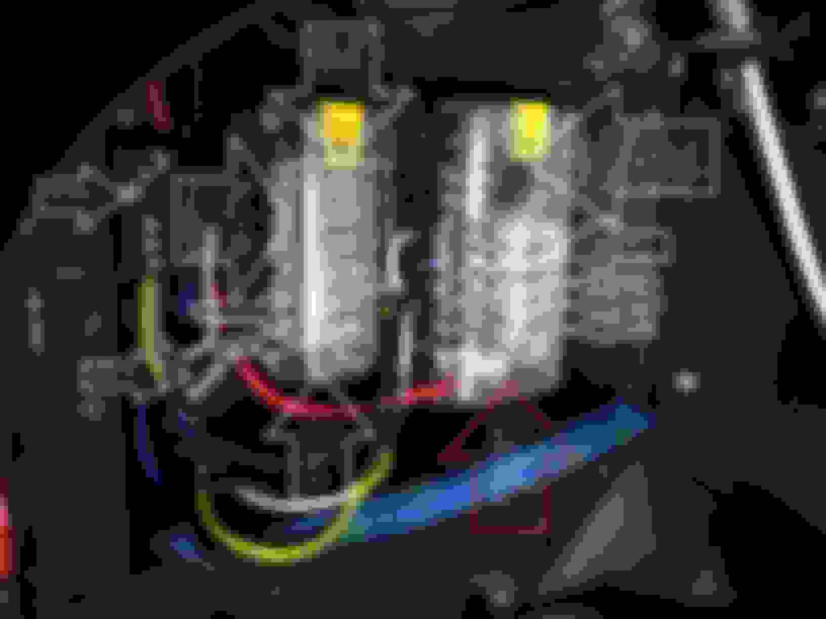
For the headlights there are two relays: one for the high beam and one for the low beam. These receive 12 volts through a 30 amp circuit breaker feeding directly from the battery/alternator. The relay are BOSCH relays purchased off Amazon. The good thing about these relays is that once they are triggered by the dimmer switch they have two outputs. In this way each relay can have a left and right circuit run off them to each of the headlights.
So let's look at the wiring for the headlights. There is a high and low relay. Each relay powers either two headlights with two wires running from each relay to each light. There is also a ground running from the grounding strip to each light.
The parking lights had the following problems to overcome. The standard parking light housing has a 6 volt single element bulb. I needed a two element bulb so I could have both a turn signal and a parking light. Classic Haulers sells the parts to convert the housing from 6 to 12 volts plus 2 element lights. You must replace the bulb housing with the two prong housing provided by Classic Haulers. I had to take the parking light housings to my local body shop to have them press out the 6 volt housing and press in the 12 volt two prong housing. I was then good to go. Now each parking light has three wires coming from it. A parking light, the turn signal wire and a ground I hard wired to the housing. I wired these through a 3 wire water proof connector I got off Amazon so I could easily disconnect each of them. The parking light side of the wiring goes to the power strip on the left inner fender where it is broken into two outputs to feed each light. The turn signal part is run directly from the turn signal switch.
The horn is the only thing left to connect. I already had the horn wire running from the relay to the front of the truck. I purchased an universal single horn from O'Reillys since my truck only had a mounting bracket for one. It was straight forward to wire. Horn wire from relay and ground wire in my case going to the grounding strip on the inner fender.
Circuit breaker and headlight relays. The terminal strip in front of the relays terminate the grounds from the relays, headlights, parking lights and horn. It also allows the single parking light coming from the light switch to be split into two outputs - one for each parking light.
All that is left is the rear. I ran a ground wire all the way to the back terminating it in a terminal strip so the two rear lights plus license plate light could have a ground. The rear parking lights also terminate into a terminal strip so I can break out wires for each rear light and the license plate light. The rear turn signal/brake light wires run directly to their respective light. The LED rear lights were purchased from Classic Haulers. The terminal strip was a Blue Sea System item purchased from Amazon.
 04-17-2016, 07:19 PM