When you click on links to various merchants on this site and make a purchase, this can result in this site earning a commission. Affiliate programs and affiliations include, but are not limited to, the eBay Partner Network.
You had better lubricate that Ford VRV. I enlarged the photos and I can see the yellow dust from the wear! Wear on the corner edge of the cam ramp it looks like...
Fixnstuff, the shape of the post is rectangular/squarish, and the yellow rod is identical to the black rod in shape. If you look at the photos of the black one, the post is a square not quite as wide as the link rod. I suspect the material has changed to a slipperier plastic with the black, but that is purely a subjective feeling of texture.
I got another GM VRV of the older type, 14057219 from eBay, (without the wires), and it contains the same link rod in black plastic, so things are looking good for replacing everything except the cam on old Ford VRVs.
i'll take the Ford VRV back apart and take a picture straight down of the cam. It may take couple of days to get back to it, I'm moving so things are a bit chaotic....
Comparing the Ford and GM casings, they are indeed mirror images of each other. I'll get a picture of that as well.
Strategy for now, I'm going to have my mechanic swap out the Ford VRV with the later model I got on eBay, and keep you posted on the results. He has the tools and scanner to set the VRV properly.
I'll find out what he says the old VRV it isn't doing and then try a rebuild with the new link rod. Ideally, I would like to try the rebuilt one back in the engine, but I don't have the funds for that right now.
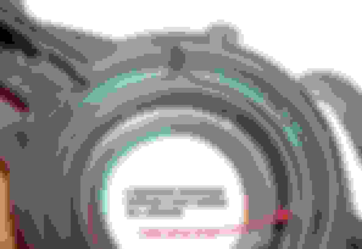
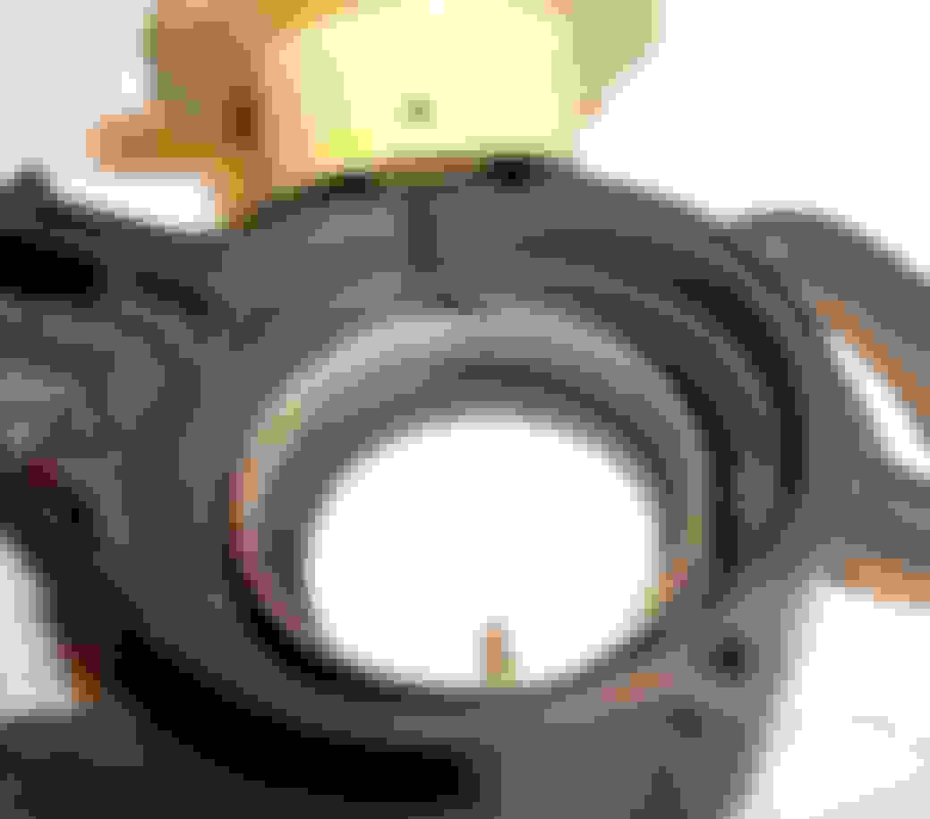
Fixnstuff, here are the pictures of the cam and one is from an angle shows the shape of the post on the rod. Also, I proper the two VRVs, Ford and GM, back to back showing the mirror imaged casing.
Back to Back VRVs from GM and Ford (to the right)
Angled, no flash
Flash lit, from top. I worked to get the best angle, light...
Thank you! I hope you haven't installed your replacement Ford VRV in your truck yet because it is NOT ready to install. I'll show you why, with an enhanced photo and what to do about it in my next post. That post will be followed by another very important post with images, related to using a GM VRV to repair a Ford VRV. The first post will be coming up shortly, followed by the second which will take a little bit longer so watch for both of them.
Sorry it took so long to get back- I won't bother to explain why but I did spend about 6 hrs last night figuring some things out and wrote about 7 pages of very detailed info., (felt like I was writing a textbook) but I'm just going to address what is important at this moment, in 3 posts.
FIRST:
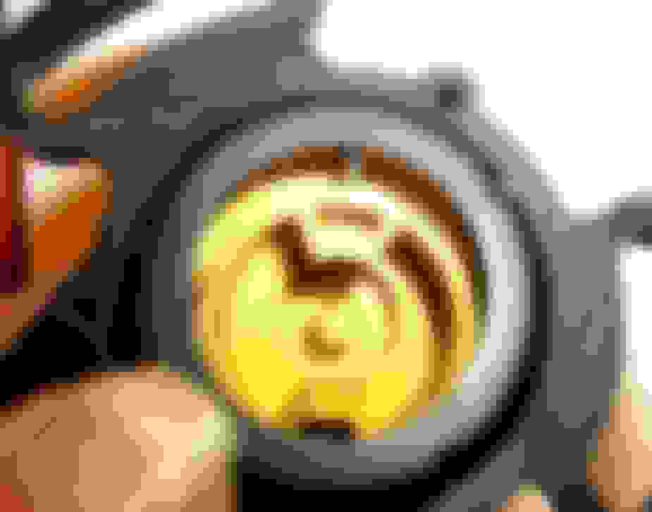
Here is a magnified (11x) and enhanced photo of the most important part of the CAM in your replacement Ford VRV:
CAM WEAR & DIRT
You can clearly see the wear on the cam ramp and particles of yellow plastic that came from the ramp and from wear of the post on the link rod, plus the DIRT. (It's called a 'ramp' because the curve that the cam link post slides against is like a ski ramp). Dirt is an enemy of those moving parts, even after lubrication.
Dirt gets inside through two small ventilation slots on the back side of the VRV (behind/under the cam). From the back side, the slots are located at 6 o'clock and 9 o'clock when the VRV is pointing straight up. The slots are for ventilation to remove moisture / condensation from inside the VRV which is very important to protect the metal parts of the valve assembly from corrosion, so those slots should not be sealed.
My personal recommendations:
The whole outside of your replacement VRV is filthy dirty (as you'll see in the post following this one) and both the inside and the outside of your VRV needs to be scrubbed clean before it can be properly lubricated and installed in the truck= everything visible and accessible except for around the valve housing under the dust cap.
You'll need to be careful not to get water inside of the top part (valve assembly) through the slots in the top where the metal tabs come through (which are under the dust cap which will be removed and cleaned). The GM VRV does not have a dust cap- those slots at the metal tabs are sealed). Water can get in from underneath the center of the castle nut, in the middle where the end of the spring through that attaches to the link rod. Just don't put the top part under water and you'll be fine. You can just wipe the part off with a damp rag (after dust cap is removed) but the rest of it is going to take some serious cleaning before it can be properly lubricated and ready to be installed. If you don't do this you'll be taking a big risk of wearing out a good VRV long before it's time.
That amount of dirt is not “normal” for a truck driven on paved roads. The VRV on my truck is the same vintage and is so clean it looks brand new in comparison to yours.
I presume that yours got that dirty from driving on very dusty gravel or dirt roads and/or off-road in dusty conditions. Typical of rural agricultural use, construction sites or off road recreation. Portions of such dust contains very fine silica (quartz) which is very hard, harder than steel and will scratch steel when pressure is applied as it moves against a steel part. Sometimes you can't see it without magnification- (see photos in the post following this one). Such dirt makes quick and easy work cutting into, scratching and wearing away plastic parts. I may have played a role in the wear you see in the photo. The objective here is to make your replacement Ford VRV last for a long time.
by the way, most of the wear is on the hump in the cam ramp. On the cam that I have here that hump is worn completely off. That whole curve regulates the tension on internal springs which control the position of the diaphragm inside, and thus the amount of vacuum in the line to the transmission. A worn cam and cam link will probably still work fairly well but will make the VRV much more difficult to adjust eg. to find the correct vacuum readings.
There is going to be some dirt behind (under) the cam because that's where it's coming from the two vent slots in the frame behind the cam. Therefore you'll need to remove the cam and the spring behind it that holds the cam in place and provides the spring tension to return it back to the low idle or 'off' position. Removing the cam and the link rod is by far the best way to clean and lubricate the VRV.
This is all EASY, IF you KNOW The trick to get the cam & spring out and properly re-installed back in the frame. Otherwise it could be frustrating trying to figure out how to get it out without bending the spring and to get it back in. I will show everyone how to do that with some close up photos (which I will take after the post that follows this one).
I scrubbed all of the parts in the bathroom sink (DRAIN CLOSED) with dish soap and a fingernail brush but this VRV was completely disassembled. I think I used some degreaser too. A toothbrush was helpful. Use any makeshift tool you can devise to get into the corners and small spaces. A screwdriver tip with a (wet/soapy) cotton cloth on the end was helpful to get into tight corners. You can clean it however you want and you'll see from photos I post later why removing the cam and cam link is by far the best way to clean it and lubricate it.
Now, on to the next posting.
Positioning the GM Valve Assembly on the Ford VRV Frame.
Here are two photos comparing the position of the castle nut that holds the valve assembly in it's correct positionfor each respective VRV. This 'correct position' is a very sensitive adjustment of spring tension on two different springs inside each of these valve assemblies which control the position of the diaphragm. The nut needs to be in it's correct position for the VRV to operate with it's factory set precision. (in a new VRV).
After it is set in correct position and installed on the vehicle, the adjustment procedure described in the Ford Shop Manuals can be carefully followed and be successful the first time. (if done properly). If this GM VRV Valve Assembly is not screwed down to the correct position on the Ford VRV threads then it will be more difficult to adjust and may not be adjustable at all with the shop procedure.
Notice that there is a very big difference in these respective positions between the two VRVs. SO, when you install the GM valve assembly onto the Ford VRV frame-threads. WHERE are you going to position the castle nut to obtain the correct internal spring tension?
Ford VRV - Threads Count:
Compared to:
GM VRV Threads Count:
As you can see, there is quite a difference. The GM valve assembly in the second photo showing less than a full thread exposed. This GM valve assembly will be screwed onto the threads of the Ford VRV in the first photo where the nut position is showing nearly 3 threads exposed. That is why I originally needed the dimensions between the bottom of the castle nut to the top edge of the cam slot or "ramp" for each VRV to determine exactly how far the GM valve needs to be screwed down onto the Ford Body.
HOWEVER, with these magnified and enhanced photos PLUS having a Ford VRV in parts here AND having a brand new GM VRV (same as yours - I received it 4 days ago) I WILL be able to calculate the exact position for the GM castle nut on the Ford VRV frame.
One factor I have to consider: The GM valve assembly is TALLER than the Ford valve assembly which means the internal parts are not the same. This might make it more difficult to calculate without taking the GM valve assembly apart, (which I am not going to do with this new one because the tab slots are sealed - but I will find a failed one or a cheap one from a wrecking yard to take apart later to see EXACTLY what the differences are). I expect the difference to be in flat spring that pushes up on the diaphragm or just the internal configuration. On the other hand this difference could make it all very simple to calculate. I'll know if it's going to be simple as soon as I start measuring, in which case I might be able to show the correct position tonight.
NOTICE THE DIRT on the Ford VRV under some magnification and enhancement. It certainly should be cleaned before it's properly lubricated and reinstalled on the truck. I'll show how to take it apart in the next post. (I have to take photos of the procedure first).
Finally, Trucknewowner, The following photo will show you how to remove the dust cap. You need to do this for 2 reasons. 1) Examine the prongs on the castle nut to confirm that they are still spot glued to the body of the valve assembly - which means that this is in fact the original factory setting and confirm that the glue joints have not been separated before and the castle nut turned. That's actually for my information so I will know that it is in fact the original factory position and I can proceed with other measurements here. I can duplicate that position exactly on the VRV that I have apart.
2) You will need to remove the dust cap to clean it up (inside & outside) and wipe off any dust or dirt on the valve housing).
Inside the gap you can see one of the prongs on the castle nut and how that lines up with a vertical fine line that crosses the threads. That is manufacturing mold mark where the molds were separated to eject the part. That is how I know exactly where the nut on your VRV is located and I don't need dimensions for that now.
At the bottom of the cap in that gap, pull the two corners of the cap to each side (making the gap wider at the bottom), then you can push it or pull it right off the top. The plastic is a bit stiff but springy. Some people just grab it, jiggle it around and pull it off, which is how I did it before. I showed you a close-up of how it is held on and a delicate way to take it off.
To put it back just put it over the top again, push down and it will snap right into place. This won't harm anything to remove it. It's just a dust cap Then you can wash it in soap and water and put it back on when you are ready.
Now I have to do the fun "Remove and Replace the Cam" pictures and instruction.
Sorry this is taking so long. I've put a lot of hours of work into the post that will be coming up, examining wear points under magnification, discovering new things that are otherwise not obvious, confirming details, taking, editing and enhancing lots of photos and more, all for a simple cam removal and reinstall instruction post but it has been worth it! What I've learned I will pass on to you.
Most of the work is done for the post about removing/reinstalling the cam. 8 close-up photos chosen that also show wear points that must be lubricated if you want a VRV to last longer. I would expect it to last at least 30-50% longer (conservative estimate) or more!... than it would without being cleaned and properly lubricated.
Since this working Ford VRV is so difficult to find and using the GM valve assembly and link rod to repair it does not renew the Ford cam and the frame (which gets significant wear), I think it's well worth the time and effort to protect these worn parts for as long as possible.
I'm approaching it like repairing a critical aerospace part in a clean room but why not? You, or someone else may have to use these same parts for a second rebuild so it makes good sense to take the care and do it the best way we can for a longer lasting VRV.
One correction from an earlier post: I warned about disconnecting the cam link from the spring and a risk of breaking the spring. That's not the case. The spring that broke was an old rusty spring on a completely different and unrelated assembly.
In this case: when disconnecting/reconnecting the plastic link from the spring in the VRV, there is no risk of breaking it but there could be a very slight risk of bending it. Being careful, that is unlikely to happen, it's spring steel.
The one I have hear did get stretched very badly to the point of being not usable or repairable. That is what I was thinking of at the time but that was not caused by removing the link. It was caused by mishandling. Someone tried to unscrew the top while the VRV was assembled and completely ruined that spring. (It was not me). All that I recalled at the time I warned about it in this thread was that the spring had been damaged beyond repair and that's why I urged so much caution about disconnecting it from the link. I later found the spring and remembered how it got damaged.
So, disconnecting and reconnecting the link, using needle nose pliers as Trucknewowner did is fine. It's not going to damage the spring unless you were to force it to the extent that it bends or stretches out of shape which is unlikely if you take average care in disconnecting and reconnecting it.
Trucknewowner, If you've already installed the replacement Ford VRV in your truck that's OK.
I don't mean to delay you by waiting for my work to get done.
... when you install the GM valve assembly onto the Ford VRV frame-threads, WHERE are you going to position the castle nut to obtain the correct internal spring tension?
I worked on this problem yesterday taking lots of measurements, etc. and had it figured out including how much adjustment it might need.
THEN, this morning I realized that all of this can be accomplished with ONE SIMPLE MEASUREMENT and the GM part can then be installed on the ford VRV threads and be in perfect adjustment.
The photos are easy to follow. Some of the instructions contain detailed observations for those who are interested, (mostly for the first photo) but don't let those observations distract you from the simplicity of this procedure as shown in the photos and in the basic instructions.
This is my first time using drawing tools in advanced graphics software so I'm in a learning curve but I had to get this finished and posted.
I've noticed that there is a lot of friction on several surfaces between the cam and the VRV frame as the cam turns. Due to cam-spring tension the pressure and friction on those surfaces is increased, eventually causing significant wear. I can see the abrasion under magnification and you'll see the result in some of these photos. This is the primary reason why the cam should be removed: to be properly cleaned and more importantly properly lubricated at those friction surfaces.
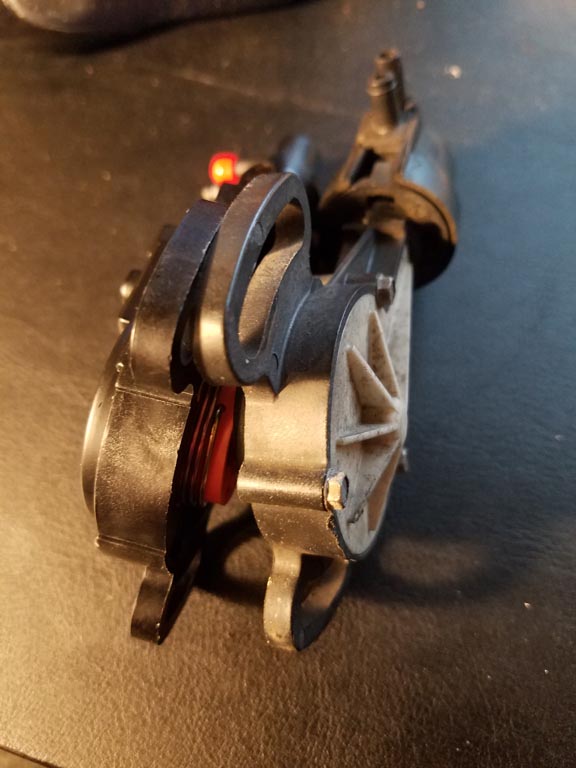
FIRST. Disengage the post on the plastic cam link from the cam and put it aside or disconnect it from the spring and set it aside (shown/discussed in previous posts). Turn the VRV over and look at the back:
Photo 1.Back side of the VRV/ Spring Release:
Removing the Cam. Spring release and Cam Latch
The spring is under slight tension (wound about 90 deg. to the left from the back view). It's attached at one end through the hole that the pick is pointing to and the other end through the shaft of the cam which isn't important at this time. There is a simple cam latch on the bottom side of the cam with a latch stop on the frame which are located approximately under the two white dots. This latch holds the cam in it's proper position at �low idle/engine off� and the spring tension returns it to that position when you release the accelerator in the truck.
The simplest way (not the best way) to release it is to push the cam out from the back using your thumb placed where you see the red mark on the cam (between the two white dots) and push straight down. That will release the cam from it's latch point or 'stop' and release the spring tension. The cam will spin almost 90 deg. to the right and fall out below with the spring still attached to it. Pushing down on the opposite half of the cam won't release the latch or spring nearly as easily which could result in trying to pry the cam out which could stretch or bend the spring.
Best way (perfectionist): Use a pick (as shown), or other suitable device (a straightened paper clip should work), to push the end of the spring down through the hole (next to the point of the pick in the photo). That will release the spring tension and the cam + spring will fall out the front. This method prevents wear on the edge of the cam latch. However, if you don't have a pick or suitable tool you can just push it out as described. For practical purposes it won't hurt anything.
The two ventilation slots for releasing moisture from condensation, (I mentioned in an earlier post), can be seen at the 6 o'clock and 9 o'clock positions.
NOTICE:→ The large gap between the yellow cam and the black frame where the cam goes through the hole. That gap is 1/32 in. (0.8 mm) and is caused by wear on the opposite edge of the hole. The cam is constantly being pulled tight against that opposite side by cam-spring tension and when the cam turns that side gets worn, as do other surfaces inside. Those surfaces will be shown in the photos. This cam can be moved side to side 1/32 in. (0.8 mm) or more and in a new VRV there is no detectable side-play in any direction. 1/32 in. of wear may not seem like much but this has an affect on the tension of 2 internal springs in the valve assembly (at the top) which regulate the position of the diaphragm inside.
The range of movement of the diaphragm from fully open to fully closed is only 1/8 inch (3.175 mm). Fortunately the accumulated wear on several plastic parts is only affecting tension on the internal springs which mildly affect the action of the diaphragm, rather than being a direct connection to the diaphragm. That wear can be compensated for to some small degree by moving the position (setting) of the castle nut. Nevertheless as the wear increases the VRV becomes more difficult to adjust until finally it can longer be adjusted = Failed VRV.
All, of the wearing surfaces that you see in this posting will need to be cleaned and properly lubricated before reassembly.
Photo 2. Cam & Spring After Removal
Pull on the top winding of the spring, away from the attachment hole in the cam to release it from the cam and set it aside. You can clean the spring and possibly lubricate it very lightly between the coils before re-assembly.
Here you can see what I am calling a �cam latch.� From the top end to the bottom is in the shape of a ramp with a straight drop down at the end. On the frame of the VRV where the cam rides there is a stop where this latch will catch and hold the cam and spring in position. After the spring and cam are re-installed the cam is turned 90 deg. to wind the spring tension and the cam latch (ramp) will ride up on the stop and pop down into place, latching cam into proper position.
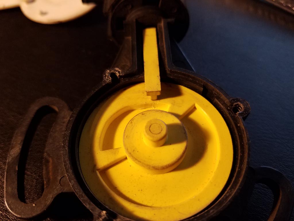
Photo 3. Guide Slot w/ Hole for Spring, Cam Stop and Lubrication Points:
At the top we see an angled guide slot and the hole to anchor the cam spring. The green marks indicate the surfaces that the cam rides on or rubs against which need to be lubricated all the way around: They are, from top to bottom, the vertical cylindrical surface that the outside edge of the cam will rub against, the flat circular surface that the bottom cam edge rides on as it turns and around the large hole where the bottom of the cam goes through the frame. The circular surface at the level of the spring hole does not need to be lubricated because nothing is moving against that surface.
The cam stop is marked and labelled. After the spring and cam are re-installed, the cam will be turned to the right 90 degrees to wind the spring, the cam latch with a ramp shape shown in photo 2. will slide up over the stop and then snap down into place holding the cam under spring tension in it's proper position. Remembering the approximate location of this stop will be helpful during the last step and it's shown in other photos.
Look at the right side edge of the hole at the bottom and you can see a lip which has been completely worn off on the left side. From this viewpoint the cam spring pulls the cam to the left, increasing the friction and wear on the left half.
Personally, I would lubricate THESE surfaces on the frame to lubricate the assembly and not the other way around by lubricating the cam first and then inserting it. Less messy and easier to handle for our next steps.
When the time comes, I'll be using �silicone grease� or �high temperature silicone grease� ← I have to look at the temperature specs again to see if that is more appropriate given the heat in the engine compartment. The VRV will be approximately vertical through it's adjustment range (typically set near the 11 o'clock position) so gravity will have an affect and any grease that gets soft will tend to eventually drift downward to keep lubricating the surface.
Normally I don't like to use an excessive amount of grease on parts, the excess usually just makes a mess. In this case I think a liberal amount is justified: for example, a finger application applying grease from a point half way up the side and across the surface that the the cam rides on. When the cam is pushed in some excess grease will probably come out the top and can be wiped off with a rag. For the bottom, I'll put some extra grease on the upper side half � around the hole. It doesn't need to be much, probably 1/16 in.(or 1.6 mm). With gravity and heat it may eventually drift into the gap to keep it lubricated for a long time.
Photo 4. Reassembly:
Align the hole in the cam in a straight line with the other end of the spring.
1.) After the surfaces have been lubricated, insert the cam spring first, using the guide slot to guide the end of the spring into the hole.
2.) Position the frame on your workspace or in your left hand (R hand if you are left handed) as shown in the photo. Position the cam leaning at an angle in the position shown here with the spring hole in the cam pointed directly toward the other end of the spring which will be inserted in the hole by following the next two steps (3. & 4.)
3.) Bring the leading edge of the cam up and over the the edge of the frame, straight toward the end of the spring and down into the frame at an opposite angle as shown in the next photo.
Photo 5. Place the Cam into the assembly at an angle as shown:
Move the cam over the left side of the frame and into this position.
The Cam was leaning up against the left side adjacent to the attachment point of the spring-to-frame which you can still see in this photo. The hole was lined up to meet the end of the spring for this step. Bring the cam up and over the side and DOWN on the opposite edge at the angle shown. The hole should be very close to the end of the spring. Now, HOLD the cam down in this position and turn the whole assembly over.
Photo 6. Fit the spring into the hole in the cam as described below the photo:
4.) The spring is almost in the hole! A near miss! (You might get it the first time!) That is why the alignment in the previous photo was important. Now, manipulate the cam very slightly to align the hole until the spring slips into it. As an alternative you can use a small screwdriver blade to push the spring toward the hole until it slips into place. When you get the spring in place wiggle the cam a little bit until the cam is seated and the cam shaft comes through the large hole on the back . You can also do this after the VRV is turned over for the next step.
From the back side check to make sure that the end of the spring can be seen in the small spring release hole on the frame. If not visible, the spring has detached and you'll need to go back to 'Photo 4.' and start over again from there.
Photo 7. Spring fully attached at both ends and Cam is in place:
Now we have to turn the cam to the right about 90 degrees to wind the spring and set the position of the cam ramp to the top. The Blue Line I drew on the right side of the cam represents the location of the cam latch on the back side of the cam.
The Red Mark indicates the position of the 'Stop' on the frame under the cam. As the cam turns Right, toward 90 degrees, the cam latch (which is shaped like a ramp) will ride up onto the 'stop,' lifting the cam slightly at the bottom of the photo until the end of the ramp is reached and the cam snaps back down behind the stop and is latched in that position.
You'll be pushing the cam downward as you turn it but remember that the cam will lift up at the bottom edge and you don't want too much pressure on that point or it will be hard to turn when it gets close to latching. The pressure should be applied in the middle of the cam and not toward the bottom edge.
Photo 8. Turn Cam to the Right, Frame to the Left:
Cam held between thumb on top, index finger on bottom. My thumb is too far down in this photo. Thumb placed at the center of the cam is best. You'll be applying downward pressure on the cam as it turns but only enough pressure to keep the cam seated as it is turned.
Now, using your right hand at the top of the VRV frame, (opposite hand if you are left handed) turn the Frame to the Left and the Cam to the Right. By the time the cam has moved about 75-80 degrees the bottom edge of the cam will rise up out of the seat. Turning a little bit further it will snap back down into place and latch!
Yippee! We are finished with that and can proceed to lubricate and assemble the rest of the VRV!
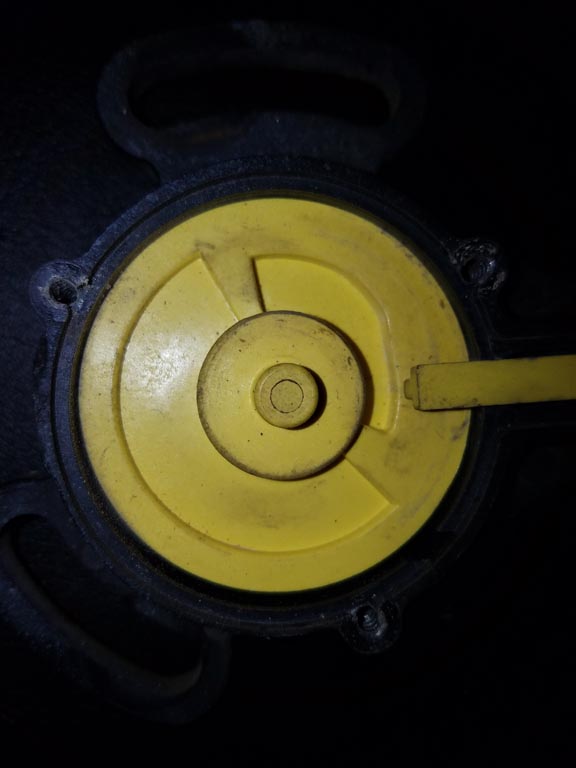
Photo 9. Lubrication surfaces:
Notice the Gap on the Right. The wear is on the Left half opposite the gap - caused by constant spring tension pulling the cam to the left.
These surfaces are small so some kind of applicator should be used = whatever works.
Shown as light blue paint: Lubricate these surfaces:
1) The flat surface of the cam wheel that the plastic link will rub against, just a light coat because the plastic link will be scraping excess to the sides.
2) The channel where the link bar slides up and down. The link bar actually does not contact that large surface area there is only very tiny contact along the sides of the link bar. The added grease I am showing in the bottom of that channel is only applied because gravity and heat will eventually allow that lubricant to flow downward into the gap between the cam wheel and the frame.
3) The red arrows point to the surface of the cam ramp where the post on the plastic link slides on the cam. The plastic link will be under spring tension pulling it upward so there is more friction and wear here.
Photo 10. Wear Surfaces on Cover Plate:
4) You can see the wear marks on the cover plate. I flipped the plastic link arm over and highlighted the marks where it rubbed against the cover plate.
I did not highlight the wear marks on the middle part of the cam but those surfaces match the marks on the cover plate. Lubricate those surfaces all the way around the circle.
These surfaces need to be lubricated before the Cover Plate is put back on which is the last step in the complete reassembly of the VRV, after the valve assembly at the top is installed. Good idea to lubricate them now so as not to forget later.
That's it. Now you are ready to complete the re-assembly and install the VRV in the Vehicle.
If you are using the top part of a GM VRV, the next post will show exactly how and where to place it for a prefect adjustment.
Last edited by Fixnstuff; 05-19-2017 at 11:00 PM.
Reason: Add a bold text title line. Add Photo #10 with Explanation.
Added Photo #10 with explanation to the Previous Instructions posting.
I added a photo labelled "Photo 10. Wear Surfaces on Cover Plate:" (with explanations) at the end of the previous post, 'HOW TO REMOVE, LUBRICATE AND REINSTALL VRV CAM.'
I've had this one apart for so long I had forgotten about the cover plate, so now that post is complete.
OK, a successful report of using an 87 VRV on my 86 Ford pickup. I got the used VRV on eBay, and it appears that E5TZ-7B200-A and FOTZ-7B200-A are sufficiently interchangeable to work fine! (The cam shape looked slightly different from the old one he pulled out, but the new one works fine.)
I took the VRV to my mechanic and had him install it, glad I did. He installed it, and said it seemed to be working fine, but a vacuum actuator also needed to be replaced for the shifting to work properly. For $38 + plus installation, it seemed cheap at the price. (and I don't really know how the system works) When he brought it back after a test drive, it was working perfectly, and it is a pleasure to drive! So success!! Thanks Fixnstuff for the detailed writeup of the rebuild process, I'll apply it to the old VRV to rebuild it using the GM parts. The peg on the old VRV actuator rod was worn about 1/2 way, resulting in rough shifting and intermittent behavior (perhaps also due to the defective vacuum actuator as well). So, thanks to everyone on this list for educating me on this process!! I'll report back on my rebuild, but I won't try it out for a long time...!
I just wanted to chime in on this VRV post. Over the last few weeks, I was reading up on the VRV from threads like this and on other IDI forums, and I got inspired to use my 3D modeling, engineering, and prototyping experience to see if I couldn't make some headway in building an inventory of VRV parts. I'm far enough along now that I felt confident enough to post my progress: New ?IDI-Online? C6 VRV (Vacuum Regulator Valve) Progress. For Sale Possibly In August. ? IDI Online
Using my spare VRV, I completely disassembled the device and meticulously measured all the aspects of the housing, cover, cam, cam-link, valve, valve housing, and castle nut. I was able to capture the entirety of the VRV down to approximately 5 thousandths of an inch, and model it in CATIA. Then I was able to simulate its usage virtually in CATIA's Assembly Design workbench, verifying my measurements were accurate. Using the Clash Detection software, I verified that it fit together perfectly, just as if it was brand new.
I've already sent this prototype off for three different types of plastics and will expect them for materials testing in the next few weeks. Also, I'm working with another flexible plastic/resin supplier to develop a new diaphragm design. Ultimately, I'm pretty confident I'll be able to provide two things: An inventory of VRV replacement parts (as well as finished product VRV's), but also, I'd like to custom design an inventory of end-product VRV's that use less moving parts than the stock VRV. All this depends on the quality of the plastics I've been able to test, and the earlier examinations with cheaper plastics didn't suffice. I'm exploring a lot of options, and my version may look nothing like the stock VRV. I'm throwing out the conventional IDI playbook.
I'll continue to post my detailed progress on my VRV Progress article, if you want to get tangled in those weeds. But I'll post the major advancements on this thread, since it's basically the best thread discussing the IDI VRV on the net.
I just wanted to chime in on this VRV post. Over the last few weeks, I was reading up on the VRV from threads like this and on other IDI forums, and I got inspired to use my 3D modeling, engineering, and prototyping experience to see if I couldn't make some headway in building an inventory of VRV parts.
SUPER! I'm in a rush right now to pick up some new parts and get some work finished on my truck so I can drive it. I'll post again late tonight with more details and send a PM to you so I can arrange to send some things directly to you. I'm glad you've jumped in with your skills and other abilities and I appreciate your plan genscripter. I wish I would have known before you sent your work off to be prototyped, I could have given you some very useful information including the original EATON Corporation Patents. (There are two).
Since my last post, here is part of my progress: I was very lucky to find and buy a replacement VRV that is like brand new and seems to have zero wear! I was planning to dimension the parts in mechanical drawings with patterns to use for fabrication and make those available for download to anyone who wanted to make (machine) their own replacement parts. I also have a brand new GM VRV. As a former draftsman before the days of CAD, I was going to do that on a drafting board because, although I have CAD software for Linux, I don't have time for the learning curve. In fact I don't even have the space anywhere in my 2 bedroom duplex to set up a drafting table!
Secondly, I had been shopping pawn shops for a certified digital caliper, and after some months I finally found one with international certifications and a USB port. I had been hoping for a Mitutoyo but every one I found was either too old, corroded, out of calibration or otherwise not testable. I found one, 8 inch with USB port and international certifications that tested perfectly every time. It always returned to zero when I closed it, and none of the Mitotoyos that I tested did that. It was a name brand I had not heard of before, "INSIZE" so I researched the company and was surprised to find that it is an excellent manufacturer of high precision and scientific measuring instruments. US Division: INSIZE CO., LTD. I bought that one in and ordered a depth gauge base for it plus a new set screw (Which I had lost). I need to go buy a new battery for it.
The significance of the digital caliper is that I can dimension my "like brand new" VRV and send those dimensions to you to compare and correct any of your dimensions. One mistake I noticed in your drawings is how you measured the cam ramp. You measured between two wearing surfaces. The outside of the cam wheel on the cam side is a wearing surface, as is of course, the cam ramp surface. You should have taken the offset inside dimensions from the center circle which has zero wear, to equally spaced (in degrees) points on the cam ramp which would have given more accurate dimensions for the curve. You COULD measure across the diameter of two opposite non-wearing sides of the cam wheel as a reference and add any difference in wear to your dimensions for the cam ramp. Actually you would have to take outside dimensions of the cam wheel at every location where you previously measured the cam ramp to make adjustments to each of those compared compared to the good reference measurement. ALSO, did you examine the face of the cam ramp under magnification? Since the "cam follower," the (usually) yellow piece connected to the spring at the top and which rides on the cam face at the bottom end, does not reach the bottom of that recess, so as you can see in photos I posted previously, there is a tiny ridge at the bottom of the cam ramp that does not get any wear. By taking an inside measurement, as I suggested, and keeping the point of your moving caliper jaw flush and in contact with the bottom of the recess you may be able to catch that ridge for a perfect original dimensions.
How did you determine where along the face of the cam/or outside diameter of the wheel to take those dimensions? At the ends of the cam recess the lines appear to go to the center of the cam wheel (center of the post on top of the cam wheel) It looks like 120 degrees. That is divisible by 6ea. 20-degree divisions and including the ends, 8 different locations to measure OR 16 if we use 10 degree increments. I am going to use a clear plastic protractor with full lines every 10 degrees to layout those points to measure from, modify the protractor for the job.
The offset dimensioning, to measure a curve or compound curve, or design the same type of curve, is something I learned while studying yacht design extensively. There is also a graph in the patents (which I haven't looked at in a long time) which shows the regulated vacuum at various degrees of the throttle position. This VRV is more complicated in it's function than meets the eyes and was developed by EATON corporation engineers with the engineering specifications for C-6 transmissions and probably tested with expensive lab equipment. Their patents are not on the specific parts, they are on the whole method of controlling vacuum shift points of a transmission from a diesel injection pump. the second patent is called an improvement but essentially that improvement is adding an electronic throttle position sensor for GM diesels. By the way I found no indications that EATON's patents have expired or were discontinued for any reason and normally I would find that information in the patent search sources I used. The Eaton Corporations are EXPERTS in drive-line systems including controlling the most advanced transmissions in the world. Their sales in 2016 was, I think 19 billion USD so you can understand why FORD was not successful in negotiating a new contract to make more VRV's. I THINK it is somewhat possible that EATON has benn able to maintain certain aspects of these original patents though superseding patents. I really don't know at this point. They are either expired or AC Delco has a licensing agreement to make aftermarket VRVs for GM diesels.
Back to the "offset dimensioning' for the cam curve- I was planning to get a degree in Yacht Design, actually a Mechanical Engineering degree with a minor in Yacht Design but my work as a commercial construction extimator took me in the direction of Architectural design.
Anyway, I KNOW ENOUGH TO BE HELPFUL to you. I have researched this extensively, including plastics formulations. Color coding is a good start to identifying which plastics were used by matching up their properties but there are several high tech methods of analysing plastic compositions for reverse engineering. A lot of plastics manufacturers have at least one of several methods to do that.
I also researched various ways to fabricate these parts as "Do It Yourself" projects. With accurate patterns to use, that is very doable for the two main wearing parts, the cam and the came follower. I've also given very much thought into refurbishing the existing parts to bring them back to original specifications and that is also very do-able at home with the proper patterns. I may go ahead and finish that up for us POOR people with very little money who need to fix their VRV's but probably not until winter is here.
The valve assembly is the most complicated part. The most precision is where the center of the brass piece through the diaphragm seats, = those very tiny vent notches that a meter the level of vacuum after the diaphragm is closed. (I didn't see those in your drawings, btw.) Then there is the flat metal spring. I've gone so far as to search for Chinese manufacturers who make parts like this. When you have accurate specifications it's not difficult to find companies willing to make the parts. As I've mentioned in earlier posts, I'm pretty sure that the diaphragm is silicone rubber and it's the least likely part to fail. In the old VRV that I have, made in 1985-86 it is still very flexible and seems to seat well. along the outside edge where it seats, there is not going to be any detectable wear on the black plastic. The wear will be at that center hole with the three vent slots where the brass part at the center of the diaphragm seats. AND the tension of that flat steel spring, being compressed most of it's life, it's likely to be a bit weak.
I may have mentioned before that these parts are pressure moulded thermoplastics - at very high pressures, probably 25 tons. The most expensive part in the manufacturing process is machining the moulds! Moulds are less expensive (materials-wise) for short production runs, which this project would be. LOTS of companies can produce the parts, hundreds of companies, many of them looking for jobs to do and offering very low costs per piece but the limited production will raise the costs and the complexity and expense of the moulds will add a lot to the over all costs of a short production run.
One of my big handicaps is NO EXTRA MONEY to spend. My rent went up another added $100.00 for most of the past year and my total income is less than $800/month. I get some assistance in rent but after all of my bills there is very very little left. Most of that goes to repairs on my truck and sometimes I have to save for a couple of months to afford that. For that reason I didn't consult with anyone in these various professions. I had planned first to contact EATON and ask about the status of their two patents and if AC Delco was manufacturing he GM VRVs under a licensing agreement. I would of course mention our problem with the Ford/IH/Navistar C-6 VRVs and the necessity for at least some replacement pars for those that wear out.
SO, due to my miserable economic situation, the focus of my research pretty much turned from seeing to it that someone would manufacture new replacement parts to much less expensive ways to either make DIY replacement parts or recondition existing parts with instructions and accurate patterns. I hope to do that his winter but I will share everything that I have with you for your project and hope that it succeeds.
Manufacturing an entirely new VRV is a very TALL order, and MORE-SO finding a better way to do it than the EATON Corporation did. With enough brainstorming it could be done, there is always a better way. Reverse engineering: The frame is probably of least concern to replace. The wearing surfaces that matter are where the cam wheel rubs against it and a little bit of excess play there is probably of very little concern with respect to over-all function of the VRV. It's also probably the most expensive part to machine into an injection mould. I would be tempted to skip that one if necessary. I've also researched ways to build up the worn surfaces such as those on the frame. (I have other ideas for the cam wheel) and although I'm sure that there are some process that would work, I haven't identified one YET. Over the past 3 years I've dived into this for a couple of weeks at a time every few months.(at first it was months straight). Although I haven't posted to this thread in a full year, I've still been doing that. The old VRV you see in the photos I posted is STILL apart in a jar here on my desk. I have the new ones (FORD near new and GM NEW) in my "hard to find spare parts" case in my bedroom. With good weather finally here now is a bad time for me to dive in again. But I'll do my best.
MY NEXT STEP in this whole VRV matter was going to be: START A NEW CLEAN TOPIC (linked to this thread or parts of it as needed) and keep it clean and focused on solving the problem, to proceed from anew with all of the key elements right at the beginning including the patents, because this topic thread is tooo long. I think most people will not be inclined to go though all of these posts to find a solution.
You can start a new one if you want, genscripter! Use a title that clearly expresses where we are going with this issue. That way, people can come right to SQUARE ONE!
Sorry this is so long (again). I have to run now to pick up parts at the dealership and finish working on my truck so I can DRIVE IT. It has become my daily driver now.
I'll check back in here later. I'll send a PM to you later tonight genscripter (after dark) to establish direct contact for exchanging information. I'm willing to help in any way, except giving you my new VRVs.
I'll check back here tonight.
OH NO! One more comment for now:
Using my spare VRV, I completely disassembled the device and meticulously measured all the aspects of the housing, cover, cam, cam-link, valve, valve housing, and castle nut. I was able to capture the entirety of the VRV down to approximately 5 thousandths of an inch,...>snip
I like ZERO tolerance for precision work and for that cam ramp I was looking at a 0.001 in. tolerance limit. That curve is critical in my opinion. 5 thousandths is too much in my opinion. To get that kind of accuracy on a used VRV takes quite a bit of close examination (magnification) and multiple dimensions to cross check everything but with a NEW one it's not a problem. Mine is as close to brand new as anything I will ever see so lets compare dimensions! Like yours, my caliper is certified to 0.0005 (5 ten-thousands = 1/2 of one-thousandth) and returns to zero every time so it should be accurate. Just need to get a battery and a protractor. TTYL, you can send a PM to me first with your contact info if you want. I'll be outside working until about 9:30 PM unless i decide to run an extension cord and lights out to my truck parked on the street.
I don't want to make a new thread. I've read all the major VRV threads on FTE, OB, and DS, and this one is by far the most interesting. Making a new thread just spreads all the pertinent information across the forum. Let's just keep posting here. I like the fact that it's long and descriptive. That's kind of the benefit of online forums.
I don't want to make a new thread. I've read all the major VRV threads on FTE, OB, and DS, and this one is by far the most interesting. Making a new thread just spreads all the pertinent information across the forum. Let's just keep posting here. I like the fact that it's long and descriptive. That's kind of the benefit of online forums.
OK. People will likely start at the end of the thread anyway. I got quite sick from excessive heat and very high humidity in my place yesterday so I couldn't get back to this last night. Almost zero insulation in the attic (about 1 inch of old compressed rock wool from 1941). with a dark roof this place heats up like an oven! It got to 92 deg. F outside but in here it was surely well over 100 degrees F and very high humidity. Feeling much better this morning and before noon I'll lift an old air conditioner into my bedroom window and get that sealed in. I got too sick and weak to do it yesterday.
See the photo in post #65. That is enhanced from the photo Trucknewowner posted of the cam in the VRV he bought from cadunkle. That VRV is in excellent condition and I'm pretty sure that the ones with the white side covers like that one are from the last run of replacement parts by the manufacturer, so it's a late replacement VRV. Notice the wear into the cam face leaving that tiny ridge at the bottom. The ramp surface of that ridge represents the original "as new" curve of the cam at that hump in the curve which wears down the fastest. Try to make sure that at least one of your dimensions and the point on the sliding jaw of your caliper catches that ridge for an accurate measurement of the curve in the cam. My 8 in. caliper "inside" jaws will barely fit into that recess and to do an inside measurement (which I prefer) in order to avoid the wear zone on the outer edge of the cam wheel - then that measurement, the dimension from the outer edge of the cam wheel to the curve can be simply calculated arithmetically. Then we'll have two different and accurate location dimensions for the curve to go by, from the inner circle and then arithmetically to the known unworn diameter of the outer circle of the cam wheel.
I or you will need to do this fine dimensioning under magnification. l have a Magnifier Head Strap With Lights that I bought at Harbor Freight and it works very well for detail work like this. Magnifier Head Strap With Lights
I just tried it using my desk lamp for lighting but I have no battery for my caliper yet.
I'll be sending a PM to you in a few minutes.
I was just reviewing the EATON Corporation patents and I've decided to upload both patents today, the first for the Ford/IH/Navistar IDIs with C-6 transmissions and the second one for GM diesels which I believe applies to the turbo 400 transmissions. (Possibly also applies to the Turbo 350 transmission). There is useful information in both of those patents for anyone who wants to study and understand these VRV's and how they work.
Now I need to send a PM to genscripter, put the air conditioner in my bedroom window and then go outside and finish hooking up transmission lines to my radiator (I removed the radiator it to get a good solder repair around a leaking joint where the upper hose inlet tube goes into the top tank. I put it on a bench and got an excellent solder repair this time DOING IT RIGHT with the correct acid core solder, I chose 40/60 Sn/Pb 40%Tin / 60% Lead and acid flux ) For a good repair don't use rosin core solders or flux and use a minimum of 60% Lead in a 40/60 Tin/Lead solder. In the USA the Tin percentage is listed first followed by the Lead percentage. That may be reversed in other Countries. I'll be doing a post later on this repair in the 'What Did You Do to Your Truck Today' thread explaining what to use, why, and how to do it. I also have to mount the auxiliary transmission cooler and put the grille assembly back on and refill the cooling system with Lifetime anti-freeze, I chose PEAK FINAL CHARGE GLOBAL. I NEVER want to do a coolant flush again! I HATE that job!
 05-13-2017, 07:32 AM